1
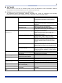
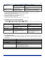
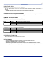
2 SOFTWARE Software tools for use with the DTSXM System include the DTSX200 Control Visualization Software (DTAP200) and the DTSX200 Data Conversion Software (DTAP200D). DTSX200 Control Visualization Software (DTAP200) The DTSX200 Control Visualization Software (DTAP200) tool is used for configuring and controlling temperature measurement by DTSX200, as well as displaying measurement data graphs. Item Boot modes Control mode Monitoring mode Trace mode Calibration mode Measurement configuration functions (*1) (Global) measurement settings (Channel) measurement settings (Channel) fiber settings Alarm settings Zone temperature data generation settings DTSX200 control functions Status display functions Alarm display Measurement result display functions Help functions Calibration functions (*5) Communications functions (*3) Connect/Disconnect (*3) Start/Stop measurement (*4) Self-test (*4) Connection status display and measurement status display Notification Detailed information display Graph settings Graph display Version information display and user manual display Calibration of various sensor fiber parameters Communications with DTSX200 All Rights Reserved. Copyright © 2014, Yokogawa Electric Corporation Description The control mode is used for configuring and controlling measurement, as well as displaying measurement results while connected to the DTSX200. The monitoring mode is used for displaying measurement results while connected to the DTSX200. The trace mode is used for displaying trace data without connecting to the DTSX200. The calibration mode is used for tuning temperature measurement parameters while connected to the DTSX200. Settings for channel combination, measurement sequence, measurement mode (single-ended or double-ended), measurement interval and measurement start time Repetition rate, measurement time (*2) or averaging times, distance range, sampling resolution and fiber failure detection threshold Fiber length, wavenumber, group index, loss correction, temperature offset correction and winding coefficient (distance-depth conversion factor) Up to 10 alarm detection zones can be defined with temperature high limit, low limit, rise limit, fall limit and difference limit values specified for each zone. Up to 100 data generation zones can be defined with the temperature output data type (average, maximum, minimum, difference or slope) selected for each zone Authentication using username and password Self-diagnosis by DTSX200 An alarm is indicated by a lit alarm lamp button. Alarm type and alarm location (only for the first occurrence) Data type (temperature, signal level), data unit, graph type (2D or 3D) and display range Displays measurement data. Fiber connection calibration and fiber parameter calibration Uses SSH, SFTP and SCP. GS 39J02B45-01E Jan. 10 2014-00