1
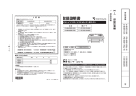
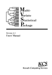
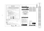
Terra Harvest, EUGS, and Cursor on Target in the
Improved Sensor Integration (ISI) System
by Jesse B. Kovach and Timothy C. Gregory
ARL-TR-6638
Approved for public release; distribution unlimited.
September 2013
NOTICES
Disclaimers
The findings in this report are not to be construed as an official Department of the Army position
unless so designated by other authorized documents.
Citation of manufacturer’s or trade names does not constitute an official endorsement or
approval of the use thereof.
Destroy this report when it is no longer needed. Do not return it to the originator.
Army Research Laboratory
Adelphi, MD 20783-1197
ARL-TR-6638
September 2013
Terra Harvest, EUGS, and Cursor on Target in the
Improved Sensor Integration (ISI) System
Jesse B. Kovach and Timothy C. Gregory
Computational and Information Sciences Directorate, ARL
Approved for public release; distribution unlimited.
Form Approved
OMB No. 0704-0188
REPORT DOCUMENTATION PAGE
Public reporting burden for this collection of information is estimated to average 1 hour per response, including the time for reviewing instructions, searching existing data sources, gathering and maintaining the
data needed, and completing and reviewing the collection information. Send comments regarding this burden estimate or any other aspect of this collection of information, including suggestions for reducing the
burden, to Department of Defense, Washington Headquarters Services, Directorate for Information Operations and Reports (0704-0188), 1215 Jefferson Davis Highway, Suite 1204, Arlington, VA 22202-4302.
Respondents should be aware that notwithstanding any other provision of law, no person shall be subject to any penalty for failing to comply with a collection of information if it does not display a currently
valid OMB control number.
PLEASE DO NOT RETURN YOUR FORM TO THE ABOVE ADDRESS.
1. REPORT DATE (DD-MM-YYYY)
2. REPORT TYPE
3. DATES COVERED (From - To)
September 2013
Final
May to September 2013
4. TITLE AND SUBTITLE
5a. CONTRACT NUMBER
Terra Harvest, EUGS, and Cursor on Target in the Improved Sensor Integration
(ISI) System
5b. GRANT NUMBER
5c. PROGRAM ELEMENT NUMBER
6. AUTHOR(S)
5d. PROJECT NUMBER
Jesse B. Kovach and Timothy C. Gregory
R.0008471.2
5e. TASK NUMBER
5f. WORK UNIT NUMBER
7. PERFORMING ORGANIZATION NAME(S) AND ADDRESS(ES)
8. PERFORMING ORGANIZATION
REPORT NUMBER
U.S. Army Research Laboratory
ATTN: RDRL-CII-B
2800 Powder Mill Road
Adelphi, MD 20783-1197
ARL-TR-6638
9. SPONSORING/MONITORING AGENCY NAME(S) AND ADDRESS(ES)
10. SPONSOR/MONITOR'S ACRONYM(S)
11. SPONSOR/MONITOR'S REPORT
NUMBER(S)
12. DISTRIBUTION/AVAILABILITY STATEMENT
Approved for public release; distribution unlimited.
13. SUPPLEMENTARY NOTES
14. ABSTRACT
The Improved Sensor Integration (ISI) project is an effort to cross-cue various force protection and persistent surveillance
systems from unattended ground sensor systems and other data sources. The ISI systems communicate primarily through
cursor on target messages. The Terra Harvest controller architecture was adopted to integrate the Applied Research Associates
Expendable Unattended Ground Sensor (EUGS) system into the ISI project and provides a potential entry point for other types
of unattended sensors. This report describes the architecture used to integrate EUGS into the ISI system by way of Terra
Harvest and Cursor on Target, and discusses some of the issues and solutions that were identified during the integration.
15. SUBJECT TERMS
Cursor on Target, CoT, UGS, EUGS, Terra Harvest
17. LIMITATION
OF
ABSTRACT
16. SECURITY CLASSIFICATION OF:
a. REPORT
Unclassified
b. ABSTRACT
Unclassified
c. THIS PAGE
Unclassified
UU
18. NUMBER
OF
PAGES
24
19a. NAME OF RESPONSIBLE PERSON
Jesse B. Kovach
19b. TELEPHONE NUMBER (Include area code)
(301) 394-3988
Standard Form 298 (Rev. 8/98)
Prescribed by ANSI Std. Z39.18
ii
Contents
List of Figures
iv
List of Tables
iv
1.
Introduction
1
2.
System Architectural Overview
2
3.
Terra Harvest Controller Architecture Summary
4
4.
EUGS Terra Harvest Integration
5
5.
4.1
EUGS Receiver and Supporting Software ......................................................................6
4.2
EUGS Terra Harvest Plugin ............................................................................................6
EUGS Location Editor Tool
7
5.1
Location Editor ................................................................................................................8
5.2
ARLCoordinates.NET Library ........................................................................................8
5.3
Display Conventions .....................................................................................................10
6.
Terra Harvest Cursor on Target Converter
10
7.
Cursor on Target Integration Issues
11
7.1
Type Codes ....................................................................................................................12
7.2
Time Handling ...............................................................................................................13
7.3
Height Above Ellipsoid vs. Mean Sea Level ................................................................13
8.
Conclusions and Next Steps
14
9.
References
15
List of Symbols, Abbreviations, and Acronyms
17
Distribution List
18
iii
List of Figures
Figure 1. EUGS ISI architectural overview. ....................................................................................4
Figure 2. EUGS Location Editor tool. .............................................................................................8
Figure 3. Example EUGS location file. ...........................................................................................8
List of Tables
Table 1. CoT type mappings. .........................................................................................................12
iv
1. Introduction
The Improved Sensor Integration (ISI) project is an effort to cross-cue various force protection
and persistent surveillance systems (mostly imagers) from unattended ground sensors (UGSs),
including the Expendable Unattended Ground Sensor (EUGS) system from Applied Research
Associates (ARA) (1) as well as other data sources. In order to accomplish this, the source
sensors must be able to pass target location messages to the destination persistent surveillance
systems and the destination systems must be able to parse, interpret, and act upon these
messages. Generally, these systems use custom message formats, making interoperability
difficult.*
The traditional approach to integrating different sensor systems is to modify each destination
system to add support for processing the particular message formats generated by a source
system. This “stovepipe” method is often expedient for small integration projects, but does not
scale well as the number of systems (and associated translators) increases. As a result, several
common architectures and message formats for sensor and situational awareness data exchange
have recently emerged. Cursor on Target (CoT) and Terra Harvest are two of these architectures,
and a combination of the two was chosen to facilitate integration for the ISI project.
CoT (2) is an extensible markup language (XML) message format and associated (minimalist)
communications architecture originally designed by the MITRE Corporation for the Air Force.
CoT was designed to be lightweight and easy to implement, and is supported in some fashion by
over 100 military systems. CoT messages are exchanged over standard TCP and UDP
connections using a straightforward one-message-per-connection protocol often called “OpenSquirt-Close.” Most of the persistent surveillance systems in ISI were already capable of cuing
from CoT messages, so CoT was chosen as the message format for integrating persistent
surveillance systems into the overall ISI architecture.
Terra Harvest (5) is an emerging UGS system architecture developed by the U.S. Army Research
Laboratory (ARL), Defense Intelligence Agency (DIA), and the University of Dayton Research
Institute (UDRI). Terra Harvest consists of a Java and Open Services Fateway Initiative (OSGi)based application programming interface (API) for UGS controllers, a standardized common
lexicon for UGS observations and commands, and a set of associated wire protocols for sending
and receiving these standardized observations and commands (5). Integration with Terra Harvest
can be accomplished at the API, wire protocol, or lexicon level. ARL and ARA had previously
developed Terra Harvest components for generating CoT messages and interfacing with the
* In the case of UGSs, the use of these custom protocols is often justified due to extreme constraints on power, bandwidth,
and other resources.
1
EUGS system, so Terra Harvest was chosen as the architecture for integrating EUGS (and future
UGS systems) into ISI.
Although most of the components and interfaces necessary for the EUGS ISI integration already
existed in some form prior to the start of the project, a number of issues were nevertheless
encountered during the integration effort, mainly due to differing interpretations of the CoT and
Terra Harvest standards. This report provides an architectural overview of the EUGS ISI
integration and describes the problems and associated solutions identified during the integration
effort.
2. System Architectural Overview
The EUGS ISI integration architecture consists of the following software and hardware
components:
•
One or more EUGS sensors, which detect seismic events and transmit event reports and
status messages over a radio link. The EUGS sensors are commercial off-the-shelf (COTS)
products from ARA.
•
An EUGS receiver, which receives transmissions from the EUGS sensors and outputs a
line-level audio signal, which connects to a PC sound card. This is a COTS product
supplied with the EUGS system.
•
The ReceiverCore software runs on a PC and decodes the audio signal from the receiver.
This is a COTS product supplied with the EUGS system.
•
The THOSE Terra Harvest controller software, which is a reference implementation of
the Terra Harvest controller architecture developed by ARL, UDRI, and DIA. THOSE
provides (among other things) an observation store and event handling framework used by
the ISI Terra Harvest plugins to store and exchange configuration information and sensor
data in a standardized format.
•
The Terra Harvest EUGS plugin, which runs within the Terra Harvest controller to
process messages from the ReceiverCore application and post them to the Terra Harvest
observation store. This was originally developed by ARA and updated by ARL.
•
The Terra Harvest CoT Converter Plugin, which runs within the Terra Harvest
controller to retrieve observations from the observation store and convert them to CoT
messages. This was preexisting software developed by ARL.
2
•
The EUGS Location Editor software, a standalone application for editing the sensor
location list used by the EUGS plugin. This was developed by ARL for this project.
•
A CoT message router, a software application which receives CoT messages from the
Terra Harvest CoT Converter as well as other sources and routes them to destinations in a
flexible manner. ISI uses a custom CoT router developed by MITRE for this project, details
of which are beyond the scope of this report.
•
Various external display and persistent surveillance systems, which receive CoT
messages from the message router and act on them, including the TerraSight mapping and
video processing system from SRI/Sarnoff† (10). Details of these systems are outside the
scope of this report.
All of the EUGS integration software components run on a single Windows 7 PC. The
interactions and data flow between these components is shown in figure 1.
† Despite the similar naming, TerraSight is an independently developed product not related to Terra Harvest.
3
850 MHz Radio Link
EUGS
Sensor
EUGS
Receiver
Network
Audio Cable
External
Systems
CoT over
TCP/UDP
USB
sound
card
CoT
Receiver
Core
CoT Router
EUGS Messages
External
Sensors
CoT over TCP
EUGS
Plugin
Observation
Store
CoT
Converter
TH Observations
THOSE Controller
Windows 7 PC
Figure 1. EUGS ISI architectural overview.
3. Terra Harvest Controller Architecture Summary
Terra Harvest is an open architecture for UGS controllers. Terra Harvest defines hardware and
software interfaces to support tasks common to all sensors.
An UGS controller functions as a gateway between a sensor and higher level systems. The
controller manages sensor configuration, receives and distributes sensor detections, executes
sensor commands, and provides communications with other systems. An UGS controller does
not provide a display of sensor events or a long-term data store, leaving these tasks to higher
level systems.
Terra Harvest software is implemented in Java and based on the OSGi framework, which is an
open source module system for Java. The OSGi framework allows functionality to be added,
4
removed, and updated at runtime without restarting the system. Support for sensors and other
desired functionality is added to the system as plugins in the form of Java Bundles. OSGi defines
an API for configuration and control of installed bundles. Terra Harvest builds on OSGi to define
APIs for UGS-related tasks and provides a Web-based graphical user interface (GUI) to
configure the plugins on a controller.
To meet its goal of supporting all sensors, Terra Harvest defines Java interfaces for tasks
required by sensors. A list of the supported functions is shown below:
•
Defining, configuring, and controlling assets (sensors).
•
Custom communications.
•
Image capture.
•
Event logging.
•
Common lexicon for describing events from sensors.
•
Collection of events (observations) from sensors.
•
Persistence of events and generic data.
Support for an asset (sensor) would be implemented using an asset bundle. An asset bundle must
handle all the functions required by the asset such as parsing sensor data, generation of sensor
events, activation and deactivation of the asset, and capturing data. An asset bundle must
implement the necessary Terra Harvest interfaces to properly interact with the Terra Harvest
system.
Events or data from sensors are represented as Terra Harvest Observations. Observations are
represented in a common lexicon and stored in a database (the Terra Harvest ObservationStore)
that resides locally on the Terra Harvest controller. Data in the ObservationStore are available to
other components such as a data exfiltration component, which reformats and distributes them to
other systems. For the ISI project, the events are reformatted into CoT messages.
4. EUGS Terra Harvest Integration
The EUGS system (as with most UGS systems) is provided by ARA as a complete solution
consisting of sensors, a receiver, and a software application that displays sensor data on a map.
To integrate EUGS into the ISI system, the ARA EUGS application was replaced with a set of
Terra Harvest components that generate Terra Harvest common lexicon observations from
5
EUGS events. This section describes the Terra Harvest components used for the EUGS ISI
integration.
4.1
EUGS Receiver and Supporting Software
EUGS sensors send four basic message types: activity detections, tamper detections, periodic
status messages, and low battery warnings. Each message contains the sensor’s serial number for
identification. The sensors do not provide position information. The sensors transmit messages
using a custom binary protocol.
ARA produces two versions of the EUGS receiver. The Configuration A receiver demodulates
(but does not decode) the sensor transmissions and outputs a line-level audio signal. The receiver
is connected to an external computer equipped with an audio input device.‡ This computer runs
an ARA-provided Windows application, ReceiverCore, which decodes the audio signals and
outputs the decoded message as XML over a TCP socket connection. The Configuration B
receiver contains an embedded processor that decodes the EUGS messages and is equipped with
serial and Ethernet connections. The B receiver outputs decoded messages as XML over either
the serial port or a TCP socket. Both configurations ultimately use the same (ARA-defined)
XML message format. The ISI project required supporting the A receiver.
4.2
EUGS Terra Harvest Plugin
To support a previous demonstration, ARA developed a Terra Harvest plugin to interface with
the B receiver. This plugin receives the custom XML messages from the receiver, converts them
to Terra Harvest common lexicon observations, and posts the observations to the Terra Harvest
observation store. Because the A and B configurations use the same message format, this plugin
can be used unmodified with an A receiver if the ReceiverCore application is started manually.
To remove this manual step when using the A receiver, ARA developed a new version of the
plugin that checks if ReceiverCore was running and starts it, if necessary. The new plugin
contains a configuration option to enable or disable this feature so that it can be used with either
receiver configuration.
During initial testing, we discovered that ReceiverCore sometimes “hangs” and stops producing
data. As a workaround, ARA added an additional check to the plugin to kill and restart
ReceiverCore if no messages were received within a defined time interval.
EUGS sensors do not provide position information, so sensor locations must be manually
surveyed and entered by the user. The EUGS kit includes a Garmin GPSMap 60Cx handheld
global positioning system (GPS) receiver for surveying sensor locations. When emplacing
sensors, the user records (or calls in) the locations of the sensors for later entry into the sensor
processing system. The standard ARA EUGS display application provides a GUI for entering
‡ ARA recommends a Creative Labs Sound Blaster X-Fi Go! Pro.
6
this information, but this software is not used as part of Terra Harvest. The original version of
the EUGS plugin stored sensor locations as a single, concatenated, comma-delimited string in
OSGi configuration admin. This sufficed for demonstration purposes and allowed the sensor
locations to be set by OSGi-aware configuration tools such as the Terra Harvest GUI, but was
too cumbersome for operational use. For the ISI project, ARL modified the EUGS plugin to read
the location list from an external text file and developed a GUI tool (described in section 5) that
allows a user to easily edit the location list. Strictly speaking, this method is not Terra Harvest
compliant due to the reliance on an external configuration file that is not visible to standard Terra
Harvest configuration tools. Ideally, the location list editor functionality would be made
available within the Terra Harvest framework, but the short project schedule did not allow for
this development effort.
ARL made some additional modifications to the EUGS plugin in order to streamline setup of the
ISI system. The generic default configuration options for the plugin were changed to the values
needed for ISI, eliminating several manual steps from the configuration process. An option was
added to record signal-to-noise ratio data to an external log file for use when setting up the
receiver. Finally, an option was added to maintain a history of sensor tamper warnings and report
the tamper status as part of periodic sensor status observations in addition to individual tamper
detection observations. This option was added to provide more flexibility in early integration, but
was not used in the final configuration.
5. EUGS Location Editor Tool
The EUGS Terra Harvest plugin reads sensor location information (latitude, longitude, and
altitude) from a comma-delimited text file. For initial development and testing, this file was
edited by hand. However, for operational use, we developed a simple GUI to allow users to
easily edit the file and to enter sensor locations using three commonly used coordinate systems.
Figure 2 shows a screenshot of the EUGSLocationEditor tool, and figure 3 shows an example
location list file generated by the tool.
7
Figure 2. EUGS Location Editor tool.
12345,38.928760,-77.046400,53,false
31337,38.928480,-77.046650,57,false
49200,38.928470,-77.046080,55,false
Figure 3. Example EUGS location file.
5.1
Location Editor
The location editor was developed in Microsoft Visual Studio 2010 using .NET Framework 2.0
and uses a standard Windows Forms DataGridView control to edit the sensor list. The
application allows the user to view and enter sensor locations using decimal degrees, Military
Grid Reference System (MGRS), and Universal Transverse Mercator (UTM) coordinate formats.
Internally, all coordinates are stored as decimal degrees and converted to/from MGRS or UTM
as necessary for display and data entry. The DataGridView contains columns for latitude,
longitude, MGRS, and UTM, which are shown and hidden as appropriate when the user changes
between position display formats using the drop-down list. Buttons allow the user to delete the
currently selected sensor, save changes, or discard all changes since the last save.
5.2
ARLCoordinates.NET Library
Conversion between coordinate systems is handled using the ARLCoordinates.NET library. This
library has its origins in a 1994-vintage C library obtained from the Army Corps of Engineers
Topographic Engineering Center (TEC), now known as the Army Geospatial Center. For
previous projects, ARL ported the TEC code to C# and wrapped it in a set of C# classes. During
8
testing of the EUGSLocationEditor application, a number of issues were identified in these
wrapper classes. No issues were identified in the ported TEC code itself.
The most prominent issue involved handling of UTM coordinates in the southern hemisphere.
UTM (9) coordinates are expressed as a zone number, hemisphere, easting, and northing. The
zone number corresponds to a 6° longitude band. Easting is expressed in meters, with the central
meridian of the zone assigned an arbitrary value of 500,000. For example, a position 5 m west of
the central meridian of a zone has an easting of 499,995. Northing is also expressed in meters,
but is defined differently for the northern and southern hemispheres. For coordinates in the
northern hemisphere, the northing is simply the distance north of the equator in meters. For
coordinates in the southern hemisphere, the equator is assigned an arbitrary value of
10,000,000 m (this avoids negative northings.) For example, a location 5 m south of the equator
has a northing of 9,999,995.
The UTM processing functions in the TEC code use negative numbers for northing to indicate
that a coordinate is in the southern hemisphere. For example, the library represents a position
5 m south of the equator using a northing of –9,999,995. The wrapper classes did not check and
correct for this, which resulted in nonsensical UTM coordinates being displayed for southern
hemisphere locations. ARL refactored the wrapper classes to use positive numbers for both
northern and southern hemisphere northings and to indicate hemisphere using a separate flag.
The appropriate conversions to/from negative numbers are made when passing values to/from
the TEC code.
An additional issue was discovered involving MGRS coordinates in the polar regions. MGRS is
based on UTM for locations between 84° N and 80° S, but uses Universal Polar Stereographic
(UPS) for the polar regions. As a result, the TEC code has separate routines for handling
coordinates in the polar regions, and the wrapper classes contained a special case for calling
these routines when necessary. However, the TEC code returned values in radians, which were
not being properly converted to degrees by the wrapper classes, resulting in incorrect results. The
wrapper code was fixed to add these conversions where necessary.
These issues illustrate the importance of testing software using a wide range of inputs that ensure
that all possible code paths are exercised. In the case of the coordinate library, this means testing
with coordinates in all four quadrants of the globe (northwest, northeast, southwest, and
southeast), the northern and southern polar regions, as well as extremes such as (0,0) and
(90,180). We believe that the ARLCoordinates.NET library, being primarily used for prototypes
and demonstrations until this point, had never been tested with locations outside the continental
United States. The lack of testing allowed these issues to persist in the library for several years
before being identified.
9
5.3
Display Conventions
There are two commonly used conventions for indicating the hemisphere when writing UTM
coordinates. The first is to write the letter “N” (indicating north) or “S” (indicating south) after
the zone number, while the second is to write the MGRS latitude band designator after the zone
number. Since “N” and “S” are both valid MGRS latitude band designators located in the
northern hemisphere, interpretation of coordinates is ambiguous if the convention used when
writing the coordinates is not known. For example, 18S 322591 4310831 is in the southern
hemisphere with the N/S convention and in the northern hemisphere with the latitude-band
convention. The National Geospatial-Intelligence Agency (NGA) (9) states that guidance on
selection of a convention is forthcoming, but has not yet been issued. TerraSight uses the N/S
convention, while the Garmin GPSMap 60Cx included with the EUGS kit uses the latitude-band
convention. The EUGSLocationEditor allows the user to select either convention. To avoid any
possibility of ambiguity, we recommend using either MGRS or lat/lon instead of UTM.
There are also two differing conventions for writing MGRS coordinates, although the differences
are cosmetic and do not involve any ambiguities in coordinate interpretation. Some NGA
publications (8) along with TerraSight place spaces between the square identifier, easting, and
northing, displaying coordinates in the format 18SUJ 22591 10831. Field Manual 3-25.26
(7) and ArcGIS omit the spaces, displaying coordinates in the format 18SUJ2259110831. For
consistency with the field manual (which represents official Army doctrine),
EUGSLocationEditor uses the latter convention for display purposes. However, the application
accepts either convention for data entry.
6. Terra Harvest Cursor on Target Converter
The Terra Harvest CoT converter plugin retrieves Terra Harvest observations from the
observation store service as they are posted, converts the observations to CoT messages, and
sends the CoT messages to a CoT server. The plugin consists of two components: Java code that
interfaces with the observation store and CoT server and an XSLT stylesheet that does the actual
message format conversion.
The Java portion of the CoT converter uses the OSGi event admin service to receive notifications
from the Terra Harvest controller when new observations have been posted to the store. The
plugin then retrieves the observations, uses Java Architecture for XML Binding (JAXB)
serialization to convert the observation to XML, and performs some initial cleanup on the
resulting XML. The XML data are then passed to the standard Java Extensible Stylesheet
Language Transformations (XSLT) processor for conversion to CoT. The output of the XSLT
processor is then sent to the CoT server using a TCP or UDP socket connection.
10
The XSLT portion of the CoT converter performs the actual format translation, converting the
Terra Harvest common lexicon XML observation to a CoT message. The XSLT stylesheet
handles the mapping between common lexicon observation fields and the corresponding CoT
message fields. The stylesheet also contains lookup tables for mapping common lexicon
observation types to CoT event types. It also contains constant definitions used by the message
conversion, such as the time offset used to set the CoT stale time. The CoT converter plugin
loads this stylesheet at runtime and automatically reloads it when the file is changed on disk.
This allows type mappings, constant definitions, and other aspects of the conversion to be
tweaked at runtime without needing to recompile and redeploy code. This facilitated rapid
integration with the various CoT consumers used within the ISI system.
The CoT converter was preexisting software developed for other projects and later incorporated
into ISI. The use of XSLT for the conversion was initially experimental, intended to evaluate the
tradeoffs of an XSLT approach compared to the hard-coded message translators written by ARL
for previous projects. We have found the XSLT approach is “good enough” for most applications
and have successfully employed it for previous demonstrations as well as this effort, but it does
have a few limitations and rough edges. The most significant limitation is that the XSLT
processor and stylesheet can only operate on data contained in the input observation XML and
cannot interact with other parts of the system to obtain information. (This can be partially
worked around by passing additional data as parameters to the XSLT processor, but this requires
modifications to Java code and cannot be added to or changed at runtime.) Additionally, the
processor and stylesheet cannot maintain persistent state between messages and can produce one
and only one output CoT message for each input observation. While this is not an issue for
EUGS due to the relatively simple observations it generates, it could potentially be an issue for
more complicated observations that do not map cleanly to CoT messages.
Additionally, XSLT 1.0 does not provide built-in functions for manipulating dates and times.§ As
a result, a significant portion of the XSLT stylesheet consists of code for doing basic date
manipulation. This code was originally obtained from reference 12 and heavily modified by ARL
to fix issues and add additional features.
7. Cursor on Target Integration Issues
CoT is a very flexible and extensible data format. This flexibility facilitates rapid integration, but
it can also create issues with differing interpretations of messages, partial or incomplete
§ XSLT 2.0 contains date manipulation support; however, it is not supported by the built-in Java XSLT processor and requires
third-party libraries. For multiple reasons, including portability, licensing, and ease of deployment, we did not want to introduce
dependencies on these third-party libraries and are therefore limited to XSLT 1.0.
11
implementations, and nonstandard extensions.** In effect, no two systems implement CoT in
exactly the same way. This section describes some of the CoT integration issues we encountered
during the ISI project and the solutions or workarounds we identified for these issues.
7.1
Type Codes
The biggest issue that we encountered during integration was with systems that did not support
the bits hierarchy of the CoT type tree. CoT bits represent raw data items such as sensor
detections, in contrast with CoT atoms, which describe actual “things” on the battlefield or
elsewhere (11). The original CoT converter code used atom types for sensor status messages and
bit types for detections. The TerraSight system displays the status atoms correctly, but the system
does not recognize the bit types and displays a MIL-STD-2525C (3) “unknown” symbol instead.
This does not provide sufficient detail to the user. To work around this, the XSLT stylesheet was
modified to send atoms types for all events, essentially overloading the CoT affiliation field to
indicate the type of message being sent. The old and new type mappings are shown in table 1.
Table 1. CoT type mappings.
EUGS Message
Status
Original CoT Type
a-f-G-E-S-E
(Emplaced sensor,
friendly affiliation)
Low Battery
not implemented
Detection
b-d-s
(Seismic Detection)
Tamper
b-l-o-tam
(Tamper Alarm)
Modified CoT Type
unchanged
a-u-G-E-S-E
(Emplaced sensor,
unknown affiliation)
a-h-G-E-S-E
(Emplaced sensor, hostile
affiliation)
a-s-G-E-S-E
(Emplaced sensor,
suspect affiliation)
These type codes result in tripped sensors temporarily changing from blue to red on the
TerraSight map display, visually indicating trip status. However, this overloading of the CoT
affiliation is incorrect, as the type code now describes a sensor that belongs to the enemy, as
opposed to the correct description of an activity report from a sensor that belongs to us. The
same issue is present with the red sensor symbol on the map—according to MIL-STD-2525C,
this symbol indicates an enemy sensor, not a detection. Ideally, the map display should be
modified to accept the correct type codes and display them appropriately, preventing the need for
this incorrect use of the affiliation field.
** We are guilty of most of these offenses ourselves and make no claims regarding the correctness of our CoT
implementation.
12
7.2
Time Handling
Every CoT message contains three timestamps—time, start, and stale. The CoT specification (4)
defines time as “a timestamp indicating when an event was generated,” start as “the starting time
of the event's validity interval,” and stale as “the ending time of the event's validity interval.”
Most display systems use the stale time to indicate when an event symbol should be removed
from the display.
The CoT converter sets time to the current system time at the gateway when the CoT message is
generated, start to the time at which the original sensor event occurred, and stale to the current
system time plus a configurable interval (longer for status messages, shorter for detection
messages.)†† If a Terra Harvest observation is passed through several processing or exfiltration
stages between generation and CoT conversion, the values of start and time may differ
significantly. In previous projects, we have encountered issues with systems that reject messages
or throw warnings on messages of this nature. This was not an issue for Terra Harvest in the ISI
configuration, as there are no additional processing stages between observation generation and
CoT conversion. However, during testing of other ISI data-producing systems, the testers noted
that TerraSight fails to display an event when the values of start and time differ by more than a
minute. Some modifications to these other producers were necessary to work around this.
7.3
Height Above Ellipsoid vs. Mean Sea Level
CoT messages specify altitude as height above ellipsoid (HAE), specifically, the height in meters
above the WGS84 reference ellipsoid (4). This is the altitude value calculated and used internally
within GPS. However, many systems (including some GPS devices) display altitudes referenced
to mean sea level (MSL).‡‡ A detailed discussion of the differences between the two is beyond
the scope of this report; however, the two values can differ by up to 100 m depending on
location. When handling altitude data in CoT it is important to ensure that HAE values are being
used. Applications that display and use MSL altitude data need to convert these values to HAE
when including them in CoT messages. This is further complicated by systems and devices that
do not make clear which type of value is being displayed, and in the case of MSL, the specific
datum being used (WGS84, EGM96, EGM2008, various local datums, etc.)
The EUGSLocationEditor, EUGS plugin, and Terra Harvest all use HAE for altitude. It is the
responsibility of the user to convert values to HAE before entry into EUGSLocationEditor.
†† This behavior is arguably incorrect, as the time of event generation could be considered to be the time at which the sensor
tripped, as opposed to the time when the message arrived at the gateway and was converted to CoT. Some of the core CoT
developers have stated that “start” should not be earlier than “time.” We have had further discussions with the CoT developers
regarding this, but no definitive conclusions have been reached.
‡‡ The serial interface on NMEA-0183 compliant GPS receivers provides altitude as MSL, but also provides the geoidal
separation at the current location, which can be used to convert the MSL altitude to HAE. However, the display screen on the
GPS receiver generally does not show the geoidal separation and may not specify whether the displayed altitude is HAE or MSL.
For example, the user manual for the Garmin 60Cx states that altitude (or elevation) is displayed as MSL. However, a support
article on the Garmin Web site implies the altitude is displayed as HAE. We did not attempt to determine which is correct.
13
8. Conclusions and Next Steps
While Terra Harvest has been incorporated into the overall ISI architecture, currently it is only
being used to incorporate EUGS sensors. Other sensors are integrated either directly with CoT or
using preexisting proprietary integration strategies. Terra Harvest provides an ideal entry point
for sensor integration in future iterations of ISI and should be used for new development when
appropriate. Additionally, existing proprietary integration methods should be replaced with direct
Terra Harvest or CoT integration, where possible.
The ISI effort revealed a number of weaknesses related to sensor location setting in Terra
Harvest and THOSE. There are existing functions in THOSE that allow a user to set a single
position for an instance of an asset plugin. However, a single instance of the EUGS plugin
manages a single receiver connected to multiple sensors and needs to set a different position for
each sensor. (Other UGS systems employ similar architectures and will have this need as well.)
Terra Harvest does not provide a practical built-in method for doing this, necessitating the use of
an external application. This function should be added to future versions of Terra Harvest and
THOSE.
Additionally, future versions of sensor location entry tools, whether external or integrated into
Terra Harvest, should provide the ability to enter altitudes as MSL in addition to HAE. As this
conversion is quite complicated, a third-party library such as GeographicLib (6) will likely be
required.
14
9. References
1. Applied Research Associates. E-UGS Expendable Unattended Ground Sensors.
http://www.ara.com/products/documents/EUGSBroch.pdf (accessed Aug 22, 2013).
2. Butler, Mike. The Developer’s Guide to Cursor on Target. The MITRE Corporation:
Bedford, MA, August 2005.
3. Department of Defense Interface Standard: Common Warfighting Symbology; MIL-STD2525C; Department of Defense: Washington, DC, November 2008.
4. event.xsd, v2.0 (part of the CoT distribution.) The MITRE Corporation, 2003.
5. Humeniuk, D.; Klawon, K. Terra Harvest Software Architecture. Proc. SPIE 8389,
Ground/Air Multisensor Interoperability, Integration, and Networking for Persistent ISR III,
Baltimore, MD, April 23, 2012; Pham, T., ed.; SPIE: Bellingham, WA, 2012; 83890M.
6. Karney, C. GeographicLib. http://geographiclib.sourceforge.net/ (accessed Aug 22, 2013).
7. Map Reading and Land Navigation; Field Manual 3-25.26; Headquarters, Department of the
Army: Washington, DC, 2005.
8. NGA. Military Map Reading 201. http://earth-info.nga.mil/GandG/coordsys/mmr201.pdf
(accessed Aug 23, 2013).
9. NGA Coordinate Systems Analysis Team. Universal Transverse Mercator (UTM), the
Military Grid Reference System (MGRS), and the Universal Polar Stereographic (UPS).
http://earth-info.nga.mil/GandG/coordsys/grids/universal_grid_system.html (accessed Aug
22, 2013).
10. SRI International Sarnoff. TerraSight Product Guide.
http://www.sri.com/sites/default/files/brochures/sri_terrasight-product-guide_0.pdf
(accessed Aug 27, 2013).
11. types.txt, v1.57 (part of the CoT distribution.) The MITRE Corporation, 2010.
12. XSLT 1.0 dateTime manipulation. http://soajagat.blogspot.com/2009/06/xpath-10-datetimenightmares.html (accessed 2012).
15
INTENTIONALLY LEFT BLANK.
16
List of Symbols, Abbreviations, and Acronyms
API
Application Programming Interface
ARA
Applied Research Associates
ARL
U.S. Army Research Laboratory
CoT
Cursor on Target
COTS
commercial-off-the-shelf
DIA
Defense Intelligence Agency
EUGS
Expendable Unattended Ground Sensors (a specific product, not a generic term)
GUI
graphical user interface
GPS
global positioning system
HAE
height above ellipsoid
ISI
Improved Sensor Integration
JAXB
Java Architecture for XML Binding
MGRS
Military Grid Reference System
MSL
mean sea level
NGA
National Geospatial-Intelligence Agency
OSGi
Open Services Gateway Initiative
TEC
Topographic Engineering Center
UDRI
University of Dayton Research Institute
UGS
unattended ground sensor
UPS
Universal Polar Stereographic
UTM
Universal Transverse Mercator
XML
extensible markup language
XSLT
Extensible Stylesheet Language Transformations
17
NO. OF
COPIES
ORGANIZATION
1
(PDF)
DEFENSE TECH INFO CTR
ATTN DTIC OCA (PDF)
1
(PDF)
GOVT PRINTG OFC
A MALHOTRA
1
(PDF)
ARA
ATTN D KIM
1
(PDF)
CERDEC NVESD
ATTN B J AYCOCK
1
(PDF)
DIA
ATTN R HEATHCOCK
3
(PDFS)
UNIV OF DAYTON RSRCH INST
ATTN D HUMENIUK
ATTN K RIGGIN
ATTN N MARCUCCI
9
(PDFS)
4
(HCS)
US ARMY RSRCH LAB
ATTN RDRL CII B T GREGORY
ATTN RDRL CII B BROOME
ATTN RDRL CII B J KOVACH (1 PDF, 4 COPIES)
ATTN RDRL CII B L SADLER
ATTN RDRL SES A G STOLOVY
ATTN RDRL SES A J HOUSER
ATTN RDRL SES A T WALKER
ATTN IMAL HRA MAIL & RECORDS MGMT
ATTN RDRL CIO LL TECHL LIB
18