1
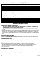
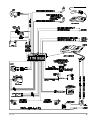
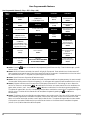
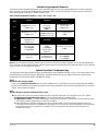
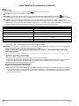
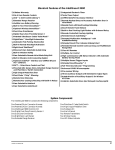
Standard Features of the Arrow 3
n Lifetime Warranty
n Smart Remote Trunk Release
n His & Hers Remote Controls
n User-Selectable AutoArming
n ACG™ 2 (Anti-CodeGrabbing™)
n AutoArm & Lock
n Extended Range Receiver
n Instant AutoArm Bypass
n Audible Low Transmitter Battery Warning
n Patented Malfunction AutoBypass™ with
AutoReMonitoring
n Built-In Starter or Ignition Immobilizer
n Patented SmartPowerUp™ 2
n Optional Wireless Immobilizer™
n Multiple-Car Control
n FACT — False Alarm Control and Test
n Eight-Event TotalRecall™
n Remote Siren Silencing
n Patented Smart Prior Intrusion Attempt Alert
n Piezo Sensor™
n Patented Remote Control Code Learning and
n Dual-Mode “Chirp” Silencing
MultiRemote Recognition
n Patented UltraSecure Coded Valet Mode™
n Clear All Remotes
n Optional DataPort™ Interface to Your Own PC
n High-Luminescence LED Status Parking with Automatic
Battery-Saving Mode
n Point-and-Click Feature Programming
n Complete System Diagnostics At-A-Glance
n Full-Time SecureAccess™ Programming
n High-Output Siren
n Advanced CMOS Microcomputer
n Remote Door Locking/Unlocking*
n Pre-Loomed Wiring
n Remote Panic with Smart Locking/Unlocking*
n Accessory Channel with Selectable Output Type
n Built-In Dual Parking Light Flasher with Onboard Relay
n Installer-Selectable Door Ajar/Delayed Courtesy Lights
n Remote Controlled Courtesy Lighting Output
n Prewired LED, Sensor and PlainView 2 Switch
n Remote Keyless Entry and Accessory Activation Even in
Connectors
Valet Mode
n Patented Smart AutoTesting™
*Programmable (+) or (-), may require relays.
System Components
The Arrow 3 installation kit contains the following components:
One Prewired 20-pin connector harness
One Arrow 3 Control Unit
One Hardware Kit
One Piezo Sensor
Two Remote Transmitters
One Extended Range Receiver
Arrow 3/199
One High Output Siren
One PlainView 2 Coded Valet Switch
One Prewired LED
One User’s Manual
Two Clifford Window Decals
1
Wiring Description for the 20-pin Connector
Pin Wire Color
Connects to
1
2
3
4
5
6
7
8
9
10
11
12
13
14
15
16
17
18
19
20
Door trigger input (+) or (-)
Valet Switch input (-)
Sensor input trigger zone (-)
Trunk and hood trigger input (-)
Sensor input warning zone (-)
LED output (+)
Ignition Input
Ground for the Piezo Sensor, optional sensor and LED connectors, Valet Switch
Battery Negative
Power for the Piezo Sensor, optional sensor
Interior light output (-)
Door lock output + or (-)
Door unlock output + or (-)
Armed output (-)
Accessory Output A (-)
Siren output (-)
Parking light output (+)
Parking light output (+)
Battery positive with 20 Amp fuse
Battery positive with 5 Amp fuse
Gray
White
Orange
Gray/Yellow
Blue
Violet
White/Brown
Black
Black
Red
Brown/White
Gray/Green
Gray/Orange
Green
Gray/Violet
Yellow
Brown
Brown
Red/White
Red
Passenger Compartment Connections
Control Unit and Extended Range Receiver
The Arrow 3 control unit must be installed inside the vehicle. Under no circumstances should the unit be
installed under the hood or other similarly hostile environment.
1. Select an area behind the dash to mount the control unit using wire ties, but do not permanently affix it until all wiring and testing
is complete.
2. Plug the extended range receiver in to the control unit. Mount the extended range receiver away from the control unit and run
the antenna either up the window pillar and affix it to the windshield, or under the dash, away from metal. The position and
location of the receiver will effect remote control range. Do not fold the excess cable or antenna wire. Do not make hard, sharp
bends.
Door Trigger/Interior Light Supply
Please refer to the Door Trigger/Interior Light Supply section in this binder for information on polarity testing and connections.
Central Door Locking System
Please refer to the Door Locks section in this binder for information on circuit types and connections. When adding an IntelliStart 4
to the Arrow 3, it is recommended that RPM-depending door locking be selected. The RPM-dependent door locking feature is only
available with the addition of the IntelliStart 4.
LED Status Indicator
Select a prominent location on the dash or console visible through all windows. Discuss placement with the owner.
1. Verify there is adequate space to accommodate the LED, then drill a 5/16” (8mm) hole and route the wires through it.
2. Mate the LED connectors to the VIOLET and BLACK wire connectors as shown in the diagram on page 3.
3. Press the LED into place.
PlainView 2 Coded Valet Switch
1. Discuss placement of the switch with the vehicle owner and avoid placing the switch where it can be pressed accidentally. It
should be placed in a location that is easily accessible to the driver.
2. Verify there is adequate space behind the selected location to accommodate the switch.
3. Drill a 5/16” (8mm) mounting hole, then insert the wires through the hole and mount the switch.
4. Mate the switch’s locking connectors to the WHITE and BLACK locking connector.
5. Remove the adhesive backing and press into place.
2
Arrow 3/199
Arrow 3/199
3
Passenger Compartment Connections
Piezo Sensor
Mount the Piezo Sensor in the passenger compartment, not in the engine compartment.
1. Firmly mount the sensor near the base of the steering column (if the steering column has a rotating sleeve, firmly screw the sensor
to the interior firewall, kick panel or trunk wall). Make certain that the adjustment screw is accessible.
2. Mate the sensor to the connector on the wireloom with the BLACK, RED, and ORANGE wires.
NOTE: The Arrow 3 also has a dual zone input for an optional sensor.
Trunk Trigger
Vehicles with a ground-switching trunk light will interface directly with the Arrow 3 (on positive switching Rolls-Royce vehicles, use a
relay to invert polarity). The switch may be located in or near the trunk latch or at the trunk light. If a switch cannot be located, you
must add a pin switch in a location away from water channels.
NOTE: If the vehicle has a dashboard trunk ajar indicator, install a 1A diode between the light and switch with
the diode band pointing toward the switch.
1. Connect the GRAY/YELLOW wire to the trunk switch (between the diode and switch if you added a diode).
Parking Light
See the Door Trigger/Parking Light section in this binder.
Accessory Output A with Selectable Output Type and AutoActivation
The Accessory Output A output (GRAY/VIOLET wire) can be programmed as either pulsed, latched or timed and can be
programmed to operate only when the system is disarmed (e.g., for use as a remote trunk release). Accessory Output A output is
activated by pressing the
button on the remote control. The factory setting is pulsed output (0.5 second ground). The latched
output stays at ground until the
button is pressed a second time, and the timed output stays at ground for any selected duration
between one second and four minutes. See Installer-Programmable Features on page 9 for information on programming the output type
and/or disabling operation while the system is disarmed. This circuit can also be programmed to auto-activate every time the system
is armed using the remote control. Current is limited to 0.15 amp. AutoActivation is perfect when programmed as a timed-output to
close the power windows and sunroof on vehicles that have an all-close feature. See the programming instructions on page 7 for
more information on programming output type and/or enabling the AutoActivation feature.
Starter or Ignition Immobilization Circuit
Either the starter or ignition circuit can be disabled with the Immobilizer.
NOTE: The starter circuit may carry a very high current. Be certain that the starter wire connections are solid.
To interrupt the ignition circuit:
1. Locate the ignition switch wireloom under the dash and use a voltmeter to locate the one wire that carries +12V throughout
BOTH the cranking AND engine running cycles, and 0 volts when the ignition is off.
2. Start the engine, then cut the ignition wire. The engine should stop running.
3. Connect the WHITE/RED wire and WHITE/BROWN wire to the key side of the cut ignition line.
4. Connect the other WHITE/RED wire to the ignition side of the cut ignition line.
To interrupt the starter circuit:
1. Use a voltmeter to locate the one wire that carries +12V during the cranking cycle ONLY.
2. Cut this wire, then try to start the engine. It should not crank.
3. Connect the WHITE/RED wire to the key side of the cut starter line.
4. Connect the other WHITE/RED wire to the starter side of the cut starter line.
5. Locate the ignition switch wireloom under the dash and use a voltmeter to locate the one wire that carries +12V throughout
BOTH the cranking and engine running cycles, and 0 volts when the ignition is off.
6. Connect the WHITE/BROWN wire to this wire.
4
Arrow 3/199
Engine Bay Connections
High Output Siren
Mount the siren in the engine compartment away from hot or moving parts and where it cannot be reached from under the vehicle,
preferably opposite the exhaust system. Point the siren down to avoid water collection (see the illustration).
1. You must firmly secure the siren to the engine bay firewall or an inner wing using all three sheet metal screws supplied.
2. Using the supplied connector, connect the wireloom’s YELLOW wire to the BLACK siren wire.
3. Connect the RED wire through the 5A fuse coming from the battery positive cable clamp, as indicated in the diagram on page 3.
Hood Trigger
Vehicles with a ground-switching hood light will interface directly with the Arrow 3 (on positive switching Rolls-Royce vehicles, use a relay
to invert polarity). The switch may be located in or near the hood latch or at the hood light. If a switch cannot be located, you must
add a pin switch in a location away from water channels.
NOTE: If the vehicle has a dashboard hood ajar indicator, install a 1A diode between the light and switch with
the diode band pointing toward the switch.
1. Connect the GRAY/YELLOW wire to the hood switch (between the diode and switch if you added a diode).
Final Wiring Connections
1.
2.
3.
4.
Connect the RED wire to the 5A fuseholder as shown on page 3.
Connect the RED/WHITE wire to the 20A fuseholder as shown on page 3.
Attach the two fuseholders to the battery positive cable clamp.
Attach the BLACK wire to the vehicle battery negative cable clamp.
NOTE: Power and test accessories after the basic system has been tested. Individually fuse all accessory power
connections. Individually fuse all +12V connections.
SmartPowerUp™ 2
SmartPowerUp 2 ensures that the system powers up in the same state (disarmed, armed or valet mode) it was last in. When you first power
up the system, it will silently enter its disarmed state.
Delayed Courtesy Lights
Some vehicles have a courtesy light delay or dimming circuit, which interferes with an alarm being able to detect the door trigger upon
remote arming. If the delay or dimming lasts more than 5 seconds, no special connections or testing are needed, simply turn on the Delayed
Courtesy Lights feature as noted in the Installer-Programmable Features section on page 9. Please note that the Door Ajar Warning
feature will not be available.
Remote Control Operation
The Arrow 3 comes with two ergonomically designed remote controls. Up to a total of four Clifford ACG 2 remote controls can be
programmed into the Arrow 3 (older Clifford ACG and non-ACG remotes are not compatible with the Arrow 3). For information
on how to use the remote controls, see the Arrow 3 User’s Manual.
Function
Press Button(s)
Arm/Disarm
Activate Auxilliary Output A*
(usually remote trunk release)
+✱
Silent Arm/Disarm
Optional IntelliStart Accessory*
✱
+✱
Enable/Disable Remote Valet Mode*
Optional SmartWindows 4 Accessory*
+
*These buttons can be assigned to control another Clifford ACG 2
system on another vehicle.
Arrow 3/199
5
FACT—False Alarm Control and Test
The system microprocessor automatically checks for another activated sensor or trigger before sounding the siren a second time, thus
preventing any further false alarms. If you wish to test FACT, simply,
1. Arm the system with the remote control.
2. Wait 10 seconds after the interior light turns off, then trigger the Piezo Sensor to activate the siren.
3. Do not disarm the system, let the siren complete its cycle.
4. Trigger the sensor again. The alarm should be silent.
5. Unlock and open a door. The alarm should sound immediately. You may now disarm.
Eight-Event TotalRecall
The system’s nonvolatile memory records the identity of the last eight activated or malfunctioning triggers and sensors.
NOTE: The CliffNet Wizard Pro Installation software displays the Eight-Event TotalRecall data in a graphical
format.
1.
2.
3.
4.
With the ignition OFF, press and hold the unmarked side of the PlainView 2 Switch.
Transmit channel 1 to “arm,” and then again to “disarm,” and then release the button.
The LED will flash 1–10 times, pause, then flash 1–10 times, etc. Write down the number of flashes in each cycle.
Refer to the following chart. The first number you wrote down was the most recently activated trigger or sensor. The next number
is the second most recent, and so on up to as many as the last eight activations.
Number of LED flashes between pauses
Trigger/sensor indication
2 flashes
Piezo Sensor or Optional Sensor
4 flashes
Door Trigger
5 flashes
Trunk Trigger/Hood Trigger (trunk only, if IntelliStart 4 has been installed)
6 flashes
Hood Trigger (only if optional IntelliStart 4 has been installed)
7 flashes
An attempt was made to turn on the
ignition or start the engine while the system was armed
10 flashes
System Power Interruption
5. If a sensor is often activated, decrease that sensor’s sensitivity (or reposition the sensor, if necessary). If a certain trigger is often
activated, check pin switch operation, verify that the pin switch is not exposed to moisture and check the trigger wire for possible
shorting.
Programmable Features
Arrow 3 comes from the factory with its features preprogrammed as noted in bold text in the tables on pages 8 and 9. Some features
can be programmed by the installer or the user, others can only be programmed by the installer. There are two tables provided which
define the user-programmable and installer-programmable features.
Using the CliffNet Wizard Pro Installation Software
CliffNet Wizard Pro provides almost intuitive access to all installer and user-programmable features through a user-friendly, graphical
user interface. Because CliffNet Wizard Pro is Windows™-compatible, most operations can be accomplished by simply pointing and
clicking a mouse. CliffNet Wizard Pro totally eliminates complicated programming charts and lengthy programming sequences.
Please refer to the CliffNet Wizard Pro User’s Guide for more programming information if you are using the CliffNet Wizard Pro
Installation software. Otherwise, for manual programming refer to the tables provided in the following sections.
6
Arrow 3/199
Programmable Features (Continued)
Programming the User-Selectable Features
1. Write down the column (across) number and row (down) number of the feature(s) you wish to program.
2. Turn the ignition to the “ON” position or start the engine.
3. Enter the factory preset valet/programming code of “2” by pressing the PlainView 2 Switch’s ✱ button twice, then press the
unmarked button.
4. After entering the code, press and hold the ✱ for about 3 seconds until you hear one siren chirp and the LED turns on to
acknowledge program mode entry. The Arrow 3 is now in the “Feature Select” position for User-Programmable Features.
5. Select the feature column: Press the unmarked button the same number of times as the column number. Pause. You will then hear
the same number of chirps as the column number you have selected, audibly confirming your selection.
6. Within five seconds, select the feature row: Press and release the ✱ button the same number of times as the feature’s row number.
You’ll hear a chirp each time you press the button to help you count.
7. If there is a NOTE for the selected feature, perform the actions noted.
8. Pause. You will hear either one or two chirps: two chirps = ON, one chirp = OFF.
9. You can select another feature, or you can exit program mode:
a. To select another feature in that same column, repeat step 6 within the next five seconds (after five seconds, three chirps
indicate that the Arrow 3 is now back in the “Feature Select” position).
b. To select a different feature column, repeat step 5.
c. To exit program mode, turn the ignition off (you’ll hear three chirps and the LED will turn off to indicate exit of program
mode), or wait 60 seconds and the Arrow 3 will automatically exit program mode.
It may sound a little complicated, but it really isn’t. Briefly, here is all you do: choose the feature you want to change, enter program
mode, select that feature’s column and row, wait for the on/off chirp confirmation, then turn off the ignition. That’s it!
Arrow 3/199
7
User-Programmable Features
User-Programmable Features (1 Chirp = OFF, 2 Chirps = ON)
Feature
Select
Unmarked 1
Unmarked 2
Unmarked 3
Unmarked 4
✱1
Add New Remote
NOTE 1
Chirps
(Off/On/Quiet*)
(1 chirp/2 chirps/3 chirps)
AutoArming
(On/Off)
Arm/Disarm with
Secondary Remote
NOTE 5
✱2
Personalized Siren Sounds*
NOTE 2
NOT USED
AutoArm & Lock
(On/Off)
Trunk Release with
Secondary Remote
NOTE 6
✱3
Play Siren Sounds*
Remote Valet Feature
(On/Off)
NOT USED
Silent Arm/Disarm with
Secondary Remote
NOTE 6
✱4
Siren Duration
(30/60/90 Seconds)
(1 chirp/2 chirps/3 chirps)
NOT USED
FACT
(Off/On)
NOT USED
✱5
AutoLock
(Off/On/RPM)
(1 Chirp/2 Chirps/3 Chirps)
(IntelliStart 4 required for RPM
dependent door locking)
NOT USED
Remote Start with
Secondary Remote
(Requires IntelliStart 4)
NOTE 6
NOT USED
✱6
AutoUnlock
(On/Off)
Clear All Remotes
NOTE 4
NOT USED
Window Rolldown/Venting
with Secondary Remote
(Requires
SmartWindows 4)
NOTE 6
✱7
Reset All to Factory Settings
(except remote controls and
valet code)
NOTE 3
Valet Code
SHOULD ONLY BE PROGRAMMED
BY THE VEHICLE OWNER
NOT USED
Remote Valet Mode
with Secondary Remote
NOTE 6
*Requires Self-Powered SmartSiren 4
button on the remote to be programmed, you will hear one chirp. Press the button again, you will
n NOTE 1: Press the
hear two chirps.
n NOTE 2: When this feature is selected, siren sound 1 will play for five seconds. Press marked to turn the siren sound off,
press unmarked to activate the sound. Next, siren sound 2 will play for five seconds. Press marked to turn the siren sound
off, unmarked to activate it. The system will cycle through all six siren sounds.
n NOTE 3: You will hear two chirps when all features are reset.
n NOTE 4: When you hear two chirps, all remote controls will have been erased from the system memory. You must now add
the new and/or existing remote controls to the system (i.e., AutoProgram each remote that will be used with the Arrow 3).
n NOTE 5: Programs a remote control from any other Clifford system (that uses ACG 2 technology) to arm or disarm the
vehicle. For instance, to set the button
+ ✱ combination of the other car’s master remote control to arm/disarm the
system, select column 4, row 1, then transmit the
+ ✱ button combination from the remote you are programming.
The system will respond with one chirp. Immediately press the button combination a second time. The system will respond
with two chirps. The other vehicle’s remote will now arm/disarm the system by pressing the
and ✱ buttons
simultaneously.
n NOTE 6: This feature can be controlled by a secondary remote or any remote control of any other ACG 2 system, after that
remote has been programmed to arm/disarm this system. Select the row and column number, then transmit the unused
button on the other remote that you want to use to perform that function. The system will respond with the same number
of chirps as the row number. Please note that you must first set a button on the remote that will arm/disarm the system
(column 4, row 1) before these others will be accepted.
8
Arrow 3/199
Installer-Programmable Features
To access the installer-programmable features, use the procedure defined in the User-Programmable section, but after completing
step 4, continue to press and hold the ✱ side of the PlainView 2 Switch for another 10 seconds. You will hear three confirmation
chirps indicating that the system is in installer-program mode.
Table of Installer-Programmable Features: 1 chirp = OFF, 2 chirps = ON.
Feature
Select
Unmarked 1
Unmarked 2
Unmarked 3
✱1
Single/Double Lock Pulse
(1 chirp/2 chirps)
Accessory Output A
Timer Duration
(10 Seconds)
NOTE 1
Door Ajar Warning/Delayed
Courtesy Lights
(1 chirp/2 chirps)
✱2
Single/Double Unlock Pulse
(1 chirp/2 chirps)
Accessory Output A type
(Pulsed/Timed/Latched)
(1 chirp/2 chirps/3 chirps)
Accessory Output A Interlock
(On/Off)
✱3
Lock/Unlock Pulse
1 second/3 second
(1 chirp/2 chirps)
NOT USED
NOT USED
✱4
Door Lock Polarity
Positive/Negative
(1 chirp/2 chirps)
Diesel Engine/Gasoline
Engine
(1 chirp/2 chirps)
(Requires Optional
IntelliStart 4)
AutoActivate Accessory Output A
(On/Off)
✱5
Program RPM (Requires Optional
IntelliStart 4)
Program Optional
SmartWindows 4 or
Learn PageMate 4 ID
Program Door Polarity
(Positive/Negative)
(1 chirp/2 chirps)
NOTE 1: Once this feature is selected, you will hear one chirp to confirm that the timer has started. You can set this anywhere from
one to 4 minutes. When the desired duration has been reached, press the unmarked side of the PlainView 2 switch. You will hear two
chirps to confirm the new system timer duration.
System Checklist & Troubleshooting
The following checklist and troubleshooting tips will assure that you have installed the Arrow 3 correctly. If the system does not react
as noted, follow the troubleshooting tip(s) denoted with a black box below that item, then repeat the step. Each successive step
requires that the previous step has been completed as indicated.
Step 1.
Re-enable the courtesy lights.
In step 1 of the Important Information section (the first tabbed section) in this binder, the interior courtesy lights were disabled.
You must now re-enable the courtesy lights by replacing the fuse you removed or reset the courtesy light switch back to its normal
“DOOR” position before proceeding.
Imm.
Test the Starter or Ignition Immobilization circuit.
n Arm the Arrow 3 (either from inside or outside the vehicle) and wait 10 seconds. Turn the ignition to the “ON” position.
o Engine does not respond and alarm triggers. This is the correct response, proceed to step 3.
o Engine starts or cranks. The starter immobilization circuit has been miswired. Carefully retest the vehicle wires as noted
in the Starter or Ignition Immobilization Circuit section on page 4.
o Engine still starts or cranks after retesting all the wiring as noted on page 4, check the power and ground connections.
Then make sure the fuses are in the fuseholders, verify the control unit connectors are securely fastened, verify the ignition
wires are connected to the true ignition line instead of a 12V or accessory line, and verify that the transmitters are
programmed correctly.
Arrow 3/199
9
System Checklist & Troubleshooting (Continued)
Step 3.
Test the chirps.
Close all doors and arm the Arrow 3 by pressing the
button on the remote control.
n 2 Chirps: This is the correct response. Proceed to step 4.
n 1 Chirp: If you hear only one chirp, the Arrow 3 had previously armed itself passively and by pressing the
button, the
system disarmed (remote disarming is acknowledged with one chirp and one parking light flash). Disarm and rearm the system.
n 4 Chirps: If you hear 4 chirps either immediately or 5-10 seconds after the initial two chirps, a trigger or sensor is open or
active, or the vehicle has delayed courtesy lights and the Delayed Courtesy Lights feature has not been programmed on. Disarm
with the remote control, enter the vehicle and turn on the ignition. The LED will flash 1–10 times, pause, then repeat the same
number of flashes (the flash cycle repeats five times for your convenience). Refer to the following chart.
Number of LED flashes between pauses
Trigger/sensor indication
2 flashes
Piezo Sensor or Optional Sensor
4 flashes*
Door Trigger*
5 flashes
Trunk and Hood Trigger (trunk only, if IntelliStart 4 has been installed)
6 flashes
Hood Trigger (only if IntelliStart 4 has been installed)
7 flashes
An attempt was made to turn the ignition “ON” or start the engine while the system was
armed
10 flashes
Power Interruption
* If the delayed courtesy lights feature is activated, this trigger indication will not be provided.
o If the door trigger is indicated, activate the delayed courtesy lights feature.
n No chirps. If there are no chirps, verify that the Chirps feature (User-Programming - column 2, row 1) is “On” and check the
wiring connections as noted in the High Output Siren section on page 5.
NOTE: If none of the troubleshooting techniques described in steps 3 - 7 corrects the problem, perform the
following diagnostics:
o Make sure the fuses are in the fuseholders.
o Check the power and ground connections.
o Verify that the control unit connector is properly inserted into the control unit.
o Verify that the ignition input and output wires are connected to the true ignition line instead of a 12V line. Find the true
ignition line by following the appropriate steps of the Starter or Ignition Immobilization Circuit section on page 4.
o Verify that the transmitters are programmed correctly.
NOTE: If the 20A fuse blows upon arming:
o Disconnect the Arrow 3’s two parking light wires, replace the 20A fuse and rearm. If the fuse blows while the parking light
wires are disconnected, the door locks are not wired correctly. Reconnect the vehicle’s power locking system to its original
condition, then retest the voltages as indicated in the Door Locks section of this binder and wire the locks as indicated,
then replace the 20A fuse.
10
Arrow 3/199
System Checklist & Troubleshooting (Continued)
Step 4.
Test the parking lights.
Arm the system by pressing the
button on the remote control.
n Two flashes. This is the correct response, proceed to step 5.
n One flash. If the parking lights flash only once, the Arrow 3 had previously AutoArmed itself passively and by pressing the
button the system disarmed (remote disarming is acknowledged with one chirp and one parking light flash). Disarm and
rearm the system.
n No flashes. If no flashes, verify the parking light bulbs are operational. If not, they must be replaced. If so, repeat steps 1-5 of
the Parking Lights section in this binder.
n Only one side flashes. If only the right or the left side parking lights flash, see the Parking Lights section in this binder.
Step 5.
Test the door locks.
Arm the system by pressing the
button on the remote control.
n Doors lock. This is the correct response, proceed to step 6.
n Doors do not lock. You either selected the wrong door lock diagram , connected the wires incorrectly, or a servo may be
required. Reconnect the vehicle’s power locking system to its original condition, then retest the voltages as indicated in the
Door Locking/Unlocking section of this binder and wire the locks as indicated. Polarity programming should also be verified.
WARNING: If the doors do not lock, DO NOT activate the vehicle’s lock switches. If the locks have been
miswired, doing so may damage the Arrow 3 control unit, the vehicle’s electrical system and/or the power lock
servo motors.
n Doors unlock. You either selected the wrong door lock diagram, connected the wires incorrectly, or a servo may be required.
Reconnect the vehicle’s power locking system to its original condition, then retest the voltages as indicated in the Door
Locking/Unlocking section of this binder and wire the locks as indicated.
n Only one door locks. You either selected the wrong door lock diagram, connected the wires incorrectly, or a servo may be
required. Reconnect the vehicle’s power locking system to its original condition, then retest the voltages as indicated in the
Door Locking/Unlocking section of this binder and wire the locks as indicated.
Step 6.
Test the LED.
Arm the system by pressing the
button on the remote control.
n Flashes repeatedly. This is the correct response, proceed to step 7.
n No flashes. If the LED does not flash, verify that the LED’s VIOLET and BLACK wires are solidly connected to the same
color wires on the Arrow 3’s wireloom. Warning: This is a 2-volt LED, testing with 12 volts will destroy the LED.
Step 7.
Test the Valet Switch.
n Test the valet code and switch operation. Use the instructions provided on page 8 to enter programming mode. If the system
enters programming mode, the switch and valet code are in operating order. If not, perform the following tests:
n Check the WHITE/BROWN wire, ignition input is on and verify that it shows +12V when the ignition is turned ON and
+0V when the ignition is OFF. If not, refer to the Starter and Igntion Immobilisation Circuit on page 5.
n Test the WHITE wire at the control unit connector. It should rest at 5 volts. When pressing the marked side, it should read 3
volts and when pressing the unmarked side it should read 0 volts. If any reading is incorrect, move the voltmeter to the
BLACK wire at the valet switch. It should read 0 volts at rest, 0 volts when the marked side marked is pressed, and 0 volts
when the unmarked side is pressed. If the BLACK wire tests correctly and the WHITE wire does not, replace the switch. If
the BLACK wire tests incorrectly, repair the ground circuit. If both wires test correctly, then the valet code has been changed.
Use the CliffNet Wizard Pro to reset the valet code.
Arrow 3/199
11
Step 8.
Test the disarm function.
System Checklist & Troubleshooting (Continued)
n Disarm by pressing the button on the remote control. The following should occur:
o Siren chirps once. If the siren does not chirp once, refer to step 3.
o Parking lights flash once. If the parking lights do not flash once, refer to step 4.
o LED stops flashing. If not refer to step 6.
o Doors unlock. If not refer to step 5.
o Immobilizer circuit immediately disengages (test this by turning the key in the ignition switch; the engine should crank,
start and idle normally). If the Immobilizer circuit does not disengage, refer to step 2.
o Optional interior courtesy light(s) turn on and stay on for 30 seconds or until the ignition is turned on, whichever occurs
first.
o If the interior light(s) do not turn on, verify that you replaced the interior light fuse you removed or have turned the
lights back on as noted in step 1 of this section.
o Make sure that the optional relay is wired correctly.
o Check the door trigger circuit. See step 9 for more information on testing the door trigger circuit.
Step 9.
Test the door trigger circuit.
Rearm the system. Wait at least 10 seconds (if the vehicle has delayed or dimming courtesy lights, be sure to wait at least 10
seconds after the interior lights have turned off). Use the key to unlock and open the driver’s door.
n Siren sounds, parking lights flash repeatedly. This is the correct response, proceed to step 10. (You can silence the siren by
pressing the button on the remote control once or disarm by pressing the button twice.)
n Siren does not sound immediately. If the alarm does not sound immediately when one of the doors is opened, make sure that
that door’s pin switch is working properly and, when open, is consistently showing less than 1.5 volts if the vehicle has
negative-switching door triggers or more than +11 volts if the vehicle has positive-switching door triggers, also make sure the
pin switch is connected to the correct wire. If not, then the door pin switch (or pin switches) is either defective or in need of
cleaning.
Step 10.
Test the trunk trigger circuit.
Arm the system, then use the key to unlock the trunk.
n Siren sounds immediately, parking lights flash repeatedly. This is the correct response, proceed to step 11. (You can silence
the siren by pressing the button on the remote control once or disarm by pressing the button twice.)
n Alarm does not sound immediately. If the alarm does not sound immediately, make sure that the trunk pin switch is working
properly and, when open, is consistently showing less than 1.5 volts. Also make sure the trunk pin switch is connected to the
correct wire. If not, the trunk pin switch must be thoroughly cleaned or replaced, or polarity may need to be inverted.
Step 11.
Test the hood trigger circuit.
Arm the system, then open the hood. The following should occur:
n Siren sounds immediately, parking lights flash repeatedly. This is the correct response, proceed to step 12. (You can silence
the siren by pressing the button on the remote control once or disarm by pressing the button twice.)
Alarm
does not sound immediately. If the alarm does not sound immediately, make sure that the hood pin switch is working
n
properly and, when open, is consistently showing less than 1.5 volts. If not, the hood pin switch must be thoroughly cleaned or
replaced, or polarity may need to be inverted.
Step 12.
Test the AutoArming feature.
Turn the ignition “ON” and let the car idle for a minimum of 10 seconds. Turn the ignition “OFF,” then open and close the door.
Wait five seconds.
n Parking lights flash twice. 25 seconds later, the vehicle arms passively as indicated by a rapidly flashing LED. This is the
correct response, proceed to step 13.
n System does not passively arm.
o Make sure that Instant AutoArming has been turned on using the programming instructions on page 7.
o Verify the door trigger and ignition connections.
12
Arrow 3/199
System Checklist & Troubleshooting (Continued)
Step 13.
Test the AutoArming Bypass feature.
Disarm the system. Turn the ignition to the “ON” position, then turn the ignition “OFF.”
n One Chirp. This is the correct response, wait 30 seconds after the optional courtesy lights have turned off to insure the
system does not passively arm. Proceed to step 14.
Step 14.
Test remote control range.
Stand approximately 40 feet from the vehicle and use the remote control to arm and disarm the system.
n The Arrow 3 will respond with the previously noted indications for arming and disarming. If not:
o Reposition the SuperHeterodyne Extended Range Receiver as high up as possible under the dash or on the windshield and
as far as possible from heavy wirelooms and metal. Rotate the SuperHeterodyne Extended Range Receiver 90 degrees and
re-test.
o Make sure that the remote control battery measures at least 3 volts while transmitting.
o Make sure that the voltage at the control unit between the 5A fused power line and each of the two ground lines measures
at least 12.0 volts (if less, make sure both grounds are solid; if the grounds are solid, the vehicle battery may need charging,
servicing or replacement).
Step 15.
Distribute all necessary paperwork including:
n User’s Manual must be given to the customer.
n Adhere the Clifford window decals to the vehicle’s windows after discussing placement with the vehicle owner.
Step 16.
Demonstrate Basic System Operation:
n Remote control operation:
o Arming/disarming and locking/unlocking
o Panic feature
o Remote Valet Mode
o Accessory Activation
n AutoArming and AutoArming Bypass
n Valet code entry
n User-programming mode
Arrow 3/199
13