1
ASSEMBLY AND INSTALLATION
Assembly of Integrated Controller and Operator Panel
Hole dimensions
For correct installation, observe the dimensions of the
templates shown in the illustration.
The dotted line shows the maximum size of the front panel.
Attention: the panel on which the Integrated Controller and
Operator Panel is mounted has to have the following characteristics:
• be sufficiently stiff and strong so that it does not bend
during use;
• be between 1 and 12 mm thick, to allow the fastening of
the device with the terminals supplied;
• if the use of the USB transfer cable is envisaged, read
the notes on its installation first.
124
187.5
124
93
GF VEDO SL 35CT
187.5
93
GF VEDO SL V70CT
GF VEDO SL V70CT
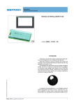
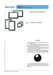
Figure 7 - Panel hole dimensions for GF_VEDO SL
Protection against infiltrations of
water
The Integrated Controller and Operator Panel offers, first of
all, a degree of protection of IP65.
It is therefore possible to install the device in particularly
dusty environments or areas subject to splashes of water
without problems:
• the compartment in which the device is housed also
has to be dust and waterproof;
• the panel on which the device is installed must be perfectly smooth and flat on the front;
• the hole in the panel must scrupulously respect the dimensions indicated;
• the device has to be fastened tightly to the panel, to
allow the gasket fitted at the back to ensure water tightness.
Vibrations
The Integrated Controller and Operator Panel can support
vibrations up to 150 Hz:
• from 5 to 9 Hz: sinusoidal 3.5 mm constant;
• from 9 to 150 Hz: sinusoidal with acceleration equal to
1 G.
Minimum spaces for ventilation
The temperature of the compartment that houses the Integrated Controller and Operator Panel must not exceed 50 °C.
Figure 3 – Free spaces for ventilation shows the minimum
free distances recommended in the installation of the device
in a closed compartment.
Positioning
The Integrated Controller and Operator Panel has to be positioned in order to guarantee the following conditions:
• the screen must not be directly lit by the sun or particularly bright light sources.
• If necessary, screen direct rays, using an antiglare shutter for example;
• there must be no sudden temperature changes;
• there must be a low explosion risk: it can be connected
to elements that operate in environments with a hazardous atmosphere (flammable or explosive) only through
appropriate and suitable types of interface, compliant
to the safety standards in force;
• low presence of magnetic fields.
Should the device be mounted on a support that exceeds
these limits it is necessary to envisage a system for the suspension and mitigation of the vibrations.
21
80989_MAN_G_Cube Fit_10-2012_ENG