1
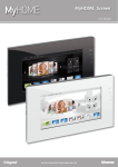
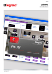
F454 Web Server User Manual 05/12-01 PC Web Server 2 Contents 1 Introduction and basic functions 1.1 Connection modes 1.1.1 Connection to the data network 1.1.2 Remote connection 1.2 Using the Web Server with Web pages 2 Control your home automation system 5 3 Functions to be performed by the administrator 44 6 3.1 Configuration - System 44 6 3.2 Configuration - Language 47 6 3.3 Configuration – Answering system 48 7 11 2.1 Scenarios 12 2.2 Lighting 13 2.3 Automatism 14 2.4 Alarm 15 2.5 CCTV 16 2.6 Answering system 17 2.7 Temperature control 19 2.7.1 Control unit 20 2.7.2 Non-controlled zones 27 2.7.3 External probes 28 2.7.4 Air conditioning 29 2.8 Energy Management 32 2.8.1 Energy data 33 2.8.2 Load management 36 2.8.3 Supervision system 38 2.8.4 Tariff setting 41 3 User Manual Web Server Introduction and basic functions 4 1.1 Connection modes 6 1.2 Using the Web Server with Web pages 7 1 Introduction and basic functions The F454 Web Server gives you the possibility of connecting to your home automation system simply by using a PC and a local (data network) or remote (internet) connection. In this way you can control the various devices (lights, rolling shutters, cameras, etc.) thanks to a Web interface consisting of pages and icons that can be fully customised using a software program. Temperature control Using the “Scenarios”, “Lighting” and “Automatism” applications you can control the lights and rolling shutters of your home or office, and activate scenarios saved in a scenario module, or in scenario control unit. Burglar Alarm Automatism ETHERNET Using the “Alarms”, application you can display any events detected by your burglar alarm system and, by interacting with the “CCTV” application, you can connect to the cameras and the entrance panels of your video door entry system and receive images (you can change the quality, zoom and display settings) and audio feeds. Using the “Answering system” application you can display and/or receive by e-mail the messages (audio and video) recorded by the associated entrance panel. SCS AI CCTV SCS AV F454 Lighting Using the “Temperature control”, application you can control the temperature of your house. Thanks to the “Energy Management”, application you can monitor loads (washing machine, oven, etc.) and display the consumptions of your home. Video door entry system Energy Management 5 User Manual Web Server 1 Introduction and basic functions 1.1 Connection modes 1.1.1 Connection to the data network 1.1.2 Remote connection If the PC is already connected to the network, connection is established by entering the Web Server IP address in the navigation bar of your browser. To access the control page now enter your Login and password details in the user identification page. If the PC is already connected to the Internet, enter the IP address of your own ADSL line in the navigation bar of your browser (ensure that the Modem Router is configured correctly). To access the control page now enter your Login and password details in the user identification page. 6 1.2 Using the Web Server with Web pages Minimum browser requirements for correct display of the web pages: Internet Explorer ver. 7, Firefox ver. 3, Chrome ver. 9, Safari ver. 4. However, for the energy supervision functions, the requirements for Internet Explorer are higher: ver.8 with Google Frame plug-in or better. 1 1 - Enter the Web Server address. 2 - Click to access the identification page. The safety certificate error (certificate issued for a different web site) is due to the fact that the address changes due to the fact that it can be customised by the user. It is therefore impossible to obtain a valid certification for all IP addresses. 2 The browser loads the identification page. 3 - Enter “Login” details and “Password”. 3 Warning: The Web pages can be accessed in two modes: as “user” and as “administrator”. In addition to having access to the same pages as the user, the administrator can also access the “CONFIGURATION” function and define some Web Server parameters, like for example: the number of images to save in the video door entry system answering system, the e-mail address where to forward alarm notifications and/or answering system messages, Login and Password for access to the user pages. etc. Ask your installer for the access password, if not already been provided. 7 User Manual Web Server 1 Introduction and basic functions 4 4 - Click an application to access the corresponding web page. 5 Available applications. 6 Function reserved to the administrator. 7 7 Date and time. 8 System status warnings. 5 8 6 Warning: if no action is performed during the period of time set during the programming procedure, the Web Server takes the user back to the identification page. If a web session is already running, it will not be possible for other users to access the web pages, even if they enter their correct Login and Password details. 8 Example of Web page 1 2 9 8 3 7 4 1 2 3 4 5 Web Server address. Web Server identification name. Available functions. Exit icon. Access to the various pages. 5 6 6 7 8 9 Information and operation area. Selected function icon. Control icons. System status interrogation icon. 9 User Manual Web Server Control your home automation system 10 2.1 Scenarios 12 2.2 Lighting 13 2.3 Automatism 14 2.4 Alarm 15 2.5 CCTV 16 2.6 Answering system 17 2.7 Temperature control 19 2.8 Energy Management 32 2 Control your home automation system Scenarios: this application gives you the possibility of activating the scenarios of your home automation system. Answering system: this application gives you the possibility of listening to any messages from the entrance panel recorded during your absence. Lighting: this application gives you the possibility of switching ON or OFF a certain light or group of light and manage timed ON/OFF light controls. Temperature control: this application gives you the possibility of controlling and adjusting your heating and air conditioning systems, with the possibility of adjusting the temperature in each individual zone, depending on actual needs. Automatism: this application gives you the possibility to manage in a simple way all the automatisms of your home automation system, like rolling shutters, shutters, motorised curtains, etc. Energy Management: this application gives you the possibility of controlling the status of the energy loads, to display energy consumptions/productions, and supervise the electric system. Alarms: this application gives you the possibility of controlling and managing the status of the burglar alarm system. Configuration: This section gives the administrator the possibility of setting the parameters for the use of the Web Server. CCTV: this application gives you the possibility of managing the cameras associated to your home automation system. 11 User Manual Web Server 2 Control your home automation system 2.1 Scenarios The “Scenarios” application gives you the possibility of activating the scenarios of your system. 1 1 - Click the “SCENARIOS” application. The browser loads the “SCENARIOS” page. 2 3 12 2 - Click to activate the desired scenario. 3 A confirmation message appears (Command sent). 2.2 Lighting The “Lighting” application gives you the possibility of switching ON or OFF a certain light or group of lights, and to manage timed ON/OFF light controls. 1 1 - Click the “LIGHTING” application. The browser loads the “LIGHTING” page. 3 4 2 - Click to switch the light ON and OFF. Depending on the devices installed on your system you can also: 5 6 3 Display the status of the Dimmer device. 4 Select the level of the Dimmer device. 2 5 Select the light switch ON time. 6 Select the flashing frequency when switching the light 0N in flashing mode. 13 User Manual Web Server 2 Control your home automation system 2.3 Automatism The “Automatism” application gives you the possibility of managing in a simple way all the automatisms of your home automation system, like rolling shutters, shutters, motorised curtains, controlled sockets, watering system, etc. 1 1 - Click the “AUTOMATISM“ application. The browser loads the “AUTOMATISM” page. 3 2 4 2 - Click to send the UP control (e.g. raise the rolling shutter). 3 - Click to send the DOWN control (e.g. lower the rolling shutter). 4 - Click to stop the current movement. 14 2.4 Alarm The “Alarm” application gives you the possibility of controlling the status of the burglar alarm system. In case of alarm, the message indicates the type (e.g. intrusion alarm, tampering alarm, technical alarm), and the origin (e.g. living room). 1 1 - Click the “ALARM” application. The browser loads the “ALARM” page. 2 3 2 This area can be used to display the alarms: If no alarm events are present, the message “No pending alarm” will be displayed. In case of intrusion alarm the message “Intrusion alarm: <zone name>” will be displayed. 3 In this area it is possible to display if the system is active, the zones connected and the status of the battery and network. In case of intrusion or auxiliary alarms (e.g. gas leak) the Web Server will warn the user by e-mail by sending a text with the alarm warning and the images coming from the camera (if any). The address to which the message should be send to must be set by the administrator in the configuration page. 15 User Manual Web Server 2 Control your home automation system 2.5 CCTV The “CCTV” application gives you the possibility of displaying the images recorded by the cameras or entrance panels connected to the CCTV. By using the icons present on the page the user can interact by selecting the desired camera, change the image parameters, like brightness, contrast, quality, colour, and zoom settings. If the selected camera belongs to an entrance panel, the door lock and the lighting can also be enabled. 1 1 - Click the “CCTV” application. The browser loads the “CCTV” page. 2 3 2 - Click to select the camera to enable. 3 - Click to enable/disable the selected camera. You can also: 4 5 4 Enable door lock and light controls (entrance panel). 5 Switch the framing of the enlarged section horizontally or vertically. 6 Adjust brightness, contrast, quality, colour, and zoom. 6 The CCTV function is disabled while a message is being recorded by the video door entry answering system. 16 2.6 Answering system The “Answering system” application gives you the possibility of displaying images and voice messages from the entrance panels, saved by the Web Server. By using the icons on the page the user listen to/delete message, and select images any images to enlarge them. 1 1 - Click the “ANSWERING SYSTEM” application. The browser loads the “ANSWERING SYSTEM” page. 2 2 - Click to display the images and listen to the message saved. If this function has not been enabled during the configuration stage, it can be enable by clicking the “Activate” icon. 17 User Manual Web Server 2 Control your home automation system 3 3 - Click to enlarge the selected frame (the audio message is repeated). The frame number and other parameters may be configured in the configuration page. 4 You can also: 4 Display the message date and time. 5 Listen to the message. 5 6 7 8 9 18 6 7 8 9 Delete the message. Download the .wav audio file to your PC. Enable/disable the answering system. Display the status of the answering system and the memory % used. 2.7 Temperature control The “Temperature control” application gives you the possibility of controlling and managing your heating and air conditioning systems, with the possibility of adjusting the temperature in each individual zone, depending on actual needs. 1 1 - Click the “TEMPERATURE CONTROL” application. The browser loads the “TEMPERATURE CONTROL” page. The Web page shows four icons: • CONTROL UNIT • NON-CONTROLLED ZONES • EXTERNAL PROBES • AIR CONDITIONING 19 User Manual Web Server 2 Control your home automation system 2.7.1 Control unit In this section you can manage the temperature control unit and the zones of the temperature control system. 1 1 - Click “CONTROL UNIT“. The browser loads the “CONTROL UNIT” page. The functions available are split into three pages: • GENERAL: to check the system status A • PROGRAMMING: to set the system parameters • DIAGNOSTIC: to perform a system diagnostic B GENERAL The “GENERAL” Web page is split in two areas: The top section ( A ) is used to display the operating mode of the control unit and the status of the system (summer/winter/antifrost, etc.); the bottom section ( B ) is used to display the status of the zones. 20 1 2 3 4 5 1 Display of the control unit operating mode. 2 Display of the season set on the control unit (summer/winter). 3 Display of the icons indicating the status of the control unit. 4 Selection of the zones for which to display the parameters. 5 Display of the parameters of the selected zone. 21 User Manual Web Server 2 Control your home automation system PROGRAMMING In this page you can set the parameters of the control unit or zones by clicking on the corresponding items ( A ). Programming – Control unit In this page you can set the parameters of the control unit in the set modes: • Weekly Program Active: Select one of the 3 summer programs and the 3 A winter programs (previously set in the control unit). Your system will operate automatically following the settings defined for the set program. • Scenario Active: select a scenario among the 16 summer ones and the 16 winter ones. Your system will operate automatically following the scenario set. • Weekend Active: it gives the possibility of selecting a certain daily program for a set period. The program is performed up to the programmed date and time, after which the set weekly program will be reactivated. • Holiday Active: this mode can be used to keep the system(in case of extended absence, e.g. holidays) in Antifrost or Thermal Protection mode until the set date and time. After this period the set weekly program will be reactivated. • Set Mode: – Manual: it give the possibility of setting the temperature, with a deviation of half degree; – Antifrost/Thermal protection: temperatures are set to 7° C (antifrost) and 35° C (thermal protection); – OFF: to switch the system OFF. 22 Setting the parameters of the Control Unit/Zones (e.g. set the “Holiday” program) 1 - From the pull-down menu select the program to set at the expiry of the “Holiday” program. 2 1 2 3 2 - Set the end date and time of the “Holiday” program. 3 - Click the icon to confirm the selection. 4 A confirmation message appears (Command sent). 4 It is possible to remotely check that the command has been received and accepted by the control unit. To do this go to the “GENERAL” page and check that the status of the control unit and/or the programmed zone has been amended accordingly. 23 User Manual Web Server 2 Control your home automation system Programming - Zones In this page you can set the parameters for individual zones: • Set Mode: – manual: it give the possibility of setting the temperature, with a deviation of half degree; – antifrost/Thermal protection: temperatures are set to 7°C (antifrost) and 35°C (thermal protection); – automatic: to bring the selected zone back to the mode of operation set on the control unit in case the zone had been forced to a different mode of operation; – OFF: to switch the zone OFF. • Fan-coil: if the sensor is a Fan-coil type, set the fan speed to one of the following: – Automatic; – Minimum; – Medium; – Maximum. 24 • Unlock room sensor settings: with this function you can unlock the settings (off or antifrost/thermal protection) of the individual zone (sensor), if these have been set manually. The mode of operation set on the control unit is reinstated. It is possible to remotely check that the command has been received and accepted by the control unit. To do this go to the “GENERAL” page and check that the status of the control unit and/or the programmed zone has been amended accordingly. 25 User Manual Web Server 2 Control your home automation system DIAGNOSTIC The “DIAGNOSTIC” page gives you the possibility to check the devices in the individual zones, and to notify any anomaly in one or more system zones. The following messages can be displayed: • “No anomaly found” if the system is working correctly. • “System problem” if a problem is found on one or more zones/sensors. This is followed by the list of zones where the fault has been detected and the corresponding descriptions. • “Control unit not responding” if the BUS connection is interrupted, the system power supply has been disabled, or no sensor/zone is able to communicate with the Web Server. 26 2.7.2 Non-controlled zones This section can be used to manage the non-controlled zones installed on your home automation system. 1 - Click “NON-CONTROLLED ZONES“. 1 The browser loads the “NON-CONTROLLED ZONES” page. In this page you can display the temperatures measured in the non-controlled zones (measurement sensor only). 2 - Click to return to the previous page. 2 27 User Manual Web Server 2 Control your home automation system 2.7.3 External probes In this section you can manage the external probes installed on your home automation system. 1 - Click “EXTERNAL PROBES“. 1 The browser loads the “EXTERNAL PROBES” page. In this page you can display the temperatures measured by the external radio probes (measurement probes only). 2 - Click to return to the previous page. 2 28 2.7.4 Air conditioning In this page you can manage the AC units (with interface 3456) of the air conditioning system. 1 - Click “AIR CONDITIONING“. 1 The browser loads the “AIR CONDITIONING” page. Both basic and advanced management are possible (depending of the configuration performed by the installer). In the first case, management is performed using the 20 commands saved in the 3456 interface, while in advanced mode, management is performed directly as if the AC unit remote control was being used. AC Unit – Basic mode Click the activation keys to send programmed commands, or to switch the unit OFF. 29 User Manual Web Server 2 Control your home automation system 1 2 3 1 - From the pull-down menu select an “AC unit”. 2 - Click to send the command. You can also: 3 Switch the AC Unit OFF. 4 A confirmation message appears (Command sent). 4 Select “GENERAL” and click the activation icon to display the page containing the “groups of commands” which, when enabled, send one or more commands to several units at the same time. 1 2 30 1 - Select “GENERAL” from the pull-down menu. 2 - Click to send the group of commands. AC Unit – Advanced mode While in this mode, you can click the activation keys to send programmed commands and switch the unit OFF, and also use the customised function to select and send directly one or more commands, in the same way as if using an AC unit remote control. 1 - From the pull-down menu select an “AC Unit” or the “GENERAL” command. 1 2 - Click to send the customised command. 3 2 4 5 You can also: 3 Send a programmed command. 4 Switch the AC unit OFF. 5 A confirmation message appears (Command sent). As for the basic mode, select general to send groups of commands. 31 User Manual Web Server 2 Control your home automation system 2.8 Energy Management The “ENERGY MANAGEMENT” application gives you the possibility of checking the status of the energy loads, to display energy consumptions/productions and to perform a supervision of the electric system, intervening on the devices for resetting the “salvavita” safety devices. 1 - Click the “ENERGY MANAGEMENT” application. 1 The browser loads the “ENERGY MANAGEMENT” page. The Web page is split into two subpages, “FUNCTIONS” ( A ), and “TARIFF SETTING” ( B ). In the first page you can select the following functions: • ENERGY DATA; • LOAD MANAGEMENT; • SUPERVISION SYSTEM. A 32 B 2.8.1 Energy data This function gives you the possibility to monitor energy consumption and production for the following items: Electricity, water, gas, domestic hot water, heating/cooling. 1 2 1 - Click “ENERGY DATA“. 2 - Click the item to display among: ELECTRICITY: It displays the electricity consumed or produced by the system. WATER: It measures the water consumed. Connect the meter to a water meter with impulse output. GAS: It displays gas consumption. Connect the interface to a gas meter with impulse output. DOMESTIC HOT WATER: It measures the hot water consumed. Connect to a hot water meter, or to the corresponding impulse output of a heat measurement control unit, which can be found in the apartment user modules (in case of central heating). HEATING/COOLING: displays the calories/frigories measured on the heating/ cooling system. Connect to a meter with heat impulse output (KWh). 33 User Manual Web Server 2 Control your home automation system This manual only describes the Electricity control feature. All energy controls are managed in the same way. 3 3 - Click the meter for which you want to display consumptions. This page displays energy consumptions/productions in a chart or table format. The details may be displayed as daily, monthly, or annual figures. 4 6 In this page you can: 5 9 4 Set the display period. 5 Display the consumption chart. 7 8 10 6 Display the consumption table. 7 Switch consumption display from energy units to monetary units. 8 Export the data in a .CSV format. 9 Select the type of display between DAY/MONTH/YEAR. 10 Click to return to the “Electricity” page. 34 - In this page you can also compare two meters to display the balance between energy consumption and production in the system. 11 12 11 Select the meters to compare. - 12 Click the icon to check the balance. - This page shows the balance between consumption and production in a chart and a table format. 35 User Manual Web Server 2 Control your home automation system 2.8.2 Load management When a load management control unit is installed, this function gives you the possibility to control the power engaged, in order to prevent the power meter from cutting the power off, by excluding the loads based on the priorities set by the installer. If the installed actuators allow it, you can check the load consumptions. 1 - Click “LOAD MANAGEMENT“. 1 Load management with control unit As for the previous page, you can display the information page to check the power engaged by the loads. When the central unit detects a system overload, the load with the lowest priority level is disabled and the icon is displayed; 2 - Click to enable the load again. It is possible to exclude the control of a load by the control unit for a set period of time (default 2 hours and 30 minutes). In this way the load cannot be disabled by the control unit. 3 Load excluded from the control of the control unit. 2 4 - Click to put the load back under the control of the control unit. 5 Set the time during which the load is excluded from the control of the control unit. 3 4 5 6 7 6 - Click to exclude from the control of the control unit. If the control unit detects that the set load limit is still being exceeded, the load in question will still be disabled. 7 - Click to check the consumption of the load. 36 8 Select the loads 9 Reset the meter 8 9 Load management without control unit 1 1 - Click to check the consumption of the load. 2 Select the loads 3 Reset the meter 2 3 37 User Manual Web Server 2 Control your home automation system 2.8.3 Supervision system This page can be used to select the sub-page for the control of Stop & Go devices, as well as the page controlling that the system loads are operating correctly. 1 - Click “SUPERVISION SYSTEM“. 1 The browser loads the “SUPERVISION SYSTEM” page. The Web page shows two icons: • STOP & GO • LOAD DIAGNOSTIC 38 STOP & GO Depending on the type of reset on the system, it will be possible to send different types of commands. 2 2 - Click “STOP & GO”. The browser loads the “STOP & GO” page. 3 6 7 4 5 – Stop and Go In this mode you can enable or disable the automatic reset function. 3Enable/disable automatic reset – Stop and Go plus This mode can be used to force reset if the Stop and Go device is open. A system test can also be enabled or disabled. 4Enable/disable the system test 5Forced reset – Stop and Go btest This mode can be used to enable or disable the Autotest function. It is also possible to set the Autotest frequency (number of days between tests). 6Stop and Go Autotest 7Autotest frequency 39 User Manual Web Server 2 Control your home automation system LOAD DIAGNOSTIC This page can be used to check that the loads are operating correctly by measuring the earth leakage current absorbed by the same. 1 - Click “LOAD DIAGNOSTIC”. 1 The browser loads the “LOAD DIAGNOSTIC” page. The load is operating correctly. The load is operating correctly, but the earth leakage current is close to the limits of the standards. The earth leakage current exceeds the limits of the standards, causing the opening of the Stop & Go device. 40 2.8.4 Tariff setting This function can be used to set the tariff for each type of energy control. 1 - Click “TARIFF SETTING”. 1 The browser loads the “TARIFF SETTING” page. 2 2 - Click to select the item. 41 User Manual Web Server 2 Control your home automation system 3 42 4 3 - Set the tariff. 4 - Click to save the data entered. Functions to be performed by the administrator 3.1 Configuration - System 44 3.2 Configuration - Language 47 3.3 Configuration - Answering system 48 43 User Manual Web Server 3 Functions to be performed by the administrator 3.1 Configuration - System This section (access reserved to the administrator) includes the configurations to be performed by administrator users. 1 - Click the “CONFIGURATION” application. 1 The browser loads the “CONFIGURATION – SYSTEM” page. 2 3 • C ANSWERING SYSTEM • SYSTEM - CONFIGURATION 5 6 44 B • A SYSTEM • B LANGUAGE 4 A This page is split in three subpages based on the type of configuration to be performed: 7 In this page the user with administrator authority can configure the login and password details for normal users (2), the recipient of e-mail messages (3), the enabling of the password for the remote display of the cameras in safe mode (4) and the Ethernet configuration parameters for access to the Web Server (5). 6 - Click to confirm the data entered. C 7 - Click “DATE/TIME” to go to the corresponding page and configure the date, the time, and the time zone. • SYSTEM – DATE/TIME 8 8 - Insert Date/Time and time zone. 9 - Click to confirm. 10 Click ”DIAGNOSTIC” to display the page containing the parameters of the device and the diagnostic message (e.g.: No anomaly detected). 9 10 • SYSTEM - DIAGNOSTIC Device parameters 12 Click here to perform an update. 12 13 - 13 Click “IP RANGE” to display la page where the user can enter- the range of IP addresses of the devices that must connect to the Web Server without the need for the OPEN password. 45 User Manual Web Server 3 Functions to be performed by the administrator • SYSTEM – IP RANGE 14 15 46 14 Enter the range of addresses. - 15 Click to confirm the data entered. - 3.2 Configuration - Language 1 - Click “LANGUAGE”. 1 The browser loads the “LANGUAGE” page. In this page the user with administrator authority can set the language for the display of the Web pages of the Web Server. 2 2 - Select the desired language. 3 - Click to confirm. The Web pages will be displayed in the new language. 3 If the system is busy performing other operations a message asking the user to wait will appear. 47 User Manual Web Server 3 Functions to be performed by the administrator 3.3 Configuration – Answering system 1 - Click “ANSWERING SYSTEM”. 1 The browser loads the “ANSWERING SYSTEM” page. 4 2 In this page the user with administrator authority can configure: The number of photos (from 1 to 16) that will be saved at every call from the entrance panel (2); select, if required, the voice presentation message (3); enable/disable the video door entry system answering service (4). 3 If the system is busy performing other operations a message asking the user to wait will appear. 48 Details of the icons and the functions performed 1 Number of photos that can be saved by the Web server for the answering system service. 1 2 3 2 Confirmation icon. 3 Icon used to play the message locally. 4 Field used for entering the presentation message name. 4 5 6 5 Access to the PC folder containing the presentation messages (.wav file). 6 Icon used to forward the message to the Web Server. 7 8 7 % indication of the memory used. 8 Answering system enabling/disabling icon. The video door entry system answering system messages can be retrieved from web pages and can be forwarded as an e–mail attachment to a set e-mail address. The attachment will be a compressed .zip file containing image files in .jpg format and audio files in .wav format. 49 User Manual Web Server BTicino SpA Via Messina, 38 20154 Milano - Italy www.bticino.com BTicino SpA reserves at any time the right to modify the contents of this booklet and to communicate, in any form and modality, the changes brought to the same.