1
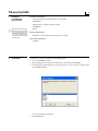
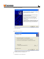
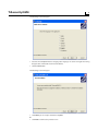
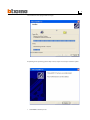
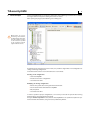
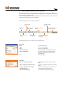
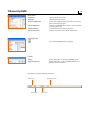
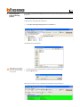
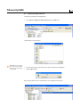
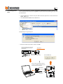
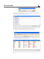
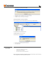
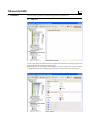
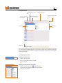
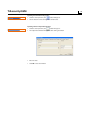
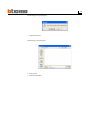
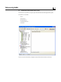
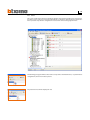
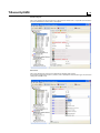
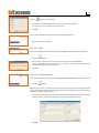
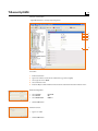
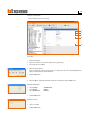
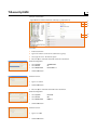
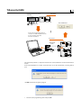
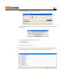
05/08 - CT
Software for the configuration
of the 3486 Burglar Alarm Unit
TiSecurityGSM user manual
Version 1.0
CONTENTS
1. Hardware and Software requirements
4
2. Installation
4
3. Basic concepts
8
3.1 Menus and general buttons for selecting functions
4. Importing data from an existing project
11
4.1 Importing voice messages
4.2 Importing configuration data
5. Connecting to the Unit
13
6. Exchanging data with the Unit
15
7. Parameters
16
7.1 Work area
7.1.1 Data input procedure
7.2 Exchanging configuration parameters with the Unit
7.2.1 Receiving configuration parameters
7.2.2 Sending configuration parameters
7.2.3 Receiving the history of events
7.3 Configuration of the Burglar alarm section
7.3.1 Zones
7.3.2 Automations
7.3.3 User Preferences
7.3.4 Installer Preferences
7.3.5 Key management
7.3.6 Scenarios
7.4 Configuration of the Dialling device section
7.4.1 Telephone number directory
7.4.2 Setting up calls
7.4.3 Telephone functions
7.4.4 Block (Lock)
7.4.5 Protocol - MyHome Portal
7.4.6 Protocol - ADEMCO
7.4.7 Line test
7.4.8 GSM Management
7.4.9 Telephone commands
8. Messages
50
8.1 Work area
8.2 Exchanging voice messages with the Unit
8.2.1 Sending voice messages
8.2.2 Listening to messages from the Unit loudspeaker
8.2.3 Receiving voice messages
8.3 Voice message commands
8.3.1 Importing an audio file
8.3.2 Emitting a voice message
8.3.3 Recording a voice message
8.3.4 Retrieving voice messages
9. Update Firmware
54
TiSecurityGSM
1. Hardware
and Software
requirements
Please note: The TiSecurityGSM program is the essential
tool for the configuration of
the 3486 Burglar alarm Unit.
The content of this program
is under the exclusive rights
of Bticino SpA.
Hardware requirements
• Personal Computer with Pentium processor >400 MHz
• 256 MB RAM
• SVGA graphics card with resolution 800x600
• CD-ROM unit
• Mouse
Software requirements
• Windows 2000, XP or Vista; Internet Explorer 6.0 or higher.
Space used on hard-disk
• 91 Mbyte.
2. Installation
Follow this procedure to install the TiSecurityGSM program:
1. Insert the CD-ROM in the drive;
2. After displaying the main page in the web format, select “Install TiSecurityGSM”;
3. The installation program will now copy the system files necessary for the execution of the
TiSecurityGSM program.
> Select the installation kit language
> Click the Ok button
The following screen will appear
> Click the Next button
The following screen will appear
> Click Next to install the program in the default directory
“c:\Programmi\BTicino\TiSecurityGSM_0100”
Or
> Click Browse to select the required path
TiSecurityGSM
The following screen will appear
> Select the TiSecurityGSM interface language (The language can also be changed when using
the application, without the need for reinstallation).
> Click the Next button
The following screen will appear
> Click Next if you are ready to install TiSecurityGSM
Or
> Click Back to return to the previous screen
The installation of the program will now begin.
Depending on the operating system setup in use, it may be necessary to restart the system.
> Click Finish to end the process
TiSecurityGSM
3. Basic concepts
The TiSecurityGSM software is used for the configuration of the 3486 Burglar alarm Unit which combine
the burglar alarm and telephone dialling device into one device.
After opening the program, the following screen will appear:
Please note: For proper
functioning of the software,
the 3486 Burglar Alarm Unit
must be installed according
to the indications specified
in the installation manual
supplied with the device.
Depending on the technician and user’s needs, it is possible to begin with a new configuration or
change an existing configuration.
In this manual the various screens will refer to the second mode.
Creating a new configuration:
• Start TiSecurityGSM
• Execute and save the configuration
• Send data to the Unit
Modifying an existing configuration:
• Execute the system auto-learning function from the Unit
• Receive data from the Unit with TiSecurityGSM
• Edit, if required
• Send data to the Unit
In order to perform a proper configuration, it is necessary to execute the system auto-learning
function before connecting the Unit to the PC.
Using the Firmware Update function, with the TiSecurityGSM it is also possible to update the permanent Control Unit Software, using new issues published by BTicino.
3.1
Menus and general buttons for selecting functions
The main functions that can be executed with TiSecurityGSM can be selected by using the icons in
the toolbar or by opening drop-down menus, thus selecting the various options. Quick keys can
also be used for some functions, like:
to create a new project, it is possible to select New from the File drop-down menu, from the toolbar
and from the keyboard by using the keys Ctrl +N.
The followings functions are included in the toolbar:
Save the current
project
Create a new
project
Opens an existing
project
Opens the Parameters section
Select the interface
language
Executes connection to
the Unit
Opens the Voice
message section
Executes connection to
the Bticino website
Selects the serial port of
the PC to which the Unit is
connected
The followings functions are included in the drop-down menus:
“File” menu
• New
• Open
• Save
• Save as (with name) • Export configuration
creates a new project
opens an existing project
saves the current project
saves the project after requesting a file name
exports the project thus creating a file with
extension .csv which can be imported into
Microsoft Excel®.
• Exit
exits the program
“Edit” menu
• Import messages from project
imports all voice messages from an existing
project
• Import configuration data from project
imports all configuration data from an existing
project
• Load pre-defined audio messages
• Select all messages
• Select all fixed messages retrieves voice messages set up for the Unit
selects all messages of the project
selects all fixed messages of the project
TiSecurityGSM
10
“Tools” menu
• Parameters
• Messages
• Receive configuration
opens the Parameters section
opens the Messages section
receives the configuration from the Unit, it is active only
when connecting to the Unit
• Send configuration
sends the configuration to the Unit, it is active only when
connecting to the Unit
• Update Firmware
• Connection to Unit
starts the Unit firmware update procedure
enables connection between the PC and the Unit
“Language” menu
•
select the TiSecurityGSM interface language
“?” menu
• About...
• Supported versions
displays information on the TiSecurityGSM program
displays information on TiSecurityGSM, hardware and
software versions of the Unit
The status bar shows the following information:
Current data
Current time
Loaded project file
Type of Unit
11
4. Importing data
from an existing
project
It is possible to import data (configuration parameters and voice messages) from a previously saved
project file.
4.1
Importing voice messages
To import voice messages from a project file:
> Select Import messages from project from the Edit menu
The following screen will appear
Please note: it is recommend
to save the current configuration file of before starting
the procedure.
> Select the project file (. jai) from where you want to import the messages
> Click the Open button
When the procedure has been completed, the imported messages will appear
TiSecurityGSM
12
4.2
Importing configuration data
To import a previously saved configuration:
> Select Import configuration data from project from the Edit menu
The following screen will appear
Please note: it is recommend
to save the current configuration file of before starting
the procedure.
> Select the project file (. jai) from where you want to import the configuration
> Click the Open button
When the procedure has been completed, the new configuration will appear
13
5. Connecting to the
Unit
To access some functions (e.g. Receive configuration, Send messages, etc.) there must be a connection between the PC where TiSecurityGSM is installed and the Unit, following the operation
described below.
> From the Port menu, select the serial port address of the PC you want to connect the Unit to
(COM1, COM2, etc.).
> Select Connection to Unit from the Tools menu
The following message will appear
> Execute the required operations and then click OK
Select the maintenance menu of
the Unit and start the auto-learning function
Slide switch
MAINTENANCE
Language
Key program
System test
Learning
Flip the slide switch to off
Click the OK button
Connect the programming cable to a
serial port or USB of the PC and to the
6–way connector of the Unit
Item 335919
Item 3559
impianto
on
off
TiSecurityGSM
14
At this stage, by clicking the Details button, it is possible to display the list of communication activities between the personal computer and the unit.
When connecting to the Unit, a comparison will be made between the configuration of the Unit
which reflects the real system, and the configuration of the current project.
If the configurations are different, the following warning message it will appear:
> Click Yes to display the details of the differences found
The data can be exported into a file with extension .csv, which can be imported in Microsoft
Excel.
15
> The following message will appear if click QUIT
> Click YES to load the configuration of the system in the Unit
> Click NO to keep the current project unchanged
However, there will be a connection to the Unit.
At the end of the procedure the Connection button will change into Disconnection.
It is now possible to swap data with the Unit
Click Disconnection to stop connection.
The following message will appear
> Disconnect the programming cable from the Unit
> Click the OK button
6. Exchanging data
with the Unit
When the connection to the Unit has been activated, it will be possible to:
•
•
•
Send/receive configuration parameters
Send/receive voice messages
Receive the history of events from the unit
Refer to paragraphs “7.2 Exchanging configuration parameters with the Unit” and “8.2 Exchanging
voice messages with the Unit” to carry out these functions.
TiSecurityGSM
7. Parameters
16
In this section it is possible to execute the Unit parameters configurations.
7.1
Work area
In this section all typical parameters for the configuration of the Unit are displayed, represented
hierarchically with a tree structure on the left side.
On the right side, a specific template for inputting data and, if the connection is active, for communicating with the Unit can be displayed by selecting each element of the hierarchic structure.
17
Data input template
Send configuration to the
Unit
Receives configuration
from the Unit
Displays information
Receives the history of
events from the Unit
Fixed zone
Communication bar with
the Unit
Data input
zone
Help zone
The upper bar includes the commands for communication with the control unit (only active when
the connection with established PC); the central section is for data entry, and will vary depending
of the selected parameter; the lower bar displays the instructions to guide the user through the
data entry procedure.
7.1.1 Data input procedure
Inputting by typing in data:
> Click the data input zone
> The text, if any, will be edited (e.g. Input)
> Type in new data
Inputting data with the drop-down menu:
> Click the data input zone; the
button will appear
> A drop-down menu will appear after clicking the button
> Select any data available
TiSecurityGSM
18
Inputting data with the sliding menu:
> Click the data input zone; the
button will appear
> Use the button to move through the available data
Inputting with an independent window:
> Click the data input zone; the
button will appear
> An independent window will appear after clicking the button
> Enter the data
> Click OK to close the window
19
7.2
Exchanging configuration parameters with the Unit
7.2.1 Receiving configuration parameters
This function allows you to receive the configuration parameters from the Unit.
> Execute the Connection to Unit procedure
> Click Receive button
The following screen will appear
> Click the Yes button
If the current project has not been saved, a reminder appears on the screen.
> Click the Yes button
When the procedure has been completed, the Unit configuration parameters will be available in
the relative section for future verifications or changes.
To activate a new configuration the sending procedure, described in the following paragraph, must
be completed.
TiSecurityGSM
20
7.2.2 Sending configuration parameters
This function allows you to send the configuration parameters to the Unit.
> Execute the Connection to Unit procedure
> Click Send button
The following screen will appear
> Click the Yes button
If the current project has not been saved, a reminder appears on the screen.
> Click the Yes button
When sending the parameters, a comparison will be made between the configuration of the Unit
and the configuration of the current project, if these are different the following warning message
will appear:
21
Click Yes to display all differences found.
When No is clicked (or Quit in the error window), the following message apperas:
> Click the Force button to send the parameters of the current project to the Unit and then modify
its configuration.
> Click the Align button to change the parameters of the current project, thereby aligning them
with the configuration of the Unit.
TiSecurityGSM
22
7.2.3 Receiving the history of events
This function allows you to receive the history of events. This is the chronological list of all events
occurred on the burglar alarm system, and recorded by the Unit.
> Execute the Connection to Unit procedure
> Click Event memory button
The following screen will appear
> Click the Yes button
When the procedure has been completed, you will see a window showing the list of events recorded
by the Unit in the history of events.
> Click the Export button to export the event memory into a file
23
The following message will appear:
> Click the Yes button
The following screen will appear:
> Name the file
> Click the Save button
TiSecurityGSM
24
7.3
Configuration of the Burglar alarm section
In this section it is possible to set up the part of the Unit related to the burglar alarm system.
The options are as follows:
• Zones
• Automations
• User Preferences
• Installer preferences
• Scenarios
The tree structure will show the configured components with their number in brackets.
25
7.3.1 Zones
This screen shows the list of zones in which the burglar alarm system is divided. For each zone it is
possible to enter a reference name which identifies it (eg. Entrance). Entering the description of a
zone is possible only after the configuration of at least one device belonging to this zone.
The following paragraphs will describe how to set up devices in different zones; to perform these
configurations, the device must be present.
The present devices will be displayed in red.
TiSecurityGSM
26
Common objects
This screen displays the devices which are common to the whole unit. It is possible to indicate the
presence of the device and to enter a description.
Connectors
This screen displays the connectors included in the burglar alarm system.
It is possible to signal the presence, activate, enter a description and select the type of connectors
among the available ones.
27
Zones 1...8
This screen displays the devices included in the single zones.
It is possible to signal the presence, activate, enter a description and select a type of device.
Furthermore, it is possible to enable/disable the activation delay the device can be delayed or
not depending on the type of device selected and on its firmware version.
When you click the Information button, you will see a screen which will show how the delay time
will be set up for the devices of the zone.
TiSecurityGSM
28
Auxiliaries
This screen displays the devices which are not included in the burglar alarm system (e.g. gas leak
detector).
It is possible to signal the presence, activate, enter a description and select a type of device.
29
7.3.2 Automations
This screen shows the list of automations that can be set up (Max. 20).
The automation lets you link an execution (set with an Open command) to one specific burglar alarm
event.
It is possible to enable/disable the automation, enter a description and select an event to be matched
with an execution to produce the automation required.
Event Field
Data input field
Event
Depending on the choice made, it is possible to select a type of event from the Type drop-down
menu; the underlying fields will be activated and dealt with later on.
Data input
Click Run to display the Open Configuration window. This can be used to define the Open Configuration (manually or using the guided procedure) for the selected event.
Guided Insertion:
> Select the Open Command and select the data related to the system, to the action and to the
destination.
> Click the Ok button
TiSecurityGSM
30
Manual Insertion:
> Type in the Open Web Net code to create the Open Command
> Click the Ok button
Type of event - Alarm
> Select the type of event from the drop-down menu
Type of event - Technical
> Select the type of event from the drop-down menu
Type of event - Power lack
> Select the type of event from the drop-down menu
Type of event - Enable/Disable (Insertion/De-insertion)
> Select the type of event from the drop-down menu
The associated field will be activated by selecting the Scenario event
> Click the
or
button to select the desired scenario
31
Click the
button to set the division
> An independent window will be opened, select the zones to be divided
No scenarios can be set if there are no active zones.
> Click Ok
The associated field will be activated by selecting the Connector event
> Type in the connector number
Type of event - Date
The associated field will be activated by selecting the Date event from the drop-down menu
> Click the
button
> Enter the date and time for the activation of set automatic event in the Run field.
To set an automatic event to run every day at a certain time, enter ** in the Day/Month/Year
fields, and then the Hour and the Minutes.
> Click Ok
Type of event – Event from system
The associated field will be activated by selecting Event from system from the drop-down menu.
> Click the
button
With this type of event it is possible to match two data inputs (open-open): the first through the
independent window which can be activated from the Event field whereas the second as per the
other type of event from the Run field.
> An independent window will be opened, enter the Open Command using the guided configuration procedure, or by directly entering the instruction in the Manual section.
> Click Ok
TiSecurityGSM
32
Example of automation
- Lights ON in “Room 3” at every trespassing alarm.
1
2
3
4
5
Procedure:
1
2
3
4
5
Enable automation
Type in the reference name of the automation (e.g. Staircase lights)
Select type of event - Alarm
Select Intrusion event
Enter the Open command which will activate the automation after the Intrusion event
Guided Configuration:
> Select System
> Select Action
> Select Destination
> Click the Ok button
Manual Insertion:
> Type in *1*1*3##
> Click the Ok button
LIGHTING
ON
ROOM 3
33
Example of automation
- Lower the blinds at 22:30 h every day.
1
2
3
4
5
Procedure:
1 Enable automation
2 Type in the reference name of the automation (e.g. Evening)
3 Select type of event - Date
4 Enter the date and time
To set an automatic event to run every day at a certain time, enter ** in the Day/Month/Year
fields, and then the Hour and the Minutes.
> Click the Ok button
5 Enter the Open command which will activate the automation after the Date event
Guided Configuration:
> Select System
> Select Action
> Select Destination
> Click the Ok button
Manual Insertion:
> Type in *2*2*0##
> Click the Ok button
AUTOMATISMS
DOWN
GENERAL
TiSecurityGSM
34
Example of automation
- Lights OFF Room 4 when the blind is rolled up (e.g. light point 11).
1
2
3
4
5
Procedure:
1
2
3
4
Enable automation
Type in the reference name of the automation (e.g. Day)
Select type of event – Event from system
Enter the Open command which will activate the automation.
Guided Configuration:
> Select System
> Select Action
> Select Destination
AUTOMATISMS
UP
LIGHT POINT 11
> Click the Ok button
Manual Insertion:
> Type in *2*1*11##
> Click the Ok button
5 Enter the Open command which will be the automation.
Guided Configuration:
> Select System
> Select Action
> Select Destination
> Click the Ok button
Manual Insertion:
> Type in *1*0*4##
> Click the Ok button
LIGHTING
OFF
ROOM 4
35
7.3.3 User Preferences
This screen displays the user’s preferences.
It is possible to change all preferences in the procedures described hereinafter.
It enables you to enter or change the user code of the Unit.
In the basic configuration the user and maintenance code are the same; they also enable you to
access all menus of the Unit.
Changing the user code will also automatically update the maintenance code as long as the latter
is not modified.
> Type in the user code in the required field
Sets the duration of the siren sound in case of an alarm due to tampering or problems related to
the SCS signal reception.
> Select one of the proposed values from the drop-down menu
Sets the duration of the siren sound in case of an alarm.
> Select one of the proposed values from the drop-down menu
Assigns the delay time for the activation of the sensors of zone 1. This allows you to pass through
zone 1 before disconnecting the system and without activating the alarm.
> Select the delay duration from the drop-down menu
Assigns the delay time for the activation of the sensors of zone 1. This allows you to pass through
zone 1 after enabling the system and without activating the alarm.
> Select the delay duration from the drop-down menu
Adjusts the display contrast of the Unit.
> Adjust the contrast with the arrows by clicking in the field
TiSecurityGSM
36
7.3.4 Installer Preferences
This screen displays the installer’s preferences.
It is possible to change all preferences in the procedures described hereinafter.
Adjusts the display language of the Unit as well as the voice messages.
> Select one of the proposed languages from the drop-down menu
It enables you to enter or change the installer code (maintenance code).
In the basic configuration the user and maintenance code are the same; they also enable you to
access all menus of the Unit.
This function enables you to distinguish them in order to allow only the installer to access the
Maintenance menu of the Unit.
> Type in the maintenance code in the required field
Enables/disables the ON (3 flash) and OFF (1 flash) signaling (through the flash of the external siren)
of the burglar alarm system.
> Select Yes/No from the drop-down menu.
Enables/disables the periodic check of the interconnections between the Unit and devices connected
> Select Activ./Deactiv. from the drop-down menu.
Sets the unit as a Master clock (sends the time update to all MyHome devices provided with a
clock, such as Touch Screen, Web Server, etc.) or as a Slave (receives the time update from other
devices).
Only one device of the MyHome system can be set as a Master.
> Select Master/Slave from the drop-down menu.
Activate/deactivate the audible signal at entry, exit, or both.
37
7.3.5 Key management
The programmed keys on the Control Unit can be customized using this menu. The following functions can be customized:
- key enable/disable
- ID name allocation
- combination with a scenario key or with a certain division
- limitation of the use of the key to certain weekdays and/or to a certain time band.
After programming the keys on the Control Unit, establish the PC connection and click “Receive”,
to transfer the configurations of the keys to the TiSecurityGSM unit.
Enables/disables the use of the key
Enter a name for the key, so that its use can be easily checked in the event memory
It indicates the type of key programmed on the Control Unit: IR remote control, keypad or
transponder
TiSecurityGSM
38
It can be used to link one of the sixteen programmable division scenarios, or, in alternative, a specific
division, to the key (see following paragraph).
If the system is armed with the key programmed, the scenario or the division linked to the key will
become active.
Click
to open the drop-down menu for the selection of the division scenario
To set a division not set as a scenario, select Division and click
the zones present in the system. The ones showing the
to deactivate them.
No scenarios can be set if there are no active zones.
. A window will appear, showing
symbol are active. Click on the symbol
By default, the keys are enabled to be used at all times. It is however possible to limit their use
depending on the user needs.
In the example below, the use of the key has been limited to 8.30 to 11.30, Mondays and Thursdays.
39
7.3.6 Scenarios
Up to sixteen division scenarios can be created in this section. These can be selected by the user,
depending on specific needs, using the Control Unit keypad.
Enables/disables the scenario
Enter a name for the scenario (e.g. perimeter)
Select Division and click
. A window will appear, showing the zones of the system, marked
with the
symbol. The symbol indicates that the zones are active, and can be clicked to activate
them.
No scenarios can be set if there are no active zones.
TiSecurityGSM
40
7.4
Configuration of the Dialling device section
In this section it is possible to set up the part of the Unit related to the Telephone Dialling Device.
The options are as follows: :
• Telephone number directory
• Set calls
• Telephone functions
• GSM management
• Telephone controls
The tree structure will show the configured components with their number in brackets.
41
7.4.1 Telephone number directory
In this screen it is possible to set up the jolly number and the 10 telephone numbers of the directory.
Jolly number
It is the first telephone number called by the Unit when any type of alarm is detected (intrusion,
failure, technical alarm).
If the MyHome portal is enabled, make sure the Jolly number matches the telephone number of
the portal.
If the ADEMCO protocol is used, the jolly number must be the surveillance unit number.
It is possible to enable/disable, enter a description and a telephone number.
Telephone number 1...10
It is possible to store the 10 telephone numbers of the directory in these fields. The numbers of
the directory entered will be able to be used (e.g. for being included in the 4 numbers to be called
according to the type of alarm recorded by the burglar alarm system – see “Outgoing calls”), only
if enabled in this template.
It is possible to enable/disable, enter a description and a telephone number.
TiSecurityGSM
42
7.4.2 Setting up calls
Please note: the telephone
numbers to be matched will
appear in the drop-down
menus only if previously
enabled in the telephone
number Directory screen
This screen lets you match some telephone numbers stored in the directory with the alarm events
detectable by the burglar alarm or any specific Open event chosen by the user.
When a specific even occurs, the Control Unit will call the set phone number and communicate the
type of alarm that has occurred using a voice message (see chapter “Messages”).
Calls following a System alarm event and System failure
> Enable/disable the event
> Select the telephone numbers of the directory to be matched with the event from the drop-down
menu (max. 4 numbers)
Calls following an Open event
> Enable/disable the event
> Type in the reference name
> Enter the OPEN command which will initiate the call
> Select the telephone numbers of the directory to be matched with the event from the drop-down
menu (max. 4 numbers)
43
7.4.3 Telephone functions
This screen displays the telephone functions that can be customized.
It is possible to change all functions in the procedures described hereinafter.
Enables/disables the dialling device to make telephone calls.
> Select Yes/No from the drop-down menu
If this function will be disabled and if a protocol (MyHome Portal or ADEMCO) is active, the following
message will appear:
> Click the Yes button
The function is now “Enabled for outgoing calls” and the “MyHome Portal” service is disabled.
Sets the number of rings, after which the dialling device answers a call.If there’s an answering machine, the number of rings shall be higher than the one set for the answering system.
> Select the number of rings from the drop-down menu
Determines the number of times the dialling device will repeat calls to the numbers from which it
did not receive an answer.
> Select the number of cycles from the drop-down menu
TiSecurityGSM
44
Sets the delay time, following an alarm, before the call cycle is started.
> Select the delay time from the drop-down menu
Allows you to set the type of line.
> Select DTMF (tone dialling line) or PULSE (pulse dialling line) from the drop-down menu
Sets the time between the moment power goes off and the starting time of the Unit telephone
calls.
> Select the waiting time from the drop-down menu
Enables/disables the management of the burglar alarm system from the telephone line.
> Select from the drop-down menu:
USER: Remote control can only be performed by the user.
MANAGER: Remote control can only be performed by the Surveillance Unit.
ON: Remote control can be performed by the User and by the Surveillance Unit.
OFF: Remote control is disabled.
Informs the dialling device that an answering machine is installed on the telephone line.
> Select Yes/No from the drop-down menu.
Enables/Disables the possibility to send remote voice messages to the room (via the Unit loudspeaker and if connected from the sound system) and the room listening function via the Unit
microphone.
> Select Yes/No from the drop-down menu.
Assigns the waiting time between one call and the next.
> Select the waiting time from the drop-down menu
Enables/disables entry remote assistance calls for the surveillance units using the ADEMCO protocol.
Remote assistance is only possible if the 3486 control unit is in “System Test” mode.
> Select Yes/No from the drop-down menu
Enables/disables entry remote assistance calls for the surveillance units using the ADEMCO protocol.
Remote assistance is only possible if the 3486 control unit is in “System Test” mode.
> Select Yes/No from the drop-down menu
45
7.4.4 Block (Lock)
In this screen it is possible, through the options available in the “Enabling” drop-down menu, to decide not to lock the open commands remotely, to lock all of them or to set up to 4 Open commands
that cannot be performed remotely.
> Select type of lock from the “Enabling” drop-down menu
If you select “Customized” it will be possible to define the filters described hereinafter.
> Enter a description for the filter
> Enter the Open command you
want to lock.
TiSecurityGSM
46
7.4.5 Protocol - MyHome Portal
This screen displays the setups for managing the system through the MyHome portal.
> In Type select MyHome Portal.
> Type in the password OPEN to access the system.
> Type in the System identifier provided by the MyHome portal
After enabling the My Home Portal, if the Control unit is not “Enabled for out calls”, the following message will appear:
> Execute the operations described in the message and repeat the operation
When the My Home Portal is enabled, the Jolly number must be the portal telephone number.
47
7.4.6 Protocol - ADEMCO
This setting enables automatic sending of alarm notifications and events to the surveillance unit
using the Contact ID protocol.
> In Type select ADEMCO Service
> Enter the ADEMCO ID supplied by the surveillance unit
Please note: the ADEMCO
protocol can only be activated if the Control unit is
“Enabled for out calls”
> Select the surveillance service level (refer to the table)
Ademco
level
Events signalled to the Surveillance control unit
1
Intrusion, anti-panic and tampering alarms
2
As level 1 + system signals (e.g. battery flat, power cut)
3
As level 2 + technical alarms (auxiliary commands)
4
As level 47 + switching ON and switching OFF events
TiSecurityGSM
48
7.4.7 Line test
The Control unit can be set to check the good working order of the telephone line at set times and
intervals.
> Set the frequency for the completion of the test
> Enter the Test Start Hour and Minutes.
7.4.8 GSM management
In this screen it is possible to enter the Pin Code of the SIM card inserted in the 3486 GSM Unit.
If the SIM card does not need a Pin Code, do not change the setup (basic “0000”).
49
7.4.9 Telephone commands
In this screen it is possible to set up telephone commands which can later be executed by the user
through simplified codes consisting of just 4 digits, through the Unit keypad or by telephone.
> Enable/disable the command
> Type in the reference name
> Enter the command open code.
In this case, by remotely typing in the command 9911, the user will switch on the entrance lights
whereas if 9901 is typed in, they will switch off.
The user can record a personalized voice message only for the first 4 telephone commands (see
chapter “Messages”).
TiSecurityGSM
8. Messages
50
In this section, it is possible to manage voice messages which are sent from the Unit to the set
telephone numbers when a particular event occurs or as an answer to telephone commands sent
by the user.
8.1
Work area
The screens in the “Messages” section display the messages related to the type selected in the bottom
menu (fixed Messages, Presentation, customizable Calls, telephone Commands); it is possible to
select the various templates by clicking the corresponding buttons.
The screens are divided into two columns: the tree-structured Message column includes the messages whereas in the Content column it is possible to enter a name which identifies the message.
The messages will have a green background.
At the top part of the screen there is a message management bar and at the bottom there is a zone
where there will be different information related to the selected message.
Sends a message to
the Unit
Receives all messages
from the Unit
Emits a message from the
Unit loudspeaker
Imports an
audio file
Stops emitting/recording a
message
Emits a message
Records a
message
Message (message length)
Example of the message voice contents
Description of the message function
51
8.2
Exchanging voice messages with the Unit
8.2.1 Sending voice messages
This function allows you to send one or more messages to the Unit.
> Execute the Connection to Unit procedure
> Select by ticking the box next to the message to be sent
or select all messages
> Choose Select all messages from the Edit menu or
Select all fixed messages as needed
> Click Send from the message management bar
wait until the procedure has been completed
TiSecurityGSM
52
8.2.2 Listening to messages from the Unit loudspeaker
This function allows you to listen to the message selected from the Unit loudspeaker.
> Execute the Connection to Unit procedure.
> Select a message; the message will be highlighted.
> Click Listen from the message management bar
The message will be emitted from the Unit loudspeaker.
8.2.3 Receiving voice messages
This function allows you to receive all messages included in the Unit.
> Execute the Connection to Unit procedure
> Click Receive from the message management bar.
The following message will appear
Please note: the messages in
the current project file will be
overwritten.
> Click the Yes button
When the procedure has been completed, the Unit voice messages will be available in the Messages
section for future verifications/changes, if required.
53
8.3
Voice message commands
8.3.1 Importing an audio file
This function allows you to import an audio file.
> Select a message; the message will be highlighted.
> Click Import wav from the message management bar
The following screen will appear
> Select the audio file (. wav) from where you want to import the messages
The installation directory includes the folder “Wave”, in which the voice messages are con-tained
and divided into folders according to the language.
The audio file must have the following features:
- maximum duration as per description (... sec.)
- type .wav
- sampling: PCM 8Khz
- resolution: 8 bit Mono
> Click the Open button
8.3.2 Emitting a voice message
This function allows you to emit a message from the PC loudspeaker
> Select a message; the message will be highlighted.
> Click Listen from the message management bar. the message will be emitted
> Click Stop from the message management bar to stop
8.3.3 Recording a voice message
This function allows you to record a message
>
>
>
Select a message; the message will be highlighted.
Click Record from the message management bar
Start recording by speaking in a normal voice from a microphone connected to the PC
The recording will automatically end when the preset time for the message has elapsed.
8.3.4 Retrieving voice messages
This function allows you to retrieve voice messages set up for the Unit
> Select Load pre-defined audio messages from the Edit menu
The pre-defined audio messages will be retrieved by overwriting those of the current project.
TiSecurityGSM
9. Update Firmware
54
This function allows you to update the permanent basic software (firmware) in the unit through
revision procedures distributed by Bticino
> Select Update Firmware from the Tools menu
The Download Firmware screen will appear
Stops the update
procedure.
It is activated after
loading the file
Opens an
update file
Update file loaded
Exits the
screen
Selects the serial port
of the PC to which the
Unit is connected
Starts the update procedure.
It is activated after loading the file
Displays a template containing information about the
Firmware
Displays log of activities
executed while
downloading
The above commands are also available in the File and Tools drop-down menu.
> Click the Select file button
55
The following screen will appear
> Select the update file (.fwz)
> Click the Open button
The Update button is now available
> From the Port drop-down menu, select the serial port of the PC you want to connect the Unit to.
> Click the Update button
The following message will appear
Execute the required operations and then click OK
TiSecurityGSM
56
Select the maintenance menu
of the Unit
Slide switch
MAINTENANCE
Language
Key program
System test
Learning
Flip the slide switch to off
Click the OK button
Connect the programming cable to a
serial port or a USB of the PC and to the
6–way connector of the Unit.
Press the reset button.
Reset button
Item 335919
(serial)
impianto
on
off
Item 3559
(USB)
The application performs a comparison between the selected firmware and the Control Unit firmware.
If the selected firmware is an older version than the one on the Control Unit, a warning will appear.
click NO to terminate the update program
> Disconnect the programming cable and press OK
57
If the selected firmware is a more recent version than the one on the Control Unit, the update
procedure will continue without any other messages.
When the update procedure has been completed, the following message will appear along with
an audible alert
> Disconnect the programming cable from the Unit
> Click the OK button
> Press the Unit reset button.
The Unit firmware is now updated.
Once the updating process has been completed it is possible, by clicking on Detail, to display a
window which lists the activities carried out during the firmware download operation.
Bticino SpA reserves at any time the right to modify the contents of this booklet and to communicate,
in any form and modality, the changes brought to the same.
BTicino SpA
Via Messina, 38
20154 Milano - Italy
www.bticino.it