1
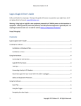
Thermoelectric Generator
Final Report
April 28, 2010
Kevin Jensen
Drew Messick
Jeremy Verzosa
Table of Contents
Requirements Specification .......................................................................................................................... 3
Project Overview........................................................................................................................................... 5
Introduction .............................................................................................................................................. 6
Budget Analysis ......................................................................................................................................... 7
Block Diagram ........................................................................................................................................... 8
Functional Description of Blocks............................................................................................................... 9
Sub System Details ...................................................................................................................................... 11
Thermosyphon ........................................................................................................................................ 12
Thermoelectric Generator ...................................................................................................................... 13
Cooling System ........................................................................................................................................ 14
User Interface and Inverter..................................................................................................................... 15
Encasement............................................................................................................................................. 20
Testing Results ............................................................................................................................................ 21
Recommendations ...................................................................................................................................... 22
Appendices.................................................................................................................................................. 23
Appendix A: Thermosyphon Parts .......................................................................................................... 24
Appendix B: Thermoelectric Generator Parts ......................................................................................... 25
Appendix C: Cooling System Parts .......................................................................................................... 26
Appendix D: User Interface and Inverter Parts ....................................................................................... 28
Appendix E: Encasement Parts ............................................................................................................... 30
2
Requirements Specification
Background: There is a large interest in today’s market for sustainable energy. Consumers are looking
for devices that can provide electricity to their home, not only when power is unavailable but also in
addition to their normal usage. The trouble with most products is that they are complex, bulky and
expensive. Additionally, energy sources for these generators are not always available (wind/solar/fossil
fuels).
What is needed is a low cost, storable, easy to use device that provides supplemental energy to
the home or emergency electricity if the power is out. We believe that a generator using an already
built fireplace as the energy source is the natural choice for this request. The major benefit of this
generator is that the combustion chamber is already available and safe, users know how to use it and
fuel is readily available.
The Deliverables: There are five deliverables as listed below:
1. Working Prototype
2. System Specifications
a. Design Concept
b. Block Diagram
c. CAD Drawing and Analysis
3. Circuit Schematics and Simulation Results
4. User’s Manual
5. Bill of Materials
Principles of Operation: The user will begin by installing the generator to their existing fireplace. The
device will not be permanent, but instead will be installed only when used. The actual generator will sit
on the hearth outside of the fireplace. A device will extend into the fireplace to collect heat and
transport it to the generator. Once a fire is built and the chamber reaches a sufficient temperature the
generator will begin to produce electricity and notify the user that they can plug in a device. The user
will then be able to plug in any electrical device which uses less than 150W of power to a standard
NEMA Type B outlet.
Special Restrictions: The generator must be considered safe with no parts exposed that could cut or
burn the user. Additionally, the electrical aspects should present no risk of fire or shock. The NEMA
Type B outlet should be properly grounded.
Input: The input of the device is a wood burning fire in an open hearth fireplace. The heat from the fire
will serve as the energy source for the electric generator. Closed stoves and gas burning fireplaces will
not be supported.
3
Output: The generator’s output connector will consist of a NEMA Type B electrical outlet. The outlet
will provide 125 VAC േ 15% and at least 1.5 A േ 10% at 60 Hz േ 0.5%. For comparison, most normal
household electrical outlets in the United States provide approximately 125 volts and 15 amps at 60 Hz
when connected to the power grid.
Technical Requirements: The following requirements must be met.
1. Size – The device should be small and light enough to be carried by a single person. The
generator should be no greater than 0.6 x 0.6 x 0.46 meters (2 x 2 x 1.5 feet). This does not
include the device for collecting and transporting heat from the fire to the generator.
2. Weight – The device should not weigh more than 22.7 kg (50 lbs).
3. Installation – The generator will sit on the hearth and a device will be extended into the fire for
heat collection. There will be no permanent attachments such as bolts or screws to be affixed
prior to use.
4. Harmful Gases – The device should not compromise the existing effectiveness of the fireplace to
route harmful gases (carbon dioxide, carbon monoxide, nitrogen oxides and aldehydes) out from
the house. Due to the large variety of sensors needed along with the associated costs, this will
be judged by visually observing if there is a change to the amount of smoke in the room when
the device is in use compared to when it is not in use.
5. Nature of Fuel – The device will work with a fire built with wood logs (not wood chippings or
sawdust). The user will not be required to cut the logs to certain dimensions, provided the logs
will fit in the fireplace.
6. User Intervention – The user will be responsible for maintaining the fire. An indicator on the
device will notify the user if the fire is not hot enough (sufficient power is not being produced;
see Indicators and Controls). The device should not require the user to burn more than 25
pounds of wood per hour.
7. Indicators and Controls – The device will indicate visually (e.g. LED) to the user when enough
electricity is being generated to run a device. Additionally, the user will be able to cut off power
to the outlet by shutting off the device with a switch.
8. Electrical Safety – The electrical system must be grounded by a connection to an existing wall
outlet’s ground. All internal wires should be able to handle the maximum amount of current in
order to prevent electrical fires. Wire that is at least an AWG gage 10 nonmetallic insulated wire
will provide this safety.
9. General Safety – Any exposed (outside of the fireplace) surface of the device should not exceed
43 degrees Celsius (110 °F) in order to prevent burning the user.
4
Project Overview
5
Introduction
The team set out to design a low cost, storable, easy to use device that provides supplemental
energy to the home or emergency electricity if the power is out. The device that the team designed sits
on an existing fireplace hearth and uses the heat from the fireplace as an energy source. The wood
burning generator answers the call for a sustainable, small, simple home energy source.
The design of the wood burning generator went
through three main stages. Each stage was defined by
breakthroughs or changes in the method of heat transport. In
the first stage (shown in Figure 1), a heat pipe was to be used to
transport heat from the fireplace to the device. This approach
was simple and required little effort of the part of the user.
However, the design proved above the skill level of the team.
The second stage (shown in Figure 2) was ushered in when
Figure 2: Stage 1 Design
serious design began. A thermosyphon was chosen as the best
way to transport the heat and the design was
changed accordingly. Rather than one pipe entering
the fireplace two were needed; one for steam and
one for water returning to the boiler. The third and
final stage began when the desired pressure of the
thermosyphon boiler was reduced from 180 psi to 1
psi. This change greatly increased the safety of the
project while allowing the theory to still be tested.
Construction began during the spring
semester. Unfortunately, some design changes were
made during this time resulting in increases to
Figure 1: Stage 2 and 3 Design
research and development costs. Many of these
changes simplified the final result and brought down the actual manufacturing cost as well as making a
better product. Construction was completed with some time to spare. Initial testing of the system
yielded electrical problems which were fixed before the prototype was ready for unveiling.
The system as a whole worked as designed. The thermosyphon successfully transported heat
from the fireplace to the thermoelectric generators, and the cooling system effectively cooled the other
side of the thermoelectric generators. Unfortunately, the thermoelectric generators were not able to
produce enough power to charge the battery and power the fans due to the steam temperature of the
thermosyphon being lowered. By using an external power source for the fans, the circuit was
successfully used to charge the battery with the thermoelectric generators.
The wood burning generator project was an excellent test for the mechanical and electrical
engineering skills of the team members. Despite challenges and setbacks encountered during both
design and construction the team delivered a prototype which satisfied seven out of nine technical
requirements and came very close to satisfying the other two (size and weight).
6
Budget Analysis
The team’s total budget for producing a working prototype of the wood burning generator was
set at $850. The team ended the year having spent a total of $841.01 leaving $8.99 left over in the
contingency fund. The actual cost for producing the device was found to be $695.16. Mass producing
the device could bring this cost even lower.
The research and development cost of the wood burning generator is broken down by
subcomponent in Table 1. The actual production cost is shown in Table 2.
Table 1: Research and Development Cost by Sub Function
Sub Function
Original
Thermosyphon
$55.00
Thermoelectric Generator
$215.00
User Interface
$65.00
Inverter
$60.00
Cooling System
$70.00
Encasement
$35.00
Current
$324.35
$205.36
$113.65
$47.22
$113.20
$37.23
Contingency
$350.00
$8.99
Total
$850.00
$850.00
Table 2: Production Cost by Sub Function
Sub Function
Original
Thermosyphon
$55.00
Thermoelectric Generator
$215.00
User Interface
$65.00
Inverter
$60.00
Cooling System
$70.00
Encasement
$35.00
Current
$194.85
$205.36
$104.61
$47.22
$113.20
$29.92
Contingency
$350.00
$154.84
Total
$850.00
$850.00
The team came close to going over budget, but through judicious spending and careful choice of
parts and vendors the total cost was $841.01 with $8.99 left over.
7
Block Diagram
Encasement Boundary
Fireplace
100° C < T < 500° C
Thermosyphon
95° C < T < 100° C
User Interface
Hot Side
Heat Sink
95° C < T < 100° C
8
Thermoelectric
Generator
Excess heat
(100° C without cooling)
Cooling Device
12 VDC, 20 mA
14.6 VDC,
0.6 Amps
Battery
12 VDC, 18 A
Inverter
120 േ 10 VAC
A > 1.5 Amps
60 േ .05 Hz
Unit Outlet
8
Functional Description of Blocks
Fireplace – The user’s fireplace acted as the combustion chamber and contained the wood burning fire.
The fire provided temperatures between 100° C and 500° C. The fireplace performed as expected and
successfully supplied heat to the thermosyphon.
Input: Wood
Output: Temperatures between 100° C and 500° C
Thermosyphon – The thermosyphon collected heat from the fire in a boiler changing liquid water to
water vapor which then exited the fireplace and delivered temperatures ranging from 95° C to 100° C.
The vapor condensed in copper coils, was stored in the holding tank and then returned to the boiler.
The thermosyphon went through many changes throughout construction (see Thermosyphon section
for more information), but performed as anticipated. Improvements could be made by increasing the
pressure of the boiler and therefore the temperature of the steam which would increase the energy
production of the thermal electric generators.
Input: Temperatures between 100° C and 500° C
Output: Temperatures between 95° C and 100° C
Hot Side Heat Sink – The hot side heat sink transferred the heat from the thermosyphon to the hot side
of 10 thermoelectric generators (40mm x 40mm each). It was maintained at temperatures between 95°
C to 100° C.
Input: Temperatures between 95° C and 100° C
Output: Temperatures between 95° C and 100° C
Thermoelectric Generator – The thermoelectric generator used the temperature differential that
existed between the hot side heat sink and the cold side heat sink to produce approximately 14.6 volts
and 0.6 Amps DC or 8.76 Watts (ten individual thermoelectric generators providing approximately 1.5
Volts and 0.60 Amps each assuming a temperature differential of 50° C, all ten placed in series). The
thermal electric generators did not produce the amount of power initially expected of them. However,
this was due to changes in the thermosyphon. Additional thermoelectric generators or an increase in
thermosyphon temperature could potentially increase power output.
Input: Temperature between 95° C and 100° C
Output: 14.6 Volts and 0.60 Amps DC (8.76 watts)
Excess heat (100° C without cooling)
9
Cooling Device - The cooling device removed approximately 2149 W or more of heat from the
thermoelectric generators. This was achieved through forced convection by two fans over ten finned
heat sinks. The cooling device successfully cooled one side of the thermoelectric generators. The
system might be improved with larger heat sinks or heat sinks made of material with great heat
conductance (e.g. copper)
Input: Excess heat (100° C without cooling)
Output: > 2149W heat removed.
Battery – The battery was charged by excess DC voltage produced by the thermoelectric generator. It
served as a regulator as the output of the thermoelectric generator fluctuated.
Input: 14 V and 23 A DC (322 W)
Output: 12.7 V and 18 A DC (228.6 W)
Inverter – The inverter converted the DC power from the thermoelectric generator or battery into AC
power and stepped up the voltage.
Input: 12 V and 18 A DC (216 W)
Output: 120 10 VAC, greater than 1.5 Amps, 60 ± 0.05 Hz
User Interface – This circuitry controlled the flow of power to the outlet as well as indicated to the user
when sufficient power was being supplied to the outlet. When the user switch was in the on position,
power was available and the user could plug in a device using 200 watts or less. When it was in the off
position, no power was supplied to the outlet. Additionally, a single indicator LED would light up when
at least 12 volts was being supplied by the battery. The user interface worked as expected except for
the low power output of the thermoelectric generators. If the power output from the thermoelectric
generators could be increased, then the battery could be charged while operating the fans. The inverter
needed to be run from the battery alone. However, the thermoelectric generators simultaneously
charged the battery.
Input: 12.7 V DC and 1.5 A, 60 ± 0.05 Hz
User controlled switch
Output: LED indicator
Unit Outlet – The unit outlet was a standard household outlet (NEMA type B) that the user plugged their
device into. Originally, the neutral pin was to be connected to the metal frame of the device. However,
during construction the encasement material was changed to wood and it was determined that the
outlet was safe without this extra precaution.
Input: 110 VAC – 125 VAC, greater than 1.5 Amps, 60 ± 0.05 Hz
Output: 110 VAC – 125 VAC, greater than 1.5 Amps, 60 ± 0.05 Hz
10
Sub System Details
11
Thermosyphon
The purpose of the thermosyphon is to transfer heat from the fireplace to the thermal electric
generators. This is done by boiling water in a boiler located inside of the fireplace. The steam produced
then travels to a heat exchanger where the energy is transferred to the thermal electric generators. Any
remaining steam is then condensed in copper tubes and eventually recycled back into the boiler.
The design of the thermosyphon consists of three main parts. The boiler is located in the
fireplace and facilitates liquid water being turned in to water vapor. The thermal electric condensing
chamber and the condensing tubes extract energy from the steam and return it to the liquid phase. The
holding tank stores this water and allows the user to refill the boiler starting the process over again. A
boiler gage allows the user to know the temperature and pressure of the boiler.
Many of the design changes throughout the spring semester were driven by safety concerns.
There are many standards that affect boiler design and boiler safety that were unknown during initial
design. Due to this, the operating pressure of the boiler was reduced from a gage pressure of 150 psi
(1034 kPa) to 1 psi (6.9 kPa). This significantly increased the safety of the device, but drastically lowered
the temperature of the hot side of the thermal electric generators (from 180° C to 100° C). To
accommodate this change, an available 1 psi check valve replaced the 150 psi pressure relief valve. To
further increase safety, a boiler gage reading both temperature and pressure was added to the front of
the device.
Thermoelectric
Generator Condensing
Chamber
Holding Tank
Boiler Gage
Pressure Relief/Check
Valve
Boiler
Condenser
Figure 3: Thermosyphon
The thermosyphon was tested successfully independently and as a component within the larger
system. The water in the boiler successfully boiled from this input and was able to pressurize the boiler
to 1 psi (6.9 kPa). The temperature of the copper pad on which the thermal electric generators sit was
measured at approximately 95 - 99°C. The piping between the thermal electric condensing chamber
and the boiler also measures a similar temperature. The condensing tubes were tested to ensure that
they were long enough and that only liquid water would exit at the end.
The thermosyphon was a major component of the wood burning generator. During
construction a lot of extra time was devoted to ensuring that it would work successfully and safely.
Despite many setbacks, a working system for heat transport was developed and implemented.
12
Thermoelectric Generator
Thermal electric generators (TEGs) were used to convert the temperature differential provided
by the thermosyphon and the cooling system into electricity. This is done by utilizing the Seebeck effect
which consists of a current loop being created by two metals joined in two places with a temperature
differential between the junctions. This current loop is then used to provide electrical power.
Preliminary testing of the first thermal electric generator suggested that each generator could
produce approximately 7 V and 4.6 A from a 130°C differential. To have an output of approximately 14
V and 23 A the thermal electric generators were designed in the configuration shown in Figure 4.
Figure 4: Original Thermal Electric Generator Configuration
After the thermosyphon pressure was reduced the team knew that the original configuration
would not produce the needed voltage. After further testing was completed the thermal electric
generators were connected in the configuration shown in Figure 5. This configuration produces 14.6 V
and 0.6 A using a temperature differential of approximately 50°C.
Figure 5: Final Thermal Electric Generator Configuration
The thermal electric generators did not provide the total power output that was originally
desired by the team, but the voltage needed was achieved. Additionally, the output of 14.6 V was very
steady and only fluctuated within ±0.05 V during steady operating conditions. The thermal electric
generators were successfully used to power the circuit and charge the battery. Unfortunately, this was
only possible when the fans were being powered by an external power source and the inverter was
turned off.
13
Cooling System
The cooling system removes heat from the top of the thermoelectric generator. It consists of 10
finned heat sinks and two fans. One 0.60 °C/W thermal resistance heat is attached to the top of each
TEG and secured by a worm clamp system and thermal paste. Above the heat sinks are two 80mm
diameter fans mounted to the bottom side of the top panel of the encasement. The fans provide an
essential temperature difference to the TEGs. During testing, the average output of the TEGs was 11.6 V
higher after the fans were turned on.
Figure 6: Cooling System
Using an equation determined during the design process, the expected resultant thermoelectric
generator output for the final design was 25.7 W. This is 14.1 V higher than the actual results. The
equation’s main purpose was to determine the number of fans. It served that purpose well.
Nevertheless, this equation was not good for estimating the actual output of the thermoelectric
generators. This is due to the different configuration of the thermoelectric generators and an 83°C
temperature drop in the hot side thermoelectric generator temperature.
14
User Interface and Inverter
The circuit layout shown below (Fig. 7) is a representation of the professional circuit board
originally designed last semester. The circuit was designed to charge the battery as well as provide
power to an inverter. The program used is called PCB Artist and was designed by Advanced Circuits to
allow customers to design and order simply. The red trace and blue trace indicate a two layer board
which benefits our project in the way of size. They are flexible with their dimensions and allow for a
max of a 0.038709 m². board for the cost of $33.00. This rate is based on a student discount which
allows for us to spend more inexpensively and receive a quality product. Turnaround time is fairly quick,
being only approximately five days.
Figure 7: Professional Circuit Board Layout
Fig. 8 on page 16 is a design of a switching circuitry that will allow the battery to be charged
separately from using the inverter. The TEGs, in series configuration, do not provide enough power
output to run the fans and also charge the battery. This design will work best with more TEGs supplying
more current to the battery charging circuit. An extra power supply is needed for our design to charge
the battery. However, our tests indicate that it is possible to charge the battery and power the fans with
enough TEG power. The idea is to switch the power from the TEGs and power to the fans ON while
keeping the other switch to the inverter OFF. Then when the battery is at a charged state (approx. 12 –
13V) switch the power from the TEGs and to the fans off and turn the switch to the inverter ON.
15
This is a design of the professionally fabricated board that has been finalized and ordered. The
reason behind the consideration of this modification is because we were getting close to 90 mA into the
battery with the circuit in Figure 7, but we were having trouble providing enough power to the inverter.
If you refer to Tables 4 and 5, on page 19, you will see the difference in the circuit output with the circuit
working independently as opposed to working in tandem with a separate power supply. If this
modification does not work, then we will work with what we are given from the circuit in Figure 7
above.
Figure 8: Professional Circuit Board Schematic
The LED circuitry is important to our project in a sense of allowing the user to know when the
battery is at a sufficient voltage (approx. 12 V minimum). With the circuit shown in Figure 7, the LED
lights properly and does the job that it was intended to do from the beginning.
The designs above, Figure 7 and Figure 8, are based on the circuit diagram on page 17, Fig. 9.
We are using a 3300 µF capacitor before the battery to smooth the output from the TEGs. The 18 Ah
sealed lead acid battery we are using is at maximum when charged to approximately 12.8 – 12.9 volts.
The battery in the diagram is represented by a piecewise voltage source for testing purposes only. The
voltage regulator steps down the voltage from the SLA battery so that the fans will run properly. Also,
the fans draw about 160 mA at 12 V each. The diode (D2) is used to keep current from flowing back into
the TEGs and keep the battery from trying to run them in reverse as Peltier coolers.
16
D2
Ke y = A
J3
J2
Inv e rte r
Ke y = Sp a c e
75Ω
1N 4001GP
R5
20Ω
V2
T EG
C1
3300µF
D1
1N 964B
V1
Ba tte ry
J1
Ke y = A
LM7812CT
Fa n
75Ω
Fa n1
1
LINE
VOLTAGE
R1
10200Ω
VREG
COMMON
C2
330µF
Q1
75Ω
BJ T _N P N _VIR T U A L
R2
12600Ω
LED 1
R3
150Ω
Figure 9: Circuit Diagram
17
You can see in the bottom of picture below the blue LED is lit and the battery voltage was at 12.5 V. The
extra wires are just for testing purposes to tell us exactly what was happening in the circuit.
Figure 10: Electrical Sub System Testing
TEG
#
1
2
3
4
5
6
7
8
9
10
Table 3: Individual TEG voltages
TEG output
TEG output
voltage
current
1.33
0.62
1.58
0.76
1.56
0.77
1.44
0.65
1.24
0.61
1.41
0.69
1.47
0.67
1.65
0.81
1.51
0.73
1.41
0.71
Table 3 shows the voltage and current outputs of the individual TEGs. With the TEGs all placed
in series the output overall is 14.6 V with 0.60 A.
18
Table 4: Results of system testing with extra power source
TEG voltage
Battery Voltage
Current Out of Battery
13.3 V
12.6 V
200 mA
Table 5: Results of system testing without extra power source
TEG Voltage
Battery Voltage
Current Into Battery
13.5 V
12.63+ V
85 mA
These results (Tables 4 and 5) show that the battery can be charged, but with our current
configuration (all TEGs in series), we are not able to power the fans as well. We connected two TEGs in
parallel and connected those in series with the remaining eight and the results of that test were less
than from Table 5. The current into the battery was approximately 30 mA and 13.1 volts. These results
were taken with the extra power supply working in tandem with the circuitry. We believe that the
reason behind this is because the voltage of the two TEGs is not equal to the voltage of the other eight.
Most of the time you would connect two sources of equal voltage potential to double the current
output. However, with this configuration the output voltage from the two TEGs and the other eight
would be approximately 2.8 V at 0.6 A and 11.8 V at 0.6 A.
19
Encasement
By size alone, the encasement is the largest section of the Wood Burning Generator. Because
the generator is required to be easily moved and stored, 5.0mm utility plywood was chosen to be the
encasement material to keep the generator light yet sturdy. The encasement is pictured in the figure
below.
Figure 11: Encasement
The encasement holds all of the other subsystems of the generator with the exception of the
boiler section of the thermosyphon that is placed inside the fireplace itself. The dimensions of the
encasement are as follows: 31.1cm wide, 29.2cm long, and 61.9cm high. Two sections of the
encasement have doors held shut by magnets. The first section is for the user to interact with the
system and add water to the holding tank. The second section is for easy access to the electrical
components and would be left out of a production model of this generator. The encasement was spray
painted black for aesthetics.
20
Testing Results
To ensure that the subsystem integration went smoothly and then to ultimately test the device
given the requirements specification the wood burning generator went through three levels of testing:
sub component testing, integration testing and finally requirements specification testing.
Each sub component had its own tests to pass before it was considered complete. The
thermosyphon had to transport heat from the fireplace to the thermal electric condensing chamber.
This test was passed when the temperature of the thermal electric generator pad reached a
temperature above 95°C. The thermosyphon was also checked to make sure the boiler could be
successfully refilled. The cooling system fans were connected to a 12 volt power supply and tested to
ensure that they worked. The electrical systems were tested by modeling the thermal electric
generators as a power supply and the output was verified to meet requirements. The encasement was
tested to ensure that it was sturdy enough to support the weight of the other components. Initially, the
encasement failed this test, but by replacing the brackets the encasement passed the test.
Further tests were performed while integrating the sub components with one another. The
thermosyphon was tested with the encasement to ensure that the pipes had holes to go through as well
as the tanks having enough space inside the generator. The thermal electric generator pad was tested
to make sure there was enough space between it and the top of the encasement for the thermoelectric
generators, the heat sinks and the fans to fit. Initially, this test failed, but by changing the length of one
pipe on the thermosyphon the test was passed. The cooling system, thermal electric generators and the
thermosyphon were integrated and tested for electrical output. Initially, one of the cooling system fans
failed and the output was much less, but in a second test both fans worked and the output was found to
be 14.6 V and 0.6 A. The last major integration test involved connecting the circuit to the thermal
electric generators. This test was initially failed, but modifications were made and the circuit performed
as expected. However, the thermal electric generators could not produce enough current to both
power the fans and charge the battery.
The last set of tests involves satisfying the requirements specification. The size of the device
was measured and found to be 1.92 x 2.08 x 1.08 feet (0.59 x 0.63 x 0.33) which is only approximately 1
inch over the size limit of 2 x 2 x 1.5 feet (0.61 x 0.61 x 0.46 m) in the middle dimension (height). The
weight was measured at 55 lbs (24.9 kg) which was slightly over the weight limit of 50 lbs (22.7 kg). The
generator was taken to a home with a fireplace and tested. Nothing was permanently installed
satisfying that specification. Whether the usage of the generator increased the dangerous gases in the
room was judged visually, and the amount of smoke in the room did not change significantly. The fire
built to test the device was built with wood and therefore passes that specification. Once power
generation began an LED light indicated to the user when something could be plugged in. The user
could also shut the power off by the use of a switch. The external temperature of the device was
measured using an infrared thermometer. All of the readings were below 43°C and therefore this
specification was satisfied.
The wood burning generator went through many tests before it could be considered finished
and operational. Ultimately, the device fulfilled seven out of nine specified technical requirements
while coming very close to satisfying the remaining two (size and weight).
21
Recommendations
During the construction of the first prototype the team came up with design variations of the
wood burning generator that could not be implemented due to either cost restrictions or time
restrictions. These modifications could possibly be implemented in a second prototype.
The thermosyphon went through many changes during design and construction. Some of which
left a few parts obsolete. In a second prototype, the holding tank could be much smaller if not
eliminated all together. It could be replaced with a simple port allowing the user to refill the boiler. The
distance between the boiler and the generator should be increased to facilitate larger fireplaces. This
length could possibly be made adjustable so that the user could personalize the device. Lastly, the
boiler and piping could be built according to ASTM boiler standards to allow higher pressures, and
therefore higher temperatures, to be used. This would increase the power output of the thermal
electric generators.
The thermal electric generator design was very successful and worked well with the device as a
whole. If the thermosyphon could be designed to provide higher temperatures, it might be possible to
incorporate a microprocessor that would adjust the configuration of the generators to allow maximum
power output. For example, at lower temperatures the thermal electric generators could all be put in
series to provide the necessary voltage. At higher temperatures, the configuration could be modified by
putting a few thermal electric generators in parallel therefore increasing the current while keeping the
voltage close to 14 volts.
The current cooling system worked well with the thermal electric generator, but a few upgrades
are possible. The current design uses aluminum heat sinks, but it may be possible to use copper heat
sinks which have a lower thermal resistivity and would cool the thermal electric generators more
efficiently. Additionally, analysis shows that the use of more fans or fans in different configurations
increase the cooling capacity of the cooling system. This would particularly be effective if the
thermosyphon temperature was increased.
The electrical system could also be improved in a second prototype. Since the voltage from the
thermoelectric generators does fluctuate, this could be made even steadier by the use of a capacitor. A
larger capacity battery could be used to increase the life of the generator before it needs to be
recharged. However, this would add a lot of weight to the device as a whole.
The encasement material was changed from steel to wood during construction because of
weight and cost concerns. A second prototype might be made from aluminum, which would be more
durable than the wood and weigh less than the originally proposed steel. The current generator is
difficult to move because it is heavy and there are no clear lifting points besides the bottom. Handles
could be affixed to the device in locations that are reinforced to support the weight. Lastly, to allow the
generator to be used with more types of fireplaces adjustable legs could be added to the bottom.
The team learned a lot from the first prototype both in design and in construction. An even
better product could be made by building a second prototype including some innovative upgrades that
would make the device more efficient and easier to use.
22
Appendices
23
Appendix A: Thermosyphon Parts
Part Name: Brass Piston Check Valve Spring-Loaded, 1" NPT
Female
Supplier: McMaster-Carr
Catalog Number: 7746K83
Datasheet: Unavailable
Specifications: Maximum Pressure is 200 psi @ 225° F
Cracking Pressure: 1 psi
Temperature Range: 33° to 225° F
Connections are 1” NPT Female
Part Name: Brass Ball Valve
Supplier: Lowe’s Home Improvement
Manufacturer: American Valve
Catalog Number: M100
Datasheet: Attached
24
Appendix B: Thermoelectric Generator Parts
Part Name: Thermoelectric Generator
Supplier: Thermal Enterprises
Manufacturer: Thermal Enterprises
Catalog Number: HT1-12710 TEG
Datasheet: Unavailable
Specifications: 40mm x 40mm x 3.3mm
Operates from 0-16 volts DC and 0-10.5 amps
Operates from -60 deg C to +225 deg C
Fitted with 6-inch Teflon insulated leads
Perimeter sealed for moisture protection
Part Name: Thermal Grease
Supplier: Newegg.com
Manufacturer: Arctic Silver
Model Number: Ceramique
Datasheet: Unavailable
Specifications: See Below
25
Appendix C: Cooling System Parts
Part Name: Fan
Supplier: Newegg.com
Manufacturer: Link Depot
Model Number: 8025-B
Datasheet: Unavailable
Specifications: Size: 80x80x25mm
Current: 0.16A
Air Flow: 38.2CFM
Speed: 3000RPM
Power: 1.92W
Bearing: One ball bearing
Voltage: 12VDC
Noise: 32.1dBA
Name: Heat Sink
Supplier: Cool Innovations
Model Number: 3-151511U
Datasheet: Attached
Name: Aluminum Scrap Metal
Supplier: Harding University ( Physical Resources)
Manufacturer: Unknown
Model Number: Unknown
Datasheet: Unavailable
26
Part Name: Worm Clamp, ¼”
Supplier: Lowe’s Home Improvement
Manufacturer: King Seal Fastener Technology
Model Number: BCMM4SS09P10
Datasheet: Unavailable
Part Name: Picture Wire
Supplier: Unknown
Manufacturer: Unknown
Model Number: Unknown
Datasheet: Unavailable
27
Appendix D: User Interface and Inverter Parts
Part Name: Battery
Supplier: atbatt.com
Manufacturer: Amstron
Model Number: AP-12180NB
Datasheet: Unavailable
Specifications: See Below
Specifications
Chemistry
Lead Acid
Voltage
12
Capacity
18,000 mAh / 18 Ah
Rating
216 Whr
Connector
R Terminal
Length
7.13 inch / 18.11 cm
Width
3.03 inch / 7.70 cm
Height
6.57 inch / 16.69 cm
Color
Gray
Weight
11.02 lb / 4,998.56 g
Warranty
1 Year
UPC Code
880487220647
28
Part Name: Inverter
Supplier: Buy.com
Manufacturer: Tripp-Lite
Model Number: PV375
Datasheet: Unavailable
Specifications: See Below
General Specifications
2.2 lbs
DC to AC power inverter - external
Weight:
Device Type:
Miscellaneous
Cables Included:
Manufacturer Warranty
Service & Support:
Service & Support Details:
Power Device
Input Connector(s):
Output connector(s):
More Information
Shipping Weight (in pounds):
Product in Inches (L x W x H):
Assembled in Country of Origin:
Origin of Components:
1 x power cable
1 year warranty
Limited warranty - 1 year
1 x automobile cigarette lighter
2 x power NEMA 5-15
2.25
6.0 x 3.0 x 4.0
Imported
Imported
29
Appendix E: Encasement Parts
Part Name: Encasement Exterior (Utility Plywood)
Supplier: Lowe’s
Datasheet: Unavailable
Specifications: Thickness: 5.2mm
Area: 4 x 8 Feet
Name: Insulation
Supplier: Lowe’s
Manufacturer: Dow
Model Number: 263063
Datasheet: Unavailable
Specifications: See Below
Reduced energy loss- lower heating
& cooling bills
High R-value
Unsurpassed durability
Moisture resistant facers
Lightweight, easy to install
Insulation Type:
Polyisocyanurate
Thickness (Inches):
0.5
Length (Feet):
8.0
Width (Feet):
4.0
R-Value:
3.0
Installation Instructions included: Yes
Weather Resistant Barrier:
30
Yes