1
Chapter 3: Using Hardware Co-Simulation
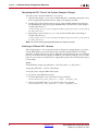
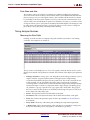
3.
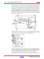
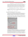
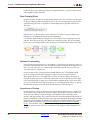
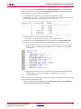
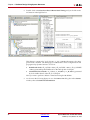
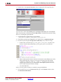
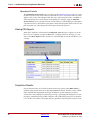
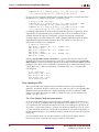
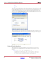
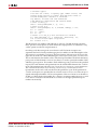
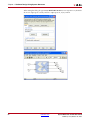
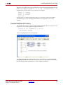
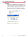
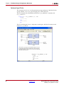
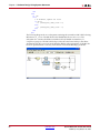
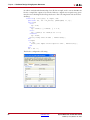
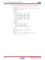
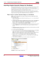
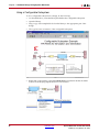
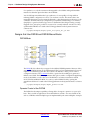
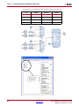
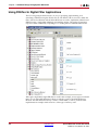
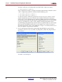
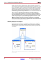
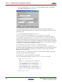
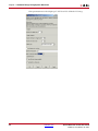
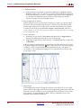
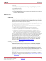
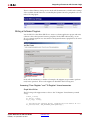
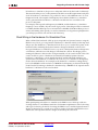
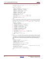
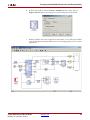
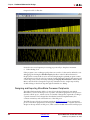
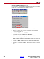
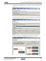
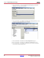
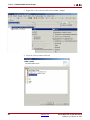
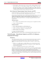
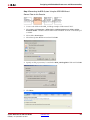
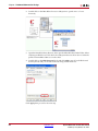
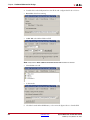
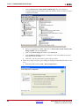
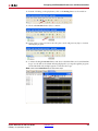
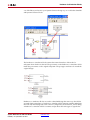
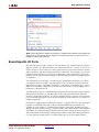
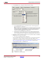
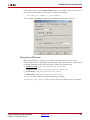
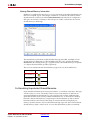
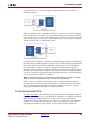
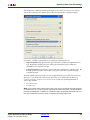
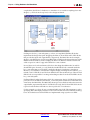
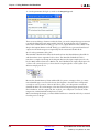
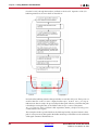
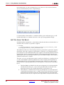
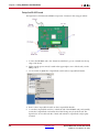
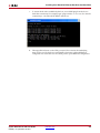
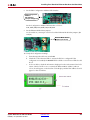
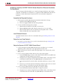
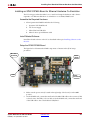
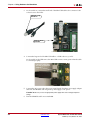
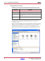
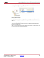
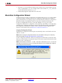
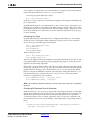
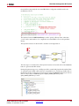
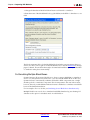
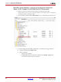
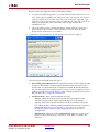
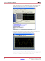
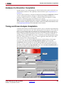
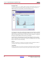
As shown below, Eject the CompactFlash card from the CompactFlash Reader.
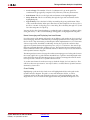
4.
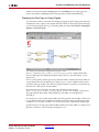
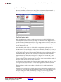
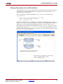
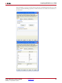
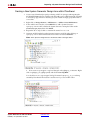
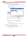
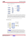
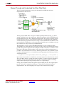
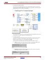
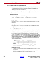
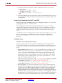
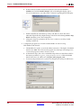
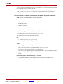
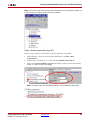
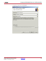
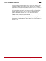
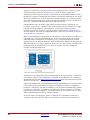
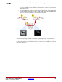
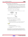
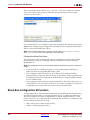
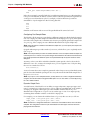
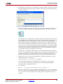
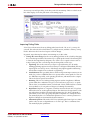
Remove the CompactFlash card from the CompactFlash Reader.
5.
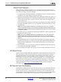
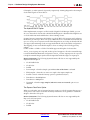
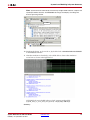
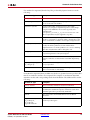
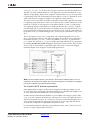
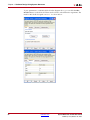
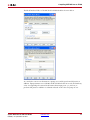
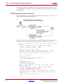
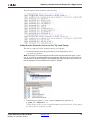
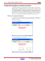
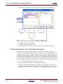
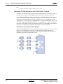
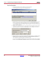
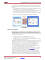
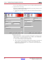
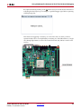
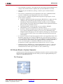
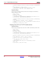
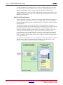
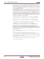
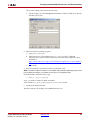
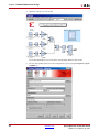
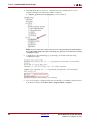
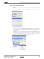
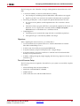
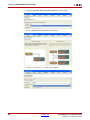
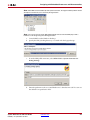
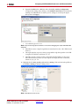
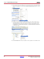
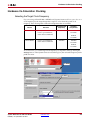
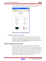
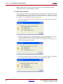
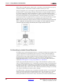
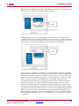
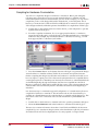
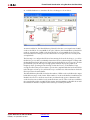
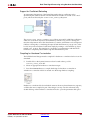
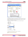
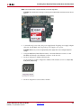
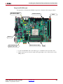
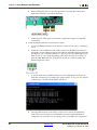
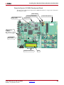
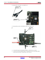
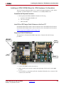
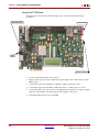
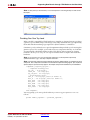
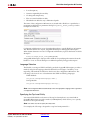
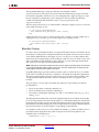
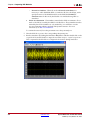
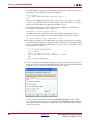
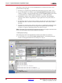
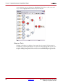
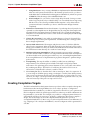
Locate the CompactFlash card slot (on the back side of the ML506 board), and carefully
insert the CompactFlash card with its front label facing away from the board. The
figure below shows the back side of the board with the CompactFlash card properly
inserted.
Note: The CompactFlash card provided with your board might differ.
Caution! Be careful when inserting or removing the CompactFlash card from the slot. Do not
force it.
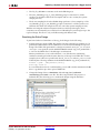
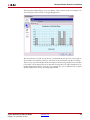
6.
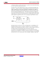
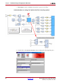
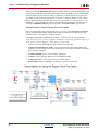
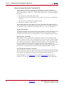
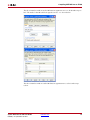
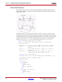
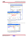
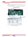
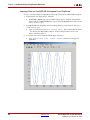
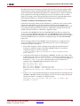
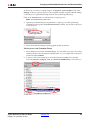
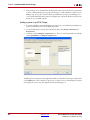
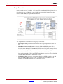
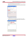
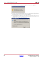
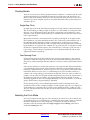
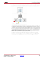
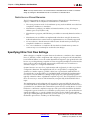
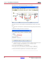
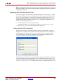
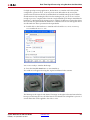
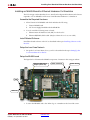
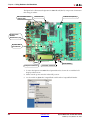
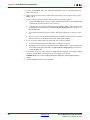
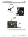
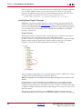
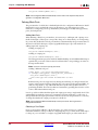
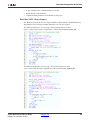
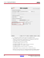
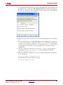
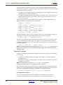
Connect the AC power cord to the power supply brick. Plug the 5V power supply
adapter cable into the ML506 board. Plug in the power supply to AC power.
Caution! Make sure you use an appropriate power supply with correct voltage and power
ratings.
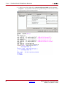
7.
302
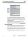
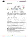
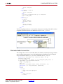
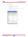
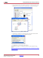
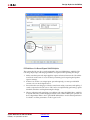
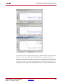
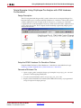
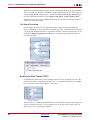
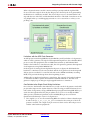
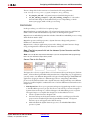
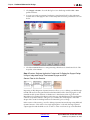
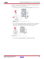
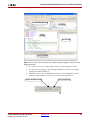
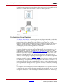
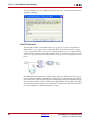
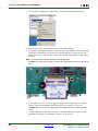
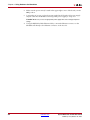
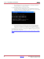
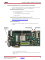
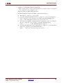
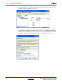
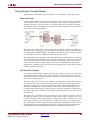
Using the RJ45 Male/Male Ethernet Cable, connect the Ethernet connector on the
ML506 board directly to the Ethernet connector on the host PC.
www.xilinx.com
System Generator for DSP User Guide
UG640 (v 14.3) October 16, 2012