1
Using ChipScope Pro Analyzer for Real-Time Hardware Debugging
Using ChipScope Pro Analyzer for Real-Time Hardware Debugging
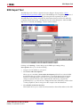
The integration of ChipScope™ Pro in the System Generator flow allows real-time
debugging at system speed. By inserting a ChipScope block into your System generator
design, you can debug and verify all the internal signals and nodes within your FPGA.
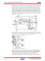
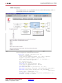
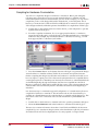
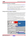
ChipScope Pro Overview
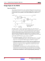
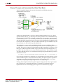
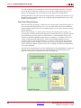
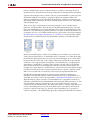
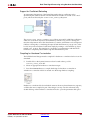
The increasing density of FPGA devices has rendered attaching test probes to these devices
impractical. The ChipScope™ Pro tools integrate key logic analyzer hardware components
with the target design inside of a Xilinx device. The ChipScope Pro tools communicate
with these components during system operation and in effect provide the designer with a
logic analyzer for nodes inside the Xilinx FPGA. ChipScope gives you a deep trace
memory, fast clock speeds and multiple trigger options, which can vary in complexity. You
can easily capture and view signal activity inside your FPGA without having to dedicate
critical logic space, come up with complex capture schemes, or allocate additional I/O
pins. Data samples are captured based on user-defined trigger conditions and stored in
internal block memory. All control and data transfer is done via the JTAG port eliminating
the need to drive data off-chip using I/O pins.
Please refer to the following Web page for further details on ChipScope Pro:
http://www.xilinx.com/ise/optional_prod/cspro.htm
Tutorial Example: Using ChipScope in System Generator
Note: This tutorial assumes that you have already installed and configured both the hardware and
software required to run an ML506 platform. For installation and configuration information, refer to the
ML506 documents located at the following web address:
http://www.xilinx.com/products/boards/ml506/docs.htm
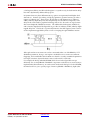
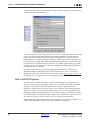
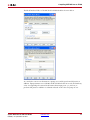
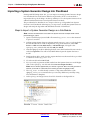
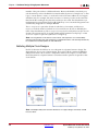
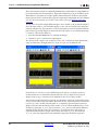
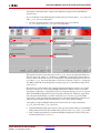
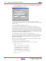
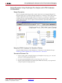
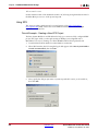
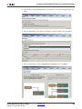
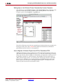
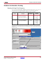
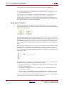
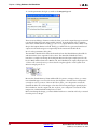
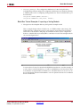
This tutorial shows how to modify a Simulink model to integrate the ChipScope™ block
and how to select the data to be captured and viewed for debugging. The steps are as
follows:
1.
2.
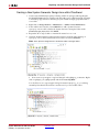
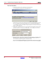
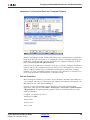
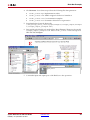
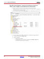
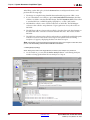
From the MATLAB console, change the directory to
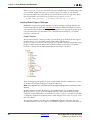
<sysgen_path>/examples/chipscope/example1. The following files are located in
this directory:
♦
chipscope_ex1.mdl – Your working model.
♦
chipscope_ex1_soln.mdl – Solution model, including the ChipScope block.
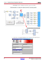
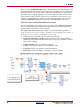
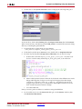
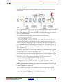
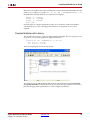
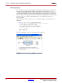
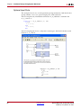
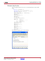
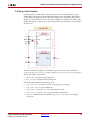
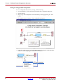
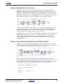
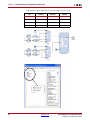
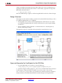
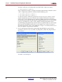
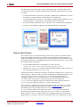
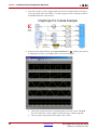
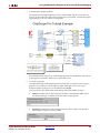
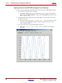
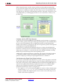
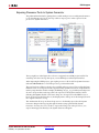
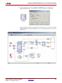
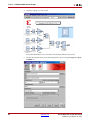
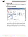
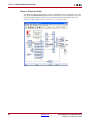
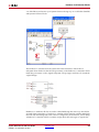
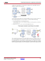
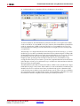
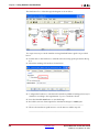
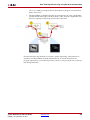
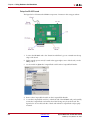
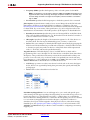
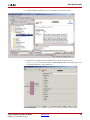
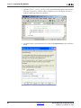
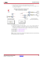
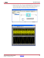
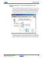
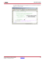
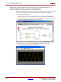
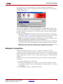
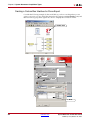
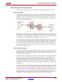
Open the chip_ex1.mdl model from the MATLAB console. This model represents a
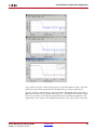
simple usage model of a DDS Compiler block that will produce sine and cosine output
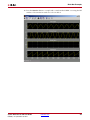
waveforms. Both sine and cosine output waveforms will later be connected to a
Chipscope block, enabling you to debug and verify the Systen Generator block by
probing and plotting the waveforms.
System Generator for DSP User Guide
UG640 (v 14.3) October 16, 2012
www.xilinx.com
139