1
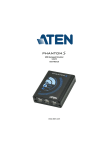
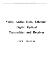
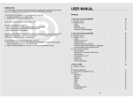
__________________________________________ PROFESSIONAL TIMING HL 2-32 PHOTOCELL USER’S MANUAL DESCRIPTION Version 1.3 TS Dec 08 The infra-red photocell HL 2-32 set is composed of two transmitters (HL 2-32E) and two receivers (HL 2-32R). There are 4 matched units in each set allowing system A and B coverage of a timing line. All units are internally battery powerered only (A-type x 3). Adjustment of the output impulse time (blocking after initial triggering) is available on the receivers. This photocell satisfys the most exacting requirements of sports timing and is normally used at finish lines where parallel redundancy of two sets of independent sensors is needed for A and B timing systems (as required for FIS ski events and equestrian jumping for example) The sets of photocells (4 units in all) are matched and tuned to work with eachother and should be kept as a set. Do not mix units with other sets since unwanted interfrerence from the two sources of coded transmitters may result. Any repairs and adjustements MUST be done as a matched set of 4 units. The theory of operation is to provide two sets of photocells that are fail-operational. Both transmitters (Tx) are placed on one side of the finish together, the two receivers (Rx) are likewise placed together on the opposite side from the receivers. The transmitters should ultimately be aimed to cover BOTH receivers at the same time. In this manner a failure or disalignment of one transmitter will still allow both receivers to operate normally. (We would further recommend the use of and optocoples system (the HL 533 FIS-type for example) to greater enhance the fail-operational nature of these products in an A/B timing system set-up) The transmitters emit a coded Irfrared (IR) signal controlled by individual timing oscillators in each Tx unit that are only recognized by the matched receivers. A syncronization cable to link the two Tx units’ oscillators is essential and must ALWAYS be installed for proper operation. The fact that there are two separate housings on each side of the finish line further increases the redundancy of this set-up and dsign. This OSC link cable keeps the Tx units working in harmony as they send the coded IR beams to the receivers. This makes sure that the coded infrared signals being sent to the to receivers do not interfere with eachother and cause false triggering. Without the OSC link syncronization cable on the Tx side the photocells will probably trigger incorrectly and will send random impulses. Syncronizing the IR signal source on the transmit side provides complete rejection of anything but the coded IR signal at the receiver end and the assurance that no interference from the two transmitters’ unsynchronized oscillators, or other IR sources (sunlight/flash), will cause the two receivers to trigger incorrectly. PHYSICAL SET-UP Transmitters are on one side, receivers are on the other. Do not set up in an opposite manner. We recommend the use of 4 separate support posts (one for each unit) so that a disturbance or problem with on post will not case a failure of the entire A/B concept. Units are placed in as close vertical proximity as possible. Do not separate vertically by more than 10cm as this may cause alignment, accuracy and triggering problems. The goal in set up is to make certain the physical set up allows BOTH transmitters to “cover” BOTH receivers. Only close vertical separation will allow this. DO NOT attmpt to isolate the two sets. The whole idea is to allow either/or of the transmistters to “cover” the two receivers on the opposite side. In such a set up the physical redundancy of the two receivers remains completely functional and accurate even if one of the transmistter should fail. Example: For all races regulated by the international Ski Federation (FIS) RECEIVERS TRANSMITTERS The cells work perfectly over a distance between transmitter and receiver of up to 40 m (130 ft.) in the "LOW" position. Working distances of up to 80 m and better (260 ft) is possible in the "HIGH" position. Always try to use the lowest possible power setting to effect proper alignment. Only use the “HIGH” transmitter settings when snow, dust or distance conditions require such power. It is possible to over-power the signal on HIGH when the set-up widths are 30m or less. Do not try to compensate for poor aiming by increasing the TX outputs unnecessarily. OPERATION INSTRUCTIONS Set-up and switch on ONE transmitter with ② in LOW mode. (Use HIGH only when necessary) Watch very carfully for BOTH the BATT and OSC (Oscillator Syncro Lock) LEDs to illuminate briefly and then immediately go out. This is the NORMAL start-up condition and it is important to see it happen this way. If the Transmitter OSC or BATT lights don’t flash momentarily at power-up or remain on (or flash) after power-up, remedial action is required (as described below). a) Battery check When you switch on the photocells (either the Tx or Rx units), the LED illuminate briefly and then immediately go out. This is normal. I New Batteries ③ Comes on briefly and then goes out. ③ "BATT" should II Used batteries ③ flashes slowly (once every 2 sec.). In this state you still have at least 30 hours of operation at 20° C. III Flat batteries ③ flashes rapidly (once every sec.). The batteries must be replaced. If this arises during timekeeping the batteries will ensure at least 6 hours of work at 20° C after the quick flashing starts. WARNING Battery (hours of use) is very much reduced below 0° C and depends on their quality. We strongly recommend to use new batteries as soon as LED ③ flashes. The use of Lithium batteries for colder temperatures is highly recommended and provides excellent value (operating time/cost) relative to alkaline options. b) OSC check - Transmitter Each transmitter has an OSC (Oscillator) LED condition light. This indicator must light-up very briefly when the Transmitter is first switched on, and then go out right away. If the OSC light stays on after power-up or comes on during operation, this indicates a problem (the oscillator that provides the coded IR signal did not start up and/or is not working correctly) This can normally be remedied by turning the transmitter off/on (slowly – wait 4 seconds in the off position before turning on) again, sometimes repeatedly. The OSC LED must be off after power-on or the cells are unuseable. c) Lining-up the photocells One transmitter should now be on and roughly aimed at the two receivers. Go over to the receiver side and switch on the two receivers with ②. When you switch on the receivers, the LED "SIGNAL" ④ illuminates as long as the transmitter(s) is/are not lined-up with the receiver(s). This “SIGNAL” LED on the receivers is linked to another red LED behind the lower lens on the other side of the housings that also shows you when the photocells “trigger” (flash of red) or are not lined-up (solid red). Using the sighting groove ① as a rough guide align the two receivers with the aim point of the transmitters’ supports on the other side of the line and ty to get an initial aim and ‘lock”. Watch the “SIGNAL” LED for a reaction one it starts to respond. As soon as the signal light starts responding to your aiming avoid using the sighing goove and watch the response of the red LED only for aiming. You want the red signal LED to extinguish and stay extinguished. Once the red signal LED stays solidly OFF, go back over and readjust the ONE transmitter on the other side of the line. Continue to refine the aim point for BOTH receivers by carefully adjusting the transmitter(s). Use the sighting groove ① as a rough guide. Make sure the transmitter is on and all LEDs are extinguished (normal). Try to get the one transmitter to aim at and “cover” both receivers and make the red “signal” lights on each receiver go out. You’re looking for a “center point” of best aim. Take your time and work back and forth if necessary using the two receivers and ONE transmitter at first. Fine-tune this alignment on LOW power until one transmitter is covering the TWO receivers perfectly. Go back to the receivers and aim them again by using the sighting groove ①. Once roughly aimed, carefully move each receiver to zero-in on the transmitter signal using the “SIGNAL” LED condition as your only guide. Once the “SIGNAL” LED starts responding to aiming, avoid using the housing as a rough guide and now use the SIGNAL LED reaction exclusively to fine-tune the aim point. You are in proper alignment when LED ④ "SIGNAL" is firmly and soldly off (not even flickering) and stays off even if you move the receiver photocell slightly (the “tap” test). Return to the transmit side and now finally fine-tune the aim of the transmitter to the receivers with the aid of the red LED as seen through the lower lens of the receiver. This luminous indicator placed under the receiving lens allows you to very accurately “center” the alignment of the transmitter on the receiver from across the line and is a huge assistance to assuring correct installation. It should be possible on low power at 40m to easily find the solid center-point of the aim of one transmitter to both receivers. Turn OFF the first transitter once aligned, and repeat the same process with the second transmitter. It is crucial that the two transmitters be able to independently cover BOTH receivers. Only when both transmitters are aimed, turn off BOTH transmitters and Install the transmitter Synchronization link cable into the SYNCRO jacks on each transmitter housing. Do not overtighten this cable connection. When the cable is installed, turn on the transmitters simultaneously and watch for all LED’s to flash and extinguish. Check alignment one last time by momentarily covering one of the two transmitters to see that no signal is produced on the receivers (watch the lower lens of the receivers for a red flash/light when triggered/obscured). We recommend that transmitters and receivers be steadily and solidly mounted on supports such as HL4-3, or on high quality tripods (not permitted for FIS skiing applications - solid surfaces only, not snow). If the support structures are not solid or straight the alignment and stability will be very difficult to achieve. This point cannot be understated and the quality of the support system will dramatically influence your success in aiming and keeping these cells properly aligned throurgout the competition. There should be absolutely no movement in the supports you chose or the brackets you work with. Go to the expected trigger point of the finish line and use your hand to find the exact trgger point of the receive cells. You can look at the lower lens of the receivers to see the red LED trigger. When you obstruct the beam between the transmitters and receivers, the LED "SIGNAL" ④ comes on momentarily and the timing impulse is provided at the output connections ⑦. This test at the resulting beam line will tell you if the beam is too high or low and EXACTLY where the trigger point is. Move the cells higher in snowy and dusty conditions but be aware that placing cells too high can cause athletes or vehicles to slip under the finish beams. Installation of the cells TOO HIGH is a VERY COMMON MISTAKE. Check the actual trigger point with your hand. d) Direct / Impulse (adjusting length of impulse) ⑥ Depending on the sport to be timed and the application, it may be necessary select either “direct” trigger output to the timer, or to have a period of time in which the photocells’ output pulse for timing is blocked (“Impulse”) between the impulse generated and the NEXT impulse sent. The most popular method is to use “Impulse” settings so that you can adjust (using the lower knob) the Impulse signal width from .01 seconds to 2.4 seconds. Direct” ties the output trigget “direct”ly to the photocell sensor. The impulse length is thus not adjustable and is always a function of how long the photocell signal is obstructed. This can be very useful for determining out-of-alingmnet status or how many objects pass in sequence in front of the cells. The “Impulse” settinmg is very useful in one-by-one sports (alpine skiing, Equestrian). This is in order to eliminate additional unwanted and unnecessary times caused by the moving body parts after intital triggering of the valid signal (you want to “lock-out” following impulses for a certain time once the front of the body is correctly detected). Alpine Skiing would use a low setting (3/100ths/sec or so). Cross Country or motorsports might select ½ sec. In all cases the “lock-out” time is set by the user based on conditions and preferences using the knob on the receiver housing to the times indicated on the dial. Avoid very long lock-out values so that times are not lost or swallowed-up if following athletes/vehicles are expected close together. Min. adjustment : Duration of impulse 1/100 sec. Max. adjustment : Duration of impulse 2.4 sec. Note: Older models of the HL 2-32 set do not have the “direct” option and only provide “Impulse” type operation via an ON/OFF switch in the same location e) Output jacks ⑦ Normally-Open collector outlet - working contact (short circuit between black and green terminals). Use only high-quality banana plugs. Green terminal : Impulse Black terminal : Ground When you initially connect to your timer, polarity of this two-wire connection is important (no damage will result – it just won’t trigger the connected timer). f) Changing the batteries Remove the screw underneath the case. Slide the electronic unit out of the case. Change the 3 batteries observing the polarities marked on the bottom. Be sure to use good quality Alkaline type 1.5 volt batteries (UCAR Energizer E-91). The use of high quality Lithium batteries is also recommended and yields weeks of constant use. Check the operation and roll the batteries in the casing to ensure proper seating. Put the electronic unit back in the case and replace the screw carefully (do not overtighten). HL 2-32 PHOTOCELL ① Sighting groove ② ON/OFF switch or Direct/OFF/Impulse (Receiver) ③ Battery check (Normally Off) ④ Alignment check LED (Off = Aligned) ⑤ OSC * SYNCHRO Cable Jack ⑥ Impulse length adjustment ⑦ Output jacks ⑧ Serial number (keep matched sets together) ⑨ Oscillator Status Indicator (normally off) * The “SYNCHRO” plug alows for using 2 photocells in parallel. TECHNICAL SPECIFICATIONS Principle High frequency infra-red (50 KHz) Detection of signal by frequency discrimination (code) Distance for use 40 + Meters in "LOW" position 80 + Meters in "HIGH" position Output impulse adjustable By optocouplers and working contact. Impulse from 1/100 sec. to 2 seconds Working temperature - 20°C to + 50°C (Tested actual to - 38°C) Internal power 2 x 3 batteries 1.5 V "Alkaline" Type AA or UM – 3 Lithium preferred in cold temps. Power reserve in "LOW" pos. 100 hours at 20°C 50 hours at -20°C Power reserve in "HIGH" pos. 50 hours at 20°C 20 hours at -20°C LED Checks - State of batteries - Alignment - Code Oscillator Status Precision of repetive impulsions +/- 0.02 ms Dimensions 2 cases of 150 x 80 x 40 mm (6x3,1x1,5 inches) Weight (incl. batteries ) 800 gr (29 ounces) transmitter + receiver Mounting with supports ref. HL4-3 or tripods (1/4 " camera thread) Maintenance Although this photocell is built to work in hard conditions, we advise you to sometimes open the aluminium cover and to let it dry when the photocell has been exposed to humidity. TAG Heuer PROFESSIONAL TIMING 14 a, Avenue des Champs Montants CH-2074 Marin Tél. 032 / 755 60 00 Fax 032 / 755 66 82 E-mail: [email protected] http://www.tagheuer-timing.com