1
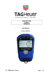
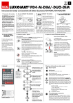
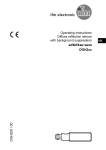
HL2-33 PHOTOCELL USER MANUAL Version 11/2013 TAGHeuer Timing Page 1 / 12 DESCRIPTION The Infra-Red photocell HL2-33 set is composed of two transmitters (HL2-33E) and two receivers (HL2-33R). There are 4 matched units in each set allowing system A and B coverage of a timing line. All units are internally battery powered only (2x 3 AA-type per unit). Adjustment of the output impulse time (blocking after initial triggering) is available on the receivers. This photocell satisfies the most exacting requirements of sports timing and is normally used at finish lines where parallel redundancy of two sets of independent sensors is needed for A and B timing systems. The sets of photocells (4 units in all) are matched and tuned to work with each other and should be kept as a set. Do not mix units with other sets since unwanted interference from the two sources of coded transmitters may result. Any repairs and adjustments MUST be done as a matched set of 4 units. The theory of operation is to provide two sets of photocells that are fail-operational. Both transmitters (Tx) are placed on one side of the finish together, the receivers (Rx) are likewise placed together on the opposite side from the transceiver. The transmitters should ultimately be aimed to cover BOTH receivers at the same time. In this manner a failure or misalignment of one transmitter will still allow both receivers to operate normally. We would further recommend the use of an optocopler system (the HL 533) to greater enhance the fail-operational nature of these products in an A/B timing system set-up) The transmitters emit a coded Infrared (IR) signal controlled by individual timing oscillators in each Tx unit that are only recognized by the matched receivers. A synchronization cable to link the two Tx units’ oscillators is essential and must ALWAYS be installed for proper operation. The fact that there are two separate housings on each side of the finish line further increases the redundancy of this setup and design. This OSC link cable keeps the Tx units working in harmony as they send the coded IR beams to the receivers. This makes sure that the coded infrared signals being sent to the two receivers do not interfere with each other and cause false triggering. Without the OSC link synchronization cable on the Tx side the photocells will probably trigger incorrectly and will send random impulses. Synchronizing the IR signal source on the transmit side provides complete rejection of anything but the coded IR signal at the receiver end and the assurance that no interference from the two transmitters’ unsynchronized oscillators, or other IR sources (sunlight/flash), will cause the two receivers to trigger incorrectly. TAGHeuer Timing Page 2 / 12 PRINCIPAL The above photocell works perfectly with a distance between transmitter and receiver of up to 40 m. (130 ft.) in "LOW" position and up to 80 m (260 ft) in "HIGH" position. PHYSICAL SET-UP Transmitters are on one side, receivers are on the other. Do not set up in an opposite manner. We recommend the use of 4 separate support posts (one for each unit) so that a disturbance or problem with on post will not case a failure of the entire A/B concept. DO NOT attempt to isolate the two sets. The whole idea is to allow either/or of the transmitters to “cover” the two receivers on the opposite side. In such a set up the physical redundancy of the two receivers remains completely functional and accurate even if one of the transmitters should fail. RECOMMENDED USE The photocells must be placed within close vertical proximity to each other when used at the same timing line in order to avoid large differences in triggering times. For added timing system dependability, use these photocells with our HL 553 impulse distributor and optocoupler When the photocells are mounted, connect both transmitters with the dedicated cable on the SYNCHRO (3 pins plug). To line up correctly these double photocells, line up first the upper transmitter with the upper receiver. The bottom photocells are OFF. When the alignment is correct, turns OFF the upper photocells and ON the bottom one and line up them correctly. Then, switch ON again the upper photocells and test them masking one of the transmitter and after the other one. TAGHeuer Timing Page 3 / 12 OPERATION INSTRUCTIONS Set-up and switch on ONE transmitter with (10) in LOW mode. (Use HIGH only when necessary) Switch on the photocells (2) on “IMPULSE” mode (standard use) or “DIRECT” mode Depending on the sport to be timed and the application, it may be necessary select either “direct” trigger output to the timer, or to have a period of time in which the photocells’ output pulse for timing is blocked (“Impulse”) between the impulse generated and the NEXT impulse sent. The most popular method is to use “Impulse” settings so that you can adjust (using the lower knob) the Impulse signal width from 0.01 seconds to 2.4 seconds. “Direct” ties the output trigger “directly to the photocell sensor. The impulse length is thus not adjustable and is always a function of how long the photocell signal is obstructed. This can be very useful for determining out-of-alignment status or how many objects pass in sequence in front of the cells. Watch very carefully for BOTH the BATT and OSC (Oscillator Syncro Lock) LEDs to illuminate briefly and then immediately go out. This is the NORMAL start-up condition and it is important to see it happen this way. If the Transmitter OSC or BATT lights don’t flash momentarily at power-up or remain on (or flash) after power-up, remedial action is required (as described below). A) Battery Check When you switch on the photocell, the LED (3) "BATT" illuminates briefly and goes out. I New Batteries (3) does not illuminate II Used batteries (3) flashes slowly (once every 2 sec.). The batteries insure at least 30 hours of functioning at 20° C III Flat batteries TAGHeuer Timing (3) flashes rapidly (once every sec.). The batteries must be replaced. If this arises during the timekeeping the batteries will insure at least 6 hours of functioning at 20° C. Page 4 / 12 WARNING Battery (hours of use) is very much reduced below 0°C (32°F) and depends on their quality. We strongly recommend using new batteries as soon as LED (3) flashes. The use of Lithium batteries for colder temperatures is highly recommended and provides excellent value (operating time/cost) relative to alkaline options Do not use rechargeable batteries. B) OSC Check – Transmitter Each transmitter has an OSC (Oscillator) LED condition light. This indicator must light-up very briefly when the Transmitter is first switched on, and then go out right away. If the OSC light stays on after power-up or comes on during operation, this indicates a problem (the oscillator that provides the coded IR signal did not start up and/or is not working correctly) This can normally be remedied by turning the transmitter off/on (slowly – wait 4 seconds in the off position before turning on) again, sometimes repeatedly. The OSC LED must be off after power-on or the cells are unusable C) Lining up the photocells One transmitter should now be on and roughly aimed at the two receivers. Go over to the receiver side and switch on the two receivers with (2) and (10). When you switch on the receivers, the LED "SIGNAL" (4) illuminates as long as the transmitter(s) is/are not lined-up with the receiver(s). This “SIGNAL” LED on the receivers is linked to another red LED behind the lower lens on the other side of the housings that also shows you when the photocells “trigger” (flash of red) or are not lined-up (solid red). Using the sighting groove (1) as a rough guide align the two receivers with the aim point of the transmitters’ supports on the other side of the line and try to get an initial aim and ‘lock”. Watch the “SIGNAL” LED for a reaction one it starts to respond. As soon as the signal light starts responding to your aiming avoid using the sighting groove and watch the response of the red LED only for aiming. You want the red signal LED to extinguish and stay extinguished. Once the red signal LED stays solidly OFF, go back over and readjust the ONE transmitter on the other side of the line. Continue to refine the aim point for BOTH receivers by carefully adjusting the transmitter(s). Use the sighting groove (1) as a rough guide. Make sure the transmitter is on and all LEDs are extinguished (normal). Try to get the one transmitter to aim at and “cover” both receivers and make the red “signal” lights on each receiver go TAGHeuer Timing Page 5 / 12 out. You’re looking for a “center point” of best aim. Take your time and work back and forth if necessary using the two receivers and ONE transmitter at first. Fine-tune this alignment on LOW power until one transmitter is covering the TWO receivers perfectly. Go back to the receivers and aim them again by using the sighting groove (1). Once roughly aimed, carefully move each receiver to zero-in on the transmitter signal using the “SIGNAL” LED condition as your only guide. Once the “SIGNAL” LED starts responding to aiming, avoid using the housing as a rough guide and now use the SIGNAL LED reaction exclusively to fine-tune the aim point. You are in proper alignment when LED (4) "SIGNAL" is firmly and solidly off (not even flickering) and stays off even if you move the receiver photocell slightly (the “tap” test). Return to the transmit side and now finally fine-tune the aim of the transmitter to the receivers with the aid of the red LED as seen through the lower lens of the receiver. This luminous indicator placed under the receiving lens allows you to very accurately “center” the alignment of the transmitter on the receiver from across the line and is a huge assistance to assuring correct installation. It should be possible on low power at 40m to easily find the solid centre-point of the aim of one transmitter to both receivers. Turn OFF the first transmitter once aligned, and repeat the same process with the second transmitter. It is crucial that the two transmitters be able to independently cover BOTH receivers. Only when both transmitters are aimed, turn off BOTH transmitters and Install the transmitter Synchronization link cable into the SYNCRO jacks on each transmitter housing. Do not overtighten this cable connection. When the cable is installed, turn on the transmitters simultaneously and watch for all LED’s to flash and extinguish. Check alignment one last time by momentarily covering one of the two transmitters to see that no signal is produced on the receivers (watch the lower lens of the receivers for a red flash/light when triggered/obscured). We recommend that transmitters and receivers be steadily and solidly mounted on supports such as HL4-3, or on high quality tripods (not permitted for FIS skiing applications - solid surfaces only, not snow). If the support structures are not solid or straight the alignment and stability will be very difficult to achieve. This point cannot be understated and the quality of the support system will dramatically influence your success in aiming and keeping these cells properly aligned throughout the competition. There should be absolutely no movement in the supports you chose or the brackets you work with. TAGHeuer Timing Page 6 / 12 Go to the expected trigger point of the finish line and use your hand to find the exact trigger point of the receive cells. You can look at the lower lens of the receivers to see the red LED trigger. When you obstruct the beam between the transmitters and receivers, the LED "SIGNAL" (4) comes on momentarily and the timing impulse is provided at the output connections (7). This test at the resulting beam line will tell you if the beam is too high or low and EXACTLY where the trigger point is. Move the cells higher in snowy and dusty conditions but be aware that placing cells too high can cause athletes or vehicles to slip under the finish beams. Installation of the cells TOO HIGH is a VERY COMMON MISTAKE. Check the actual trigger point with your hand. D) Delay (Adjusting length of impulse) (6) The “Impulse” setting is very useful in one-by-one sports (alpine skiing, Equestrian). This is in order to eliminate additional unwanted and unnecessary times caused by the moving body parts after initial triggering of the valid signal (you want to “lock-out” following impulses for a certain time once the front of the body is correctly detected). Alpine Skiing would use a low setting (3/100ths/sec or so). Cross Country or motorsports might select ½ sec. In all cases the “lock-out” time is set by the user based on conditions and preferences using the knob on the receiver housing to the times indicated on the dial. Avoid very long lock-out values so that times are not lost or swallowed-up if following athletes/vehicles are expected close together. Min. adjustment : Duration of impulse 1/100 sec. Max. adjustment : Duration of impulse 2.4 sec. Note: Older models of the HL 2-32 set do not have the “direct” option and only provide “Impulse” type operation via an ON/OFF switch in the same location TAGHeuer Timing Page 7 / 12 E) Output jacks (7) Normally-Open collector outlet Working contact (short circuit between black and green terminals Use only high-quality banana plugs Green terminal : Impulse Black terminal : Ground When you initially connect to your timer, polarity of this two-wire connection is important (no damage will result – it just won’t trigger the connected timer). F) Changing the batteries Remove the screw underneath the case. Slide the electronic unit out of the case. Change the 3 batteries observing the polarities marked on the bottom. Be sure to use good quality Alcaline type 1.5 volt batteries (UCAR Energizer E-91). Put the electronic unit back in the case and do up the screw carefully. DO NOT OVERTIGHTEN. The use of high quality Lithium batteries is also recommended and yields weeks of constant use. Check the operation and roll the batteries in the casing to ensure proper seating. IMPORTANT If timing is interrupted for a long period or when it is finished: Turn button (2) and (10) TO OFF position PHOTOCELL HL 2-33 TAGHeuer Timing Page 8 / 12 1 4 3 1) Sighting groove 2) Direct / OFF / Impulse switch 3) Battery Check (Normally Off) 4) Alignement Check led (Off = Aligned) 5) OSC* Synchro Cable Jack 6) Locking Impulse adjustment 7) Output jacks 8) Serial Number (keep matched sets together) 9) Oscillator Status Indicator (Normally Off) 10) Low / OFF / High Switch 2 3 4 6 7 9 10 5 3 * * The “SYNCHRO” plug allows for using 2 photocells in parallel. 2 1 TAGHeuer Timing 2 3 1 3 Page 9 / 12 TECHNICAL SPECIFICATIONS Principle High frequency infra-red (50 KHz) Detection of signal by frequency discrimination Distance for use 40 Meters (131 ft.) in "LOW" position 80 Meters (262 ft.) in "HIGH" position Output impulse adjustable By optocouplers and working contact. Impulse from 1/100 sec. to 2 seconds Working temperature - 20°C to + 50°C (-4°F to 122°F) External power supply 6 – 12V DC, max. current 100 mA Internal power 2 x 3 batteries 1.5 V "Alkaline" Type AA Energizer LR6 Power reserve in "LOW" pos. 100 hours at 20°C (68°F) 50 hours at -20°C (-4°F) Power reserve in "HIGH" pos. 50 hours at 20°C (68°F) 20 hours at -20°C (-4°F) LED Checks - State of batteries - Alignment - Code Oscillator Status Precision of repetitive impulsions +/- 0.02 ms Dimensions 2 cases of 160 x 160 x 40 mm (6 x 6 x 1,5 inches) Weight (incl. batteries) 800 gr (29 ounces) transmitter / receiver Mounting with supports ref. HL4-3 or tripods (1/4 " camera thread) TAGHeuer Timing Page 10 / 12 Maintenance Although this photocell is built to work in hard conditions, we advise you to open sometimes the aluminium cover and to let it dry when the photocell has been exposed to humidity. Special Note In case you use an external power supply, we advise you to place, in any case, 3 internal batteries. These will insure the functioning of the photocell in case of current cut off or falling voltage. TAGHeuer Timing Page 11 / 12 TAG Heuer PROFESSIONAL TIMING 6A Louis-Joseph Chevrolet 2300 la Chaux-de-Fonds Switzerland Tel : 032 919 8000 Fax : 032 919 9026 E-mail: [email protected] Http: //www.tagheuer-timing.com TAGHeuer Timing Page 12 / 12