1
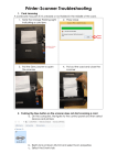
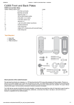
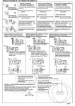
Packing Contents
ⒶOutside Handle Set
(Including outside setting plate)
ⒷInside Handle Set
ⒸInside setting plate
ⒼStrike & Dust Box
ⒻAccessory
1 Screw (lockcase and strike)
○
52-EC300-03
BAP058
ⒹLock case
ⒺCylinder & Key
ⒽRFID card
I Instruction
○
4pcs
Setting
2 Spindle
○
1pcs
3 Trim Screws
○
3pcs
4 Hex Key
○
1pcs
5 Support Nut Screws
○
2pcs
PS. : Janus TN without
6 Support Nut
○
2pcs
setting card.
card
Installation Steps 2-1
2 go through lockcase
1. According to template and have holes ready 2.1. Take off the face plate and save it for step9。 3.1 .Have leaver spindle○
from inside of door until its bulge hits
for installation. Make sure the lockcase type 2.2. Place lockcase in place and make sure the
lockcase .
deadbolt is retracted. Fixing the lockcase by
is consistent with door direction (right or left
3.2 .The ditch on the spindle is for fixing the lever
1 .
screwing two screws○
hands).
hex screws; therefore, find out the position
of the hex screws on the lever and have the
ditch toward it. (may vary from different
models)
Outside
Insid
Short
bulge
Long
6 on outside handle set○
A and make sure the square hole is
4.1.Tighten support nut○
upright.
4.2.Place outside handle set from outside of door and well place the wire through
the hole. Again, make sure the bulge on lever spindle hits lockcase and two
support nuts must go into lockcase .
Outside
5. Install cylinder clockwise and tighten the cylinder screws on
the side. Checking function by turning the key back and
force.
Inside
wire
Tighten
Cylinder
Tighten
support nut○
6
Make sure square
hole is upright
52-EC300-03
BAP058
Screws
6. Install inside setting plateⒸ by screwing
5 . Make sure the inside
support nut screws○
setting plate is placed upright.
Outside
Installation Steps 2-2
B from inside. Place
7.1.Install inside handle set○
spindle and connect wire in right place.
7.2.Make sure the turn piece is in its horizontal
position.
3 .
7.3.Tighten 3 trim screws○
8.1.Install battery and refer to user manual for
setting. The valid electronic keys can open
the door from outside by operating the
outside lever to retract latch.
8.2 Operating inside lever and make sure it will
retract both deadbolt and latch.
Note: Make sure the turn piece is in its
horizontal position when deadbolt is retracted.
10.Make sure step 7.3 and 8 is completed and
4 to tighten hex screws on
use Hex key○
both leavers.
Note: To avoid spindle is loosen and
unscrewed hex screws may cause safety
risk when operating, please make sure the
lever hex screws are well tighten
Note: Strike & dust boxⒼ are used on door
frame. Both outside and inside leaver
sets should be cleaned up by soft and dry
cloth to keep it shining. It is strictly
forbidden to use organic solution and
corrosive chemicals on the surface.
Inside
9.1.For automatic deadbolt: Press auxiliary latch
for deadbolt to be projected. Place faceplate
and screws back from step 2.1.
9.2.For non-automatic deadbolt: Turning turn
piece to be vertical for deadbolt to be
extracted. Place faceplate and screws back
from step 2.1.
Outside
Outside
Inside
hex screws
52-EC300-03
BAP058
Inside