1
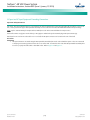
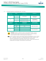
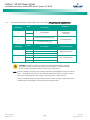
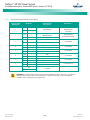
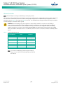
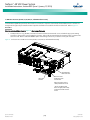
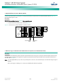
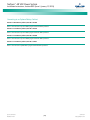
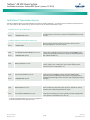
NetSure™ -48 VDC Power System
Installation Instructions, Section 6031 (Issue S, January 12, 2015)
Table 8.
Status and Alarm Indicators
Component
Rectifier
Modules
ACU+
Indicator
Normal State
Power
(Green)
On
Protection
(Yellow)
Off
Alarm
(Red)
Off
Status
(Green)
On
Minor
(Yellow)
Off
Critical or Major
Alarm
(Red)
Off
CONFIGURING THE ACU+ IDENTIFICATION OF RECTIFIERS AND
ASSIGNING WHICH INPUT PHASE IS CONNECTED TO EACH
RECTIFIER
If a password screen opens, a password must be entered
to allow the User to make adjustments. If a password was
previously entered and has not yet timed out, skip this
step and proceed to step 3). Otherwise, to enter a
password, with the cursor at the User Name field (default
is “Admin”), press the down arrow key to move cursor
down to the password line. Press ENT. “0” is highlighted.
Press the up arrow key once to change the “0” to”1”
(default password is “1”), then press ENT twice. (Note: If
you have been assigned a unique User Name and
password, follow this procedure to enter these.)
3.
6.
If you wish to change the Rectifier Phase Assignment,
navigate to and select “Rect Phase”. Press ENT. Use the
up or down keys to change the phase connected to the
flashing rectifier. Press ENT.
7.
Press ESC to return to rectifier menu screen.
8.
Navigate to and select the next rectifier.
9.
Repeat steps 4) through 8) for each of the remaining
rectifiers in the system.
13. Press ENT to select the operation. Press ENT again to
confirm.
Note: Check you numbering to be sure it is correct. If there
where conflicts in your numbering, rectifiers with conflicts
will be assigned the next available sequential number.
14. Return to the Main screen by repeatedly pressing ESC
(escape).
ACU+ ALARM RELAY CHECK
The following procedures can be used to verify operation of the
external alarm relays in a Power System equipped with an ACU+
with the factory default configuration. Note that alarm relays on
an ACU+ with a custom configuration may operate differently.
Note: There are two methods to check alarm relays. The first is by
actually causing an alarm. The second is by using the ACU+
alarm relay check function. The first method is used in the
following procedures. Refer to the ACU+ User Instructions
(UM1M820BNA) for instructions using the ACU+ alarm relay
check function.
With the Settings menu screen displayed, navigate to
and select “Rectifier” (ENT).
Spec. No: 582136600
Model No: 211NGFB
If you wish to change the Rectifier IDs, navigate to and
select “Rectifier ID”. Press ENT. Use the up or down keys
to change the ACU+ identification number for the
flashing rectifier. Press ENT.
12. Navigate to “Confirm ID/PH”. Press ENT. “Yes”
highlights.
Procedure
2.
5.
11. Navigate to and select “Manual” (ENT) / “Rectifier” (ENT)
/ “All Rect Ctrl” (ENT).
Upon power up, the ACU+ arbitrarily assigns Phase A, B, or C to
each rectifier. This assignment is used to display rectifier AC input
phase voltage(s). The User may reassign the phase to each
rectifier per your specific installation by following the procedure
below. (Note: This power system is single phase only.)
With the Main screen displayed, press ENT to go to the
Main Menu. Navigate to and select “Settings” (ENT).
Navigate to “Rect #” (# is used here to represent the
rectifier identification number). Press ENT. The rectifier
# menu screen is displayed, and the green LED on one
rectifier starts flashing. This is the rectifier currently
identified by the ACU+ as rectifier #. (If this is not the
rectifier you want, press ESC to return to rectifier menu
screen and select a different rectifier.)
10. When you have finished selecting identification numbers
for all rectifiers, repeatedly press ESC to return to the
Main Menu.
When rectifiers are all installed prior to applying power and
starting the system, the order in which the ACU+ identifies the
rectifiers is by serial number (lowest serial number is Rect 1, next
lowest is Rect 2, etc.). If you prefer the ACU+ to identify the
rectifiers by position in the system, perform the following
procedure.
1.
4.
[60]
Section 6031
Issue S, January 12, 2015