1
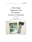
User’s Guide
Diagnostic Card
Laptop Dual
Version 1.0
User’s Guide
Model: dual_10
For use only in a laptop model computer with mini-PCI slot or
LPT (printer port) connection. (Device must be powered by USB).
1
User’s Guide
INTRODUCTION
The Dual Notebook Diagnostic Card is a powerful diagnostic tool for technicians and
administrators to troubleshoot various problems of notebook PC PII/III/ P4 by using a mini-PCI
and LPT (printer port) Bus. It is easy to install, yet extremely powerful to use. With this card in
hand, you no longer have to go through tedious and time consuming process of trying to figure out
what is wrong with your hardware. Notebook Diagnostic Card will indicate exactly what is wrong
with your notebook in just seconds. It saves your time and money.
Our new and improved design of Diagnostic Card, it can work with almost all popular types of
CPUs, Motherboards, and BIOS.
All though we try, it is not possible to update this manual every time a new motherboard is made by
the manufactures. It is always advised to visit the bios manufacture website, and download the
latest codes per bios revision. Or visit bioscentral.com for an online reference.
System Requirements
The Dual Notebook Diagnostic Card itself only requires an empty mini-PCI slot or LPT port
connection. It is not necessary to install memory chips to perform analysis. “POST Codes” can be
displayed through the hexadecimal display panel.
Tech Support
z
Tech Support
[email protected]
Dual Notebook Diagnostic Card INDICATORS
‘Indicators’ are any light emitting diodes (LED) or hexadecimal display panel is mounted on
extended cable. This section discusses the following indicators that appear on the Notebook
Diagnostic Card:
z
Dual Notebook mini-PCI & LPT Printer Port Bus Card
POST Code Display
The POST Code Display is made up of a dual, dot matrix hexadecimal read-out that displays Power
On Self Test (POST) status codes.
2
User’s Guide
Power On Self-Test (POST) Codes
This card can test the AMI/AWARD/PHOENIX BIOS, while it can be used in widely model of
notebook. During system booting up, this card displays can show the post codes. Refer to Appendix
A, it shows almost POST codes provided by BIOS manufacturers.
PCI Signal Definition:
CLK
+3.3
Motherboard Clock Signal. Should be on when power is supplied to the
motherboard even without CPU.
Motherboard Clock Signal. Should be on when power 3.3V is supplied to
the motherboard even without CPU.
INSTALLING Dual Notebook Diagnostic Card
Installation Procedure
TO INSTALL A Diagnostic Card:
1) Install the Notebook Diagnostic Card in mini-PCI slot or LPT Printer Port
2) Power on the machine and monitor the code shown on LED
3) When using the LPT printer mode, USB cable must be used to supply power to PC Diagnostic
card. USB cable not required when using mini-PCI slot mode.
3
User’s Guide
POST Codes
When the machine is turned on, the hexadecimal display should show the various POST codes
(Post 80H + 84H) as the system executes (unless it has a rare BIOS that does not display POST
codes).
If the machine does not boot, system POST has detected a fatal fault and stopped. The number
showing in the hexadecimal display on the Notebook Diagnostic Card is the number of the test in
which POST failed. Refer to Appendix A for a listing of POST codes.
Troubleshooting During POST
After initial power up, Power-On Self-Test (POST) codes begin displaying on the Notebook
Diagnostic Card’s hexadecimal displays (for most machines).
NOTE: A few machines use the parallel port to display POST codes instead of the Diagnostic
Card.
THE POST PROCESS
The ROM built onto the motherboard of the computer rums its built-in POST (Power-On Self-Test)
when you switch power on to the computer, press the reset button on the computer, or press
Ctrl-Alt-Del (warm boot). POST performs a tightly interwoven initialization and testing process for
each of these methods, but it typically does not test or initialize memory above 64K for warm boot.
You can get an even better idea of the detailed process by studying the POST code listings in
Appendix A.
4
Appendix A
Error Code
Award (Edition: ELITEBIOS 4.51PG)
C0
Turn Off Chipset Cache
01
Processor Test 1
02
Processor Test 2
03
Initialize Chips
04
Test Memory Refresh Toggle
05
Blank video,Initialize keyboard
06
Reserved
07
Test CMOS Interface and Battery Status
BE
Chipset Default Initialization
C1
Memory Presence test
C5
Early Shadow
C6
Cache Presence test
08
Setup low memory
09
Early Cache Initialization
0A
Setup Interrupt Vector Table
0B
Test CMOS RAM Checksum
0C
Initialize Keyboard
0D
Initialize Video Interface
0E
Test Video Memory
0F
Test DMA Controller 0
10
Test DMA Controller 1
11
Test DMA Page Registers
12~13
Reserved
14
Test Timer Counter 2
15
Test 8259-1 Mask Bits
16
Test 8259-2 Mask Bits
17
Test Stuck 8259’s interrupt bits
18
Test 8259 Interrupt Functionality
19
Test stuck NMI Bits Parity/IO check
1A
Display CPU Clock
1B-1E
Reserved
1F
Set EISA Mode
20
Enable Slot 0
21-2F
Enable Slots 1-15
30
31
Size Base and Extended Memory
Test Base and Extended Memory
32
Test EISA Extended Memory
33-3B
Reserved
3C
Setup Enabled
5
Appendix A
3D
Initialize &Install Mouse
3E
3F
Setup Cache Controller
BF
Reserved
Chipset Initialization
40
Display virus protect disable or enable
41
Initialize Floppy Drive & Controller
42
Initialize Hard Drive &Controller
43
Detect & Initialize Serial/Parallel Ports
44
45
Reserved
Detect & Initialize Math Coprocessor
46
Reserved
47
Reserved
48-4D
Reserved
4E
Manufacturing POST loop or display message
4F
50
Security Check
Write CMOS
51
Pre-boot Enable
52
Initialize Option ROMs
53
Initialize Time Value
60
61
Setup Virus Protect
Set Boot Speed
62
Setup Numlock
63
Boot Attempt
BO
Spurious
B1
Unclaimed NMI
E1-EF
Bios Setup Page
FF
BOOT UP
Error Code
D0
AMIBIOS Edition ( 071596)
NMI is Disabled.CPU ID saved. Init code Checksum verification starting
D1
D3
To do DMA init ,Keyboard controller BAT test ,start memory refresh and going
to 4GB flat mode
To start Memory sizing
D4
To comeback to real mode . Execute OEM patch. Set stack
D5
E000 ROM enabled . Init code is copied to segment 0 and control to be transferred
to segment 0.
Control point is in segment 0.To check <CTRL><HOME> key and verify main
BIOS
Checksum. If either<CTRL><HOME>is pressed or main BIOS checksum is bad
Go to check point E0 else goto check point D7
To pass control point to Interface Module.
D6
D7
D8
D9
Main BIOS runtime code is to be decompressed.
Control to be passed to main BIOS in shadow RAM
6
Appendix A
E0
On Board Floppy Controller (if any)is initialized. To start base 512K memory test
E1
To initialize interrupt vector table
E2
To initialize DMA and interrupt controllers
E6
ED
To enable floppy and timer IRQ,enable internal cache
Initialize floppy drive.
EE
Start looking for a diskette in drive A: and read 1st sector of the diskette
EF
Floppy read error
F0
Start searching ‘MIBOOT.ROM’ file in root directory
F1
‘AMIBOOT.ROM’ file not present in root directory.
F2
F3
Start reading FAT table and analyze FAT to find the clusters occupied by
‘AMIBOOT.ROM’ file
Start reading ‘MIBOOT.ROM’file cluster by cluster.
F4
AMIBOOT.ROM’ file not of proper size
F5
Disable internal cache
FB
Detect Flash type present.
FC
Erase Flash
FD
Program Flash
FF
Flash program successful.BIOS is going to restart
In F000 Memory Address for a real time code
03
NMI is Disabled . To check soft reset /power-on
05
BIOS stack set . Going to disable Cache if any.
06
POST code to be uncompressed.
07
CPU init and CPU data area init to be done.
08
CMOS checksum calculation to be done next.
0B
Any initialization before keyboard BAT to be done next
0C
KB controller I/B free. To issue the BAT command to keyboard controller.
0E
Any initialization after KB controller BAT to be done next.
0F
Key board command byte to be written.
10
Going to issue Pin-23,24 blocking/unblocking command.
11
Going to check pressing of <INS>,<END> key during power-on
12
13
To init CMOS if “Init CMOS in every boot ” is set or <END> key is pressed.
Going to disable DMA and Interrupt controllers
Video display is disabled port-B is initialized. Chipset init about to begin
14
8254 timer test about to start
19
About to start memory refresh test
1A
Memory Refresh line is toggling .Going to check 15us ON/OFF time
23
To read 8042 input and disable Megakey Green PC feature .Make BIOS segment
able to write
To do any setup before Int vector init
24
7
Appendix A
25
Interrupt vector initialization about to begin. To clear password if necessary
27
Any initialization before setting video mode to be done .
28
Going for monochrome mode and color mode setting.
2A
2B
Different BUSes init (system,static,output devices)to start if present.(please see
appendix for details of defferent BUSes).
To give control for any setup required before optional video ROM check.
2C
To look for optional video ROM and give control.
2D
To give control to do any processing after video ROM returns control
2E
IF ega/vga not found then do display memory R/W test.
2F
Ega/vga not found .Display memory R/W test about to begin.
30
Display memory R/W test passed. About to look for the retrace checking.
31
34
Display memory R/W test or retrace checking failed. To do alternate Display
memory R/W test.
Alternate Display memory R/W test passed. To look for the alternate display
retrace checking
Video display checking over .Display mode to be set next.
37
Display mode set . Going to display the power on message.
38
3A
Different BUSes init (input,IPL,general devices) to start if present.(please see
Appendix for details of different BUSes)
Display different BUSes initialization error messages.(Please see appendix for
details of different BUSes).
New cursor position read and saved. To display the Hit <DEL> message.
40
To prepare the descriptor tables
42
To enter in virtual mode for memory test.
43
To enable interrupts for diagnostics mode.
44
To initialize data to check memory wrap around at 0:0
45
Data initialized. Going to check for memory wrap around at 0:0 and finding the
total system memory size.
Memory wrap around test done. Memory size calculation over. About to go for
writing patterns to test memory
Pattern to be tested written in extended memory. Going to write patterns in base
640K memory
Pattern written in base memory .Going to findout amount of memory below 1M
memory.
Amount of memory below 1M found and verified.Going to findout amount of
memory above 1M memory
Amount of memory above 1M found and verified. Check for soft reset and
going to clear memory below 1M for soft reset.(if power on,go to check
point#4Eh)
Memory below 1M cleared. (SOFT RESET) Going to clear memory above 1M
32
39
46
47
48
49
4B
4C
4D
4E
4F
50
51
52
53
Memory above 1M cleared.(SOFT RESET)Going to save the memory size.(goto
check point #52h).
Memory size display started. (NOT SOFT RESET)About to display the first 64k
memory size.
Memory size display started. This will be updated during memory test. Going for
sequential and random memory test.
Memory testing /initialization below 1M complete. Going to adjust displayed
memory size for relocation/shadow.
Memory size display adjusted due to relocation/shadow. Memory test above 1M to
follow.
Memory testing/initialization above 1M complete. Going to save memory size
information
Memory size information is saved. CPU registers are saved. Going to enter in real
mode
8
Appendix A
54
57
58
59
Shutdown successful, CPU in real mode. Going to disable gate A20 line and
disable parity /NMI.
A20 address line ,parity/NMI disable successful. Going to adjust memory size
depending on relocation/shadow.
Memory size adjusted for relocation/shadow. Going to clear Hit<DEL> message.
60
Hit<DEL> message cleared. <WAIT…> message displayed. About to start DMA
and interrupt controller test
DMA page register test passed. To do DMA# 1 base register test
62
DMA# 1 base register test passed. To do DMA#2 base register test.
65
DMA#2 base register test passed. To program DMA unit 1 and 2
66
DMA unit 1 and 2 programming over. To initialize 8259 interrupt controller.
7F
Extended NMI sources enabling is in progress.
80
83
Keyboard test started . clearing output buffer,checking for stuck key ,to issue
keyboard reset command.
Keyboard reset error/stuck key found. To issue keyboard controller interface test
command
Keyboard controller interface test over. To write command byte and init circular
buffer
Command byte written , Global data init done . To check for lock-key.
84
Lock-key checking over. To check for memory size mismatch with CMOS
85
Memory size check done. To display soft error and check for password or bypass
setup.
Password checked. About to do programming before setup.
81
82
86
87
88
89
8B
Programming before setup complete . To uncompress SETUP code and execute
CMOS setup.
Returned from CMOS setup program and screen is cleared.About to do
programming after setup
Programming after setup complete . Going to display power on screen message.
8C
First screen message displayed. <WAIT…> message displayed . PS/2 Mouse
check and extended BIOS data area allocation to be done.
Setup options programming after CMOS setup about to start .
8D
Going for hard disk controller reset.
8F
Hard disk controller reset done. Floppy setup to be done next.
91
Floppy setup complete . Hard disk setup to be done next.
95
Init of different BUSes optional ROMs from C800 to start.(please see Appendix-I
for details fo different BUSes).
Going to do any init before C800 optional ROM control
96
97
98
99
9A
9B
9C
9D
9E
Any init before C800 optional ROM control is over. Optional ROM check and
control will be done next.
Optional ROM control is done. About to give control to do any required
processing after optional ROM returns control and enable external cache
Any initialization required after optional ROM test over. Going to setup timer data
area and printer base address.
Return after setting timer and printer base address.Going to set the RS-232 base
address
Returned after RS-232 base address . Going to do any initialization before
Coprocessor test
Required initialized. Before Coprocessor is over. Going to initialize the
coprocessor next.
Coprocessor initialized. Going to do any initialization after Coprocessor test.
9F
Initialization after coprocessor test is complete . Going to check extd keyboard,
keyboard ID and num-lock
Keyboard ID command to be issued.
A2
Going to display any soft errors.
9
Appendix A
A3
Software error display complete. Going to set keyboard typemate rate.
A4
Keyboard typematic rate set . To program memory wait states.
A5
Going to enable parity/NMI
A7
NMI and parity enabled. Going to do any initialization required before giving
control to optional ROM at E000.
Initialization before E000 ROM control over. E000 ROM to get control next
A8
A9
AB
Returned form E000 ROM control. Going to do any initialization required after
E000 optional ROM control
Initialization after E000 optional ROM control is over. Going to display the
system configuration.
To build MP table if needed.
AC
To uncompress DMI data and execute DMI post init.
B0
System configuration is displayed
B1
Going to copy any code to specific area.
00
Copying of code to specific area done Going to give control to INT-19 boot loader
Testing Point
2A
Different BUSes init (system,static,output devices)to start if present.
38
Different BUSes init(Input ,IPL,general devices) to start if present.
39
Display different BUSes initialization error messages.
AA
10