1
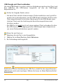
USB Dongleserver myUTN-800 Quick Installation Guide Overview [en] Überblick [de] This Quick Installation Guide provides a description of the installation of the myUTN-800. It contains the following information: Dieser Quick Installation Guide beinhaltet eine Beschreibung der Installation des myUTN-800. Sie erhalten die folgenden Informationen: General Information Safety Regulations Hardware Installation Software Installation Getting Started Configuring the UTN Server Locking the UTN Server Mounting in a Rack Allgemeine Information Sicherheitsvorschriften Hardware-Installation Software-Installation Erste Schritte UTN-Server konfigurieren UTN-Server abschließen Im Serverschrank einbauen Please note the table of contents on page 3. Should you have any further questions, please contact our support hotline. Beachten Sie das Inhaltsverzeichnis auf Seite 23. Falls Sie noch Fragen haben, kontaktieren Sie unsere Support-Hotline. @ Monday - Thursday Friday +49 (0)521 94226-44 8:00 a.m. to 4:45 p.m. and 8:00 a.m. to 3:15 p.m. (CET) [email protected] Quick Installation Guide 1 Date of Manufacture The serial number includes the date of manufacture. The serial number can be found on the type plate. 2 Quick Installation Guide 2 General Information . . . . . . . . . . . . . . . . . . . . . . . . . . . . . . 4 Table of Contents Purpose . . . . . . . . . . . . . . . . . . . . . . . . . . . . . . . . . . . . . . . . . . . . . . . . . . 4 Scope of Supply . . . . . . . . . . . . . . . . . . . . . . . . . . . . . . . . . . . . . . . . . . 4 Accessories. . . . . . . . . . . . . . . . . . . . . . . . . . . . . . . . . . . . . . . . . . . . . . . 5 Technical Data . . . . . . . . . . . . . . . . . . . . . . . . . . . . . . . . . . . . . . . . . . . 6 LED Display . . . . . . . . . . . . . . . . . . . . . . . . . . . . . . . . . . . . . . . . . . . . . . 7 Display panel. . . . . . . . . . . . . . . . . . . . . . . . . . . . . . . . . . . . . . . . . . . . . 7 2 Safety Regulations . . . . . . . . . . . . . . . . . . . . . . . . . . . . . . . 8 2 Hardware Installation. . . . . . . . . . . . . . . . . . . . . . . . . . . . . 9 2 Software Installation . . . . . . . . . . . . . . . . . . . . . . . . . . . . 10 2 Getting Started: SEH UTN Manager . . . . . . . . . . . . . . . 12 Starting the SEH UTN Manager . . . . . . . . . . . . . . . . . . . . . . . . . . .13 Assigning an IP Address to the UTN Server . . . . . . . . . . . . . . .14 Adding the UTN Server to the Selection List . . . . . . . . . . . . . .15 Connecting the USB Dongle to the Client. . . . . . . . . . . . . . . . .16 2 Configuring the UTN Server . . . . . . . . . . . . . . . . . . . . . . 17 2 Locking the UTN Server . . . . . . . . . . . . . . . . . . . . . . . . . . 18 2 Mounting the UTN Server in a Rack . . . . . . . . . . . . . . . 19 Tools Required . . . . . . . . . . . . . . . . . . . . . . . . . . . . . . . . . . . . . . . . . .19 Prior to Mounting . . . . . . . . . . . . . . . . . . . . . . . . . . . . . . . . . . . . . . .19 Mounting the UTN server . . . . . . . . . . . . . . . . . . . . . . . . . . . . . . . .20 Quick Installation Guide [en] 3 General Information Purpose The Dongleserver 'myUTN-800' gives network participants access to USB dongles. The USB dongles will be connected to the USB ports of the myUTN-800. The software tool ’SEH UTN Manager’ handles the access to the USB dongles. The SEH UTN Manager is installed on all clients that are intended to access a USB dongle in the network. The SEH UTN Manager shows the availability of all UTN servers in the network and establishes a connection between the client and the USB port including the connected USB dongle. The lockable housing cover on the Dongleserver allows for a central and safe storage of the USB dongles. The myUTN-800 itself can be mounted in a 19" server rack. The administration of the myUTN-800 is done via the 'myUTN Control Center'. Scope of Supply Please check the package content before getting started: 4 UTN server Dongleserver 'myUTN-800' Quick Installation Guide The Quick Installation Guide provides a brief description of the installation of the myUTN-800. (This document) 2 Power cords Power supply cable 2 Mounting brackets 65.5 mm × 43 mm × 29.8 mm 4 Screws M4 × 4 mm SD card Inserted into SD card reader. [en] Quick Installation Guide Accessories Value-adding accessories for your myUTN-800 are optionally available from SEH. myUTN-800 Serviceplus package The 'myUTN-800 Serviceplus package' extends the manufacturer's guarantee of your myUTN-800 from 36 to 60 months. In addition, you will receive quickly and easily an advance replacement device in case of a defect! http://www.seh-technology.com/services/ service-packages/myutn-800.html Scan this QR code using your smart phone to get direct access to the homepage. RMK3 (Rack Mount Kit Type 3) For a perfect and safe storage of your myUTN800 we recommend the Rack Mount Kit RMK3. Using the Rack Mount Kit, you can mount the myUTN-800 into 19" server racks. Contrary to the mounting brackets included in delivery, the RMK3 allows for a comfortable access to the UTN server via telescopic slides. http://www.seh-technology.com/products/ rack-mount-kits.html Scan this QR code using your smart phone to get direct access to the homepage. Quick Installation Guide [en] 5 Technical Data 1) Network connector 1 (RJ-45) 5) Segment display 10) Power supply 1 6) SD card reader 2) Network connector 2 (RJ-45) 7) Reset button 11) Hole for the RMK3 cable fixture 8) Restart button 12) Power supply 2 3) Activity LED (yellow) 4) Status LED (green) Properties 9) USB ports 1–20 with USB port LEDs Values Network connection logical: physical: Device connection - IEEE 802.3 (1000BaseT, 100BaseTX and 10BaseT) - 2 × RJ-45 - 20 × USB 2.0 Hi-Speed - 1 × SD Card reader Current input per supply max 1.3 A at 100–240 VAC (with full load on the USB ports) Operating environment - Ambient temperature: 5–40 °C - Relative humidity: 20–80 % Dimensions - Width: Height: Depth: Weight: 422 mm 44 mm 243 mm 2950 g with housing cover, without mounting brackets (Suitable for 19" server racks.) 6 [en] Quick Installation Guide LED Display The LEDs of the UTN server provide information about its status. LED Action Color Description Activity permanently off - If the status LED blinks periodically at the same time, the BIOS mode is signalized. Status permanently off - If the activity LED blinks periodically at the same time, the BIOS mode is signalized. blinks 3 times green Indicates the assignment of a ZeroConfig IP address. blinks 2 times green Indicates the assignment of an IP address that does not correspond to 0.0.0.0 or that comes from outside the ZeroConf range. permanently off - No USB dongle is connected to the respective port. permanently on green A USB dongle is connected to the respective port. permanently on orange The connection to the respective port and the attached USB dongle is activated. USB ports 1–20 Display panel The display panel on the front of the UTN server provides status information. Text Description DS (Identifier) The Dongleserver is ready to operate. E1 One of the two power supplies is not working. Which connection is not working is indicated by a glowing dot (left dot, left power supply; right dot, right power supply). E2 The SD card is formatted with an unsupported file system respectively cannot be read and be written to. E3 The SD card is read-only. E4 No SD card is available in the card reader. E5 One or both network connections have no link. Quick Installation Guide [en] 7 Safety Regulations UTN servers are network devices for use in office environments. The myUTN-800 is designed for the integration of USB dongles into TCP/IP networks. Before starting the initial setup procedure and during the operation of the UTN server, please note the following safety regulations. Their purpose is to protect yourself and others from personal injuries, and avoid damage to the equipment. Read the documentation and make sure that your system meets the 8 requirements listed therein. The device must only be connected to the mains and to the network by qualified personnel. Avoid contact with humidity or liquids. The device must only be connected and operated if it is in perfect condition. Make sure that no-one steps on or stumbles over the cables. If the supplied power cords cannot be used in your country, acquire two appropriate power cords that suit national provisions. For more information, please consult your retailer. The device must be connected to two sockets with safety contact. Position the device in a way that guarantees that the two sockets for the connection of the power cords are in the proximity of the device and are easily accessible. Make sure that the device can be separated easily from the mains. A damaged power cord must be replaced immediately. For more information, please consult your retailer. To disconnect the device from the mains, both power cords must be separated from the device. Do not connect telephone cables to the RJ-45 connectors. The RJ-45 connectors may only be connected to SELV voltages. For the connection to the RJ-45 connectors only STP cabling (category 5 or better) may be used. The shielding must fit flushly to the connectors. Do not open the housing. Unauthorized modifications to the device can affect the product certification and are forbidden. [en] Quick Installation Guide Hardware Installation You can directly connect up to twenty USB dongles to the UTN server (myUTN800). clients with the software tool 'SEH UTN Manager' network myUTN-800 USB 2.0 Hi-Speed dongles Proceed as follows: 1. Connect the USB dongle to a USB port of the UTN server. (Repeat this step if you want to connect more than one USB dongle.) 2. Connect the two network cables (RJ-45) to the UTN server. 3. Connect the two power cords to the UTN server. Do not remove the SD card from the UTN server. Upon delivery, the SD card is already inserted into the SD card reader and ready for use (installation or formatting are not required). Quick Installation Guide [en] 9 Software Installation The software tool SEH UTN Manager handles the access to the USB dongles. The SEH UTN Manager is available in two versions: Complete version Minimal version (only command-line interface) The complete version has a graphical user interface and offers additional features. A detailed description can be found in the myUTN User Manual. The SEH UTN Manager is installed on all clients that are intended to access a USB dongle in the network. Different installation files are available, depending on the operating system. First, you have to download the installation file for the SEH UTN Manager from the homepage of SEH Computertechnik GmbH: http://www.seh-technology.com/services/downloads/ download-dongleserver/myutn-800.html Scan this QR code using your smart phone to get direct access to the homepage. System requirements: - Windows XP or later; OS X 10.8.x or later - The installation can only be carried out by users with administrative rights. The SEH UTN Manager is also available for selected Linux systems. All information necessary for installing and using the SEH UTN Manager in Linux environments can be found in the myUTN User Manual Linux. The documentation is available via the link given above. 10 [en] Quick Installation Guide Proceed as follows: 1. Start the installation file. 2. Install the complete version of the SEH UTN Manager (including graphical user interface). Follow the installation routine. The SEH UTN Manager is installed on your client. Quick Installation Guide [en] 11 Getting Started: SEH UTN Manager After the SEH UTN Manager is started, the network will be scanned for connected UTN servers. The network range to be scanned is freely definable. All UTN servers found will be shown in the 'network list' together with the connected USB dongles. The required UTN servers will be selected and added to the 'selection list'. The UTN servers listed in the selection list and the connected USB dongles can then be used by the user. This chapter describes the first steps with the program. ’Starting the SEH UTN Manager’ 13 ’Assigning an IP Address to the UTN Server’ 14 ’Adding the UTN Server to the Selection List’ 15 ’Connecting the USB Dongle to the Client’ 16 Detailed information on how to use the SEH UTN Manager can be found in the Online Help. To start the Online Help, select Help – Online Help from the menu bar. Client and UTN server communicate via the UTN port 9200. This port must not be blocked by a firewall. If necessary, you can change the port number and use a secure UTN SSL port. A detailed description can be found in the myUTN User Manual. 12 [en] Quick Installation Guide Starting the SEH UTN Manager Windows Start the SEH UTN Manager on your client via the Windows start menu. (Start All Programs SEH Computertechnik GmbH SEH UTN Manager) Mac To start the program, double-click the 'SEH UTN Manager.app' file. (Applications SEH UTN Manager.app) During the initial configuration, client and UTN server must be assigned to the same local network segment. Quick Installation Guide [en] 13 Assigning an IP Address to the UTN Server Once the UTN server is connected to the network, it checks whether an IP address can be obtained from the boot protocols BOOTP or DHCP. If this is not the case, the UTN server assigns itself an IP address via ZeroConf from the address range (169.254.0.0/16) which is reserved for ZeroConf. The UTN servers found by the program will be displayed in the network list. You can change the TCP/IP parameters of the UTN server. Proceed as follows: 1. Confirm the note dialog 'Your Selection List seems to be empty' by clicking Yes. If no note dialog is available and the main dialog appears, select Selection List – Edit from the menu bar. 2. 3. 4. 5. 14 The Edit Selection List dialog appears. Select the UTN server from the network list. Select Set IP Address from the shortcut menu. The Set IP Address dialog appears. Enter the relevant TCP/IP parameters. Click OK. The settings are saved. [en] Quick Installation Guide Adding the UTN Server to the Selection List The selection list displays the UTN servers and the USB dongles connected to their USB ports. Define the devices you want to use. To do this, you must add the UTN server (and the connected USB dongles) shown in the network list to the selection list. 1. 2. 3. 4. Proceed as follows: Select Selection List – Edit from the menu bar. The Edit Selection List dialog appears. Select the UTN server from the network list. Click Add. (Repeat steps 2 and 3, if necessary.) Click OK. The UTN servers are shown in the selection list. You can extend the search for UTN servers to any network range. To do this, change the search parameters for the network scan. Windows: via the Options dialog in the Program menu. Mac: via the Preferences dialog in the SEH UTN Manager menu. Quick Installation Guide [en] 15 Connecting the USB Dongle to the Client To use a USB dongle, a connection is established between the client and the USB port of the UTN server to which the USB dongle is connected. Make sure that: - All provisions (driver installation, etc.) that would be necessary to operate the USB dongle locally (i.e. connected directly to the client) have been met on the client. Ideally, the USB dongle has been connected and operated on the client locally according to the instructions of the manufacturer. - The USB port is not connected to another client. A USB dongle that was made available by the UTN server can only be used by one network participant at a time. Proceed as follows: 1. Select the port from the selection list. 2. Select Port – Activate from the menu bar. The connection will be established. Close the connection to the USB port when the connected USB dongle is no longer needed. Select Port – Deactivate from the menu bar. 16 [en] Quick Installation Guide Configuring the UTN Server The UTN server can be configured and monitored via the myUTN Control Center. The myUTN Control Center is stored in the UTN server and can be launched by means of a browser (Internet Explorer, Mozilla Firefox, Safari). Proceed as follows: 1. Open your browser. 2. Enter the IP address of the UTN server as the URL. The myUTN Control Center appears in the browser. If the myUTN Control Center is not displayed, check the proxy settings of your browser. Detailed information about the configuration of the UTN server can be found in the Online Help of the myUTN Control Center. To start the Online Help, click the '?' icon. Quick Installation Guide [en] 17 Locking the UTN Server The lockable housing cover on the dongle server allows for a central and safe storage of the connected USB dongles. To close the cover, insert the three straps of the housing cover into the notches of the housing. Use the key provided to activate the locking mechanism. 18 [en] Quick Installation Guide Mounting the UTN Server in a Rack For a perfect and safe storage of the UTN server, we recommend installing it in a 19" server rack: You can mount the UTN server myUTN-800 in a 19" server rack with the two mounting brackets included in delivery. For a more comfortable handling, we recommend the Rack Mount Kit 3 (RMK3); see: ’Accessories’ 5. Mounting the UTN server in a 19" server rack using the mounting brackets included in delivery must only be done in the way described in this document. Tools Required: 2 mounting brackets (included in delivery) 4 screws (M4 × 4 mm) (included in delivery) Slotted screwdriver Phillips screwdriver Fasteners for mounting the UTN server in the server rack (not included in delivery) Prior to Mounting: 1. 2. 3. 4. 5. 6. Proceed as follows: Read and observe the safety regulations about the UTN server ( 8) and server rack. Check the size and settings of your rack unit and compare the data with those of the mounting brackets. Remove both power cords from the UTN server (interrupt the power supply). Remove both network cables (RJ-45) from the UTN server. Place the UTN server upside down on a solid surface. Remove all rubber feet of the UTN server: Remove the pin from each rubber foot using a small slotted screwdriver. The rubber foot detaches automatically. (Please keep the pins and rubber feet in a safe place for potential future use.) 7. Turn the myUTN-800 around again. Quick Installation Guide [en] 19 Mounting the UTN server: 1. 2. 3. 4. Proceed as follows: Place the UTN server on a solid surface. Hold one mounting bracket to the side of the UTN server in such a way that the two holes in the mounting bracket align with the holes in the UTN server. The short mounting bracket wing faces away from the UTN server. Fasten the mounting bracket to the UTN server by inserting and tightening two provided screws (M4 × 4 mm) in the holes of the UTN server. Repeat steps 2 and 3 on the opposite side of the UTN server. 5. Install the UTN server in the server rack. To do this, fasten the mounting brackets of the UTN server to the server rack posts. 6. Connect the network cables (RJ-45) to the UTN server. 7. Connect the power cords to the UTN server (establish the power supplies). 20 [en] Quick Installation Guide Quick Installation Guide [en] 21 22 [en] Quick Installation Guide 2 Allgemeine Information . . . . . . . . . . . . . . . . . . . . . . . . . 24 Inhaltsverzeichnis Verwendungszweck . . . . . . . . . . . . . . . . . . . . . . . . . . . . . . . . . . . . .24 Lieferumfang . . . . . . . . . . . . . . . . . . . . . . . . . . . . . . . . . . . . . . . . . . . .24 Optionales Zubehör . . . . . . . . . . . . . . . . . . . . . . . . . . . . . . . . . . . . .25 Technische Daten . . . . . . . . . . . . . . . . . . . . . . . . . . . . . . . . . . . . . . .26 LED-Anzeige . . . . . . . . . . . . . . . . . . . . . . . . . . . . . . . . . . . . . . . . . . . .27 Anzeigefeld . . . . . . . . . . . . . . . . . . . . . . . . . . . . . . . . . . . . . . . . . . . . .27 2 Sicherheitsvorschriften . . . . . . . . . . . . . . . . . . . . . . . . . . 28 2 Hardware-Installation . . . . . . . . . . . . . . . . . . . . . . . . . . . 29 2 Software-Installation . . . . . . . . . . . . . . . . . . . . . . . . . . . . 30 2 Erste Schritte mit dem SEH UTN Manager . . . . . . . . . 32 SEH UTN Manager starten. . . . . . . . . . . . . . . . . . . . . . . . . . . . . . . .33 UTN-Server eine IP-Adresse zuweisen . . . . . . . . . . . . . . . . . . . .34 UTN-Server der Auswahlliste hinzufügen . . . . . . . . . . . . . . . . .35 USB-Dongle mit Client verbinden . . . . . . . . . . . . . . . . . . . . . . . .36 2 UTN-Server konfigurieren. . . . . . . . . . . . . . . . . . . . . . . . 37 2 UTN-Server abschließen . . . . . . . . . . . . . . . . . . . . . . . . . 38 2 UTN-Server in einen Serverschrank einbauen . . . . . 39 Das benötigen Sie . . . . . . . . . . . . . . . . . . . . . . . . . . . . . . . . . . . . . . .39 Vor dem Einbau . . . . . . . . . . . . . . . . . . . . . . . . . . . . . . . . . . . . . . . . .39 Einbau . . . . . . . . . . . . . . . . . . . . . . . . . . . . . . . . . . . . . . . . . . . . . . . . . .40 Quick Installation Guide [de] 23 Allgemeine Information Verwendungszweck Der Dongleserver 'myUTN-800' stellt den Zugriff auf USB-Dongles mehreren Netzwerkteilnehmern zur Verfügung. Dazu werden die USB-Dongles an die USBPorts des myUTN-800 angeschlossen. Die Zugriffsverteilung der USB-Dongles erfolgt über das Software-Tool 'SEH UTN Manager'. Der SEH UTN Manager wird auf allen Clients installiert, die auf einen im Netzwerk bereitgestellten USB-Dongle zugreifen sollen. Der SEH UTN Manager zeigt die Verfügbarkeit aller im Netzwerk eingebundenen UTN-Server an und stellt die Verbindung zwischen Client und USB-Port inklusive dem daran angeschlossenen USB-Dongle her. Der abschließbare Gehäusedeckel am Dongleserver ermöglicht eine zentrale und sichere Aufbewahrung der USB-Dongles. Der myUTN-800 selbst kann fest in einem 19-Zoll-Serverschrank verbaut werden. Die Verwaltung des myUTN-800 erfolgt über das 'myUTN Control Center'. Lieferumfang Bitte überprüfen Sie den Packungsinhalt auf Vollständigkeit, bevor Sie die Installation beginnen: 24 UTN-Server Dongleserver 'myUTN-800' Quick Installation Guide Der Quick Installation Guide beinhaltet eine kurze Beschreibung der Installation des myUTN-800. (Dieses Dokument) 2 Netzkabel Stromversorgungskabel 2 Befestigungswinkel 65,5 mm × 43 mm × 29,8 mm 4 Schrauben M4 × 4 mm SD-Karte In SD-Card-Reader eingesteckt. [de] Quick Installation Guide Optionales Zubehör Als praktische Ergänzung zu Ihrem myUTN-800 bietet SEH optional erhältliches Zubehör an. myUTN-800 ServiceplusPaket Das 'myUTN-800 Serviceplus-Paket' verlängert die Herstellergarantie Ihres myUTN-800 von 36 auf 60 Monate. Zudem erhalten Sie im Falle eines Defektes bequem und schnell ein VorabAustausch-Gerät. http://www.seh.de/services/service-pakete/ myutn-800.html Scannen Sie diesen QR-Code mit Ihrem Smartphone, um direkt zur Homepage zu gelangen. RMK3 (Rack Mount Kit Type 3) Für die optimale und sichere Aufbewahrung Ihres myUTN-800 empfehlen wir den Montagesatz 'RMK3'. Der Montagesatz ermöglich den Einbau des myUTN-800 in 19-Zoll-Serverschränke. Im Gegensat zu den beigelegten Befestigungswinklen ermöglicht das RMK3 einen komfortablen Zugang zum UTN-Server über ausziehbare Teleskopschienen. http://www.seh.de/produkte/ rack-mount-kits.html Scannen Sie diesen QR-Code mit Ihrem Smartphone, um direkt zur Homepage zu gelangen. Quick Installation Guide [de] 25 Technische Daten 1) Netzwerkanschluss 1 (RJ-45) 5) Anzeigefeld 10) Stromversorgung 1 6) SD-Card-Reader 2) Netzwerkanschluss 2 (RJ-45) 7) Reset-Taster 11) Loch für Kabelfestigung des RMK3 8) Restart-Taster 12) Stromversorgung 2 3) Activity-LED (gelb) 9) USB-Ports 1–20 mit LED für USB-Port 4) Status-LED (grün) Eigenschaften Werte Netzwerkanschluss Logisch: Physisch: Geräteanschluss - IEEE 802.3 (1000BaseT, 100BaseTX und 10BaseT) - 2 × RJ-45 - 20 × USB 2.0 Hi-Speed - 1 × SD-Card-Reader Stromaufnahme pro Anschluss max. 1,3 A bei 100–240 VAC (bei Volllast auf den USB-Ports) Betriebsumgebung - Umgebungstemperatur: 5–40 °C - Relative Luftfeuchtigkeit: 20–80 % Abmessungen - Breite: 422 mm Höhe: 44 mm Tiefe: 243 mm Gewicht: 2950 g mit Gehäusedeckel, ohne Montagewinkel (Passend für 19-Zoll-Serverschränke.) 26 [de] Quick Installation Guide LED-Anzeige Durch die Interpretation des LED-Leuchtverhaltens kann der Zustand des UTNServers ermittelt werden. LED Aktion Farbe Beschreibung Activity Dauer-Aus - Bei gleichzeitigem zyklischen Blinken der Activity-LED wird der BIOS-Modus signalisiert. Status Dauer-Aus - Bei gleichzeitigem zyklischen Blinken der Activity-LED wird der BIOS-Modus signalisiert. 3 x Blinken grün Signalisiert die Vergabe einer ZeroConfig-IPAdresse. 2 x Blinken grün Signalisiert die Vergabe einer IP-Adresse, die nicht 0.0.0.0 entspricht oder aus dem Bereich ZeroConfig kommt. Dauer-Aus - Es ist kein USB-Dongle am betreffenden Port angeschlossen. Dauer-An grün Es ist ein USB-Dongle am betreffenden Port angeschlossen. Dauer-An orange Die Verbindung zum betreffenden Port und dem daran angeschlossenen USB-Dongle ist aktiviert. USB-Port 1–20 Anzeigefeld Das Anzeigefeld an der Vorderseite des UTN-Servers stellt Statusinformationen zur Verfügung. Text Beschreibung DS (Kennung) Der Dongleserver ist betriebsbereit. E1 Eine der beiden Stromversorgungen ist ausgefallen. Welcher Anschluss betroffen ist, zeigt der leuchtende Punkt (linker Punkt, linke Stromversorgung; rechter Punkt, rechte Stromversorgung). E2 Die SD-Karte ist in einem nicht unterstützten Dateisystem formatiert bzw. ist nicht lesbar und nicht beschreibbar. E3 Die SD-Karte ist lesbar aber nicht beschreibbar. E4 Es ist keine SD-Karte im SD-Card-Reader vorhanden. E5 Eine oder beide Netzwerkverbindungen sind getrennt. Quick Installation Guide [de] 27 Sicherheitsvorschriften UTN-Server sind Netzwerkgeräte für den Gebrauch in Büroumgebungen. Der myUTN-800 dient dem Einbinden von USB-Dongles in TCP/IP-Netzwerken. Beachten Sie vor Inbetriebnahme und beim Betrieb des UTN-Servers die folgenden Sicherheitsvorschriften, um sich und andere vor Personenschäden zu schützen sowie Beschädigungen am Gerät zu vermeiden. Lesen Sie die Dokumentation und stellen Sie sicher, dass Ihr System den 28 aufgeführten Anforderungen entspricht. Das Gerät darf nur von qualifiziertem Fachpersonal angeschlossen und mit dem Netzwerk verbunden werden. Das Gerät darf nicht mit Feuchtigkeit oder Flüssigkeit in Berührung kommen. Das Gerät darf nur in unversehrtem Zustand angeschlossen und betrieben werden. Verlegen Sie alle Kabel so, dass niemand darauf treten oder darüber stolpern kann. Falls die beiliegenden Netzkabel für Ihr Land nicht einsetzbar sind, beschaffen Sie zwei passende Netzkabel mit der jeweiligen nationalen Zulassung. Fragen Sie hierzu Ihren Fachhändler. Das Gerät muss an zwei Steckdosen mit Schutzkontakt angeschlossen werden. Stellen Sie das Gerät so auf, dass die zwei Steckdosen für den Anschluss der Netzkabel in der Nähe des Gerätes und leicht zugänglich sind. Das Gerät muss leicht vom Netz zu trennen sein. Ein beschädigtes Netzkabel muss sofort ersetzt werden. Fragen Sie hierzu Ihren Fachhändler. Zum Trennen des Gerätes vom Netz müssen beide Netzkabel vom Gerät entfernt werden. Schließen Sie keine Telefonleitungen an die zwei RJ-45-Stecker an. An diese darf nur Sicherheitskleinspannung angeschlossen werden. Verwenden Sie für den Anschluss an die RJ-45-Stecker nur STP-Kabel (Kategorie 5 oder besser). Kabelschirm und Steckerschirm der Kabel müssen flächig verbunden sein. Öffnen Sie nicht das Gehäuse. Eigenmächtige konstruktive Veränderungen am Gerät können die Produktzertifizierung beeinträchtigen und sind verboten. [de] Quick Installation Guide Hardware-Installation Am UTN-Server (myUTN-800) können bis zu zwanzig USB-Dongles direkt angeschlossen werden. Clients mit Software-Tool 'SEH UTN Manager' Netzwerk myUTN-800 USB 2.0 Hi-Speed Dongles Gehen Sie wie folgt vor: 1. Stecken Sie den USB-Dongle an einen USB-Port des UTN Servers. (Wiederholen Sie diesen Schritt je nach Anzahl der anzuschließenden USB-Dongles.) 2. Verbinden Sie die zwei Netzwerkkabel (RJ-45) mit dem UTNServer. 3. Verbinden Sie die zwei Netzkabel mit dem UTN-Server. Entfernen Sie nicht die SD-Karte aus dem UTN-Server. Die SD-Karte befindet sich bei Auslieferung bereits im SD-Card-Reader und ist betriebsbereit (kein Anschließen oder Formatieren erforderlich). Quick Installation Guide [de] 29 Software-Installation Die Zugriffsverteilung der USB-Dongles wird über das Software-Tool SEH UTN Manager organisiert. Der SEH UTN Manager ist in zwei Varianten verfügbar: Vollständige Variante Minimal-Variante (reine Kommandozeilen-Version) Die vollständige Variante verfügt über eine grafische Bedienoberfläche und bietet zusätzliche Funktionen. Detaillierte Beschreibungen finden Sie in der myUTN-Benutzerdokumentation. Der SEH UTN Manager wird auf allen Clients installiert, die auf einen im Netzwerk bereitgestellten USB-Dongle zugreifen sollen. Je nach Betriebssystem sind verschiedene Installationsdateien verfügbar. Bitte laden Sie zuerst die Installationsdatei für den SEH UTN Manager von der SEH Computertechnik GmbH-Homepage: http://www.seh.de/services/downloads/downloaddongleserver/myutn-800.html Scannen Sie diesen QR-Code mit Ihrem Smartphone, um direkt zur Homepage zu gelangen. Systemvoraussetzungen: - Windows XP oder höher; OS X 10.8.x oder höher - Die Installation kann ausschließlich durch Benutzer mit administrativen Rechten durchgeführt werden. Der SEH UTN Manager ist auch für ausgewählte Linux-Systeme verfügbar. Alle Informationen für die Installation und den Einsatz in Linux-Umgebungen finden Sie in der myUTN-Benutzerdokumentation Linux. Die Dokumentation finden Sie unter dem oben angegebenen Link. 30 [de] Quick Installation Guide Gehen Sie wie folgt vor: 1. Starten Sie die Installationsdatei. 2. Installieren Sie die vollständige Version des SEH UTN Managers (inkl. grafischer Benutzeroberfläche). Folgen Sie hierzu der Installationsroutine. Der SEH UTN Manager ist auf Ihrem Client installiert. Quick Installation Guide [de] 31 Erste Schritte mit dem SEH UTN Manager Nach dem Start des SEH UTN Managers wird das Netzwerk nach angeschlossenen UTN-Servern gescannt. Der zu scannende Netzwerkbereich ist frei definierbar. Nach dem Scannen des Netzwerks werden alle gefundenen UTN-Server und deren angeschlossene USB-Dongles in der 'Netzwerkliste' angezeigt. Die benötigten UTN-Server werden ausgewählt und der 'Auswahlliste' hinzugefügt. Die in der Auswahlliste aufgeführten UTN-Server und die daran angeschlossenen USB-Dongles können dann vom Benutzer verwendet werden. Dieses Kapitel informiert über die ersten Handlungsschritte mit dem Programm. ’SEH UTN Manager starten’ 33 ’UTN-Server eine IP-Adresse zuweisen’ 34 ’UTN-Server der Auswahlliste hinzufügen’ 35 ’USB-Dongle mit Client verbinden’ 36 Detaillierte Informationen zur Bedienung des SEH UTN Managers entnehmen Sie der Online Hilfe. Um die Online Hilfe zu starten wählen Sie im Menü Hilfe den Befehl Online Hilfe. Client und UTN-Server kommunizieren über den UTN-Port 9200. Dieser Port darf nicht durch eine Sicherheitssoftware (Firewall) blockiert werden. Bei Bedarf kann die Portnummer geändert und ein sicherer UTN-SSL-Port verwendet werden. Detaillierte Beschreibungen finden Sie in der myUTN-Benutzerdokumentation. 32 [de] Quick Installation Guide SEH UTN Manager starten Windows Starten Sie auf Ihrem Client den SEH UTN Manager über das WindowsStartmenü. (Start Alle Programme SEH Computertechnik GmbH SEH UTN Manager) Mac Zum Starten des Programms doppelklicken Sie auf die Datei 'SEH UTN Manager.app'. (Programme SEH UTN Manager.app) Während der Erstkonfiguration müssen Client und UTN-Server demselben lokalen Netzwerksegment zugeordnet sein. Quick Installation Guide [de] 33 UTN-Server eine IP-Adresse zuweisen Nachdem der UTN-Server an das Netzwerk angeschlossen ist, überprüft der UTNServer, ob er eine IP-Adresse über die Bootprotokolle BOOTP oder DHCP erhält. Ist das nicht der Fall, gibt sich der UTN-Server über ZeroConf selbst eine IP-Adresse aus dem für ZeroConf reservierten Adressbereich (169.254.0.0/16). Die vom Programm gefundenen UTN-Server werden in der Netzwerkliste angezeigt. Sie haben die Möglichkeit, die TCP/IP-Parameter am UTN-Server zu ändern. Gehen Sie wie folgt vor: 1. Bestätigen Sie den Hinweisdialog 'Auswahlliste ist leer' mit Ja. Falls kein Hinweisdialog vorhanden ist und der Hauptdialog angezeigt wird, wählen Sie im Menü Auswahlliste den Befehl Bearbeiten. 2. 3. 4. 5. 34 Der Dialog Auswahlliste bearbeiten erscheint. Markieren Sie den UTN-Server in der Netzwerkliste. Wählen Sie IP-Adresse definieren im Kontextmenü. Der Dialog IP-Adresse definieren erscheint. Geben Sie die entsprechenden TCP/IP-Parameter ein. Wählen Sie die Schaltfläche OK an. Die Einstellungen werden gespeichert. [de] Quick Installation Guide UTN-Server der Auswahlliste hinzufügen Die Auswahlliste zeigt die UTN-Server und die an ihre USB-Ports angeschlossenen USB-Dongles an. Definieren Sie die Geräte, die Sie nutzen möchten. Fügen Sie hierzu den in der Netzwerkliste angezeigten UTN-Server mitsamt seinen angeschlossenen USBDongles der Auswahlliste hinzu. 1. 2. 3. 4. 5. Gehen Sie wie folgt vor: Wählen Sie im Menü Auswahlliste den Befehl Bearbeiten. Der Dialog Auswahlliste bearbeiten erscheint. Markieren Sie den UTN-Server in der Netzwerkliste. Wählen Sie die Schaltfläche Hinzufügen an. (Wiederholen Sie die Schritte 2-3 nach Bedarf.) Wählen Sie die Schaltfläche OK an. Die UTN-Server werden in der Auswahlliste angezeigt. Die Suche nach UTN-Servern kann auf beliebige Netzwerkbereiche erweitert werden. Ändern Sie hierzu die Suchparameter für den Netzwerkscan. Windows: Im Menü Programm über den Dialog Optionen. Mac: Im Menü SEH UTN Manager über den Dialog Einstellungen. Quick Installation Guide [de] 35 USB-Dongle mit Client verbinden Um einen USB-Dongle zu nutzen, wird eine Verbindung zwischen dem Client und dem USB-Port des UTN-Servers hergestellt, an den der USB-Dongle angeschlossen ist. Stellen Sie folgende Punkte sicher: - Auf dem Client sind alle Vorbereitungen (Treiberinstallation usw.) getroffen worden, die notwendig wären, um den USB-Dongle lokal (also direkt an dem Client angeschlossen) zu betreiben. Idealerweise ist der USB-Dongle zuvor lokal am Client nach der Anleitung des Herstellers angeschlossen und betrieben worden. - Der USB-Port ist nicht bereits mit einem anderen Client verbunden. Ein über den UTN-Server zur Verfügung gestellter USB-Dongle kann zeitgleich nur von einem Netzwerkteilnehmer genutzt werden. Gehen Sie wie folgt vor: 1. Markieren Sie den Port in der Auswahlliste . 2. Wählen Sie im Menü Port den Befehl Aktivieren. Die Verbindung wird hergestellt. Deaktivieren Sie die Verbindung zum USB-Port, sobald Sie den angeschlossenen USB-Dongle nicht mehr benötigen. Wählen Sie hierzu im Menü Port den Befehl Deaktivieren. 36 [de] Quick Installation Guide UTN-Server konfigurieren Über das myUTN Control Center kann der UTN-Server konfiguriert und überwacht werden. Das myUTN Control Center ist in dem UTN-Server gespeichert und kann mit einem Internet-Browser (Internet Explorer, Firefox, Safari) aufgerufen werden. Gehen Sie wie folgt vor: 1. Öffnen Sie Ihren Browser. 2. Geben Sie als URL die IP-Adresse des UTN-Servers ein. Das myUTN Control Center wird im Browser dargestellt. Falls das myUTN Control Center nicht angezeigt wird, überprüfen Sie die ProxyEinstellungen Ihres Browsers. Detaillierte Informationen zur Konfiguration des UTN-Servers entnehmen Sie der Online Hilfe des myUTN Control Centers. Um die Online Hilfe zu starten wählen Sie das '?'-Symbol an. Quick Installation Guide [de] 37 UTN-Server abschließen Der abschließbare Gehäusedeckel am Dongleserver ermöglicht eine zentrale und sichere Aufbewahrung der angeschlossenen USB-Dongles. Zum Schließen werden die drei Laschen des Gehäusedeckels in die Nuten des Gehäuses eingeführt. Mit dem mitgelieferten Schlüssel kann die Schließvorrichtung aktiviert werden. 38 [de] Quick Installation Guide UTN-Server in einen Serverschrank einbauen Für die optimale und sichere Aufbewahrung des UTN-Servers empfehlen wir, den UTN-Server myUTN-800 in einen 19-Zoll-Serverschrank einzubauen: Mit den mitgelieferten Befestigungswinkeln kann der UTN-Server myUTN-800 fest in einem 19-Zoll-Serverschrank verbaut werden. Für eine komfortablere Handhabung empfehlen wir den Montagesatz Rack Mount Kit 3 (RMK3); siehe: ’Optionales Zubehör’ 25. Der Einbau des UTN-Servers in einen 19-Zoll-Serverschrank mithilfe der Befestigungswinkel darf nur auf die in diesem Dokument beschriebene Weise erfolgen. Das benötigen Sie: 2 Befestigungswinkel (im Lieferumfang enthalten) 4 Schrauben (M4 × 4 mm) (im Lieferumfang enthalten) Schlitzschraubenzieher Kreuzschlitzschraubenzieher Material zur Befestigung im Serverschrank (nicht im Lieferumfang enthalten) Vor dem Einbau: Gehen Sie wie folgt vor: 1. Lesen und beachten Sie die Sicherheitsvorschriften zu Ihrem UTN-Server ( 28) und Ihrem Serverschrank. 2. Überprüfen Sie die Maße und Gegebenheiten (Einstellungen) Ihres Serverschranks und vergleichen Sie die Daten mit denen der Einbauwinkel. 3. Entfernen Sie beide Netzkabel vom UTN-Server (Stromzufuhr unterbrechen). 4. Lösen Sie beide Netzwerkkabel (RJ-45) vom UTN-Server. 5. Platzieren Sie den UTN-Server kopfüber auf eine feste Auflage. 6. Entfernen Sie alle Füße des UTN-Servers: Hebeln Sie mit einem kleinen Schlitzschraubenzieher den Stift aus jedem Fuß heraus. Der Fuß löst sich automatisch. (Bewahren Sie Stifte und Füße für einen eventuellen zukünftigen Einsatz gut auf.) 7. Drehen Sie den UTN-Server wieder herum. Quick Installation Guide [de] 39 Einbau 1. 2. 3. 4. Gehen Sie wie folgt vor: Platzieren Sie den UTN-Server auf einer festen Auflage. Halten Sie einen Befestigungswinkel seitlich neben den UTN-Server, so dass die zwei Löcher im Befestigungswinkel an den Bohrungen im UTN-Server ausgerichtet sind. Der kurze Flügel zeigt vom UTN-Server weg. Fixieren Sie die den Befestigungswinkel mit 2 mitgelieferten Schrauben (M4 × 4 mm) an den Bohrungen im UTN-Server. Wiederholen Sie die Schritte 2 und 3 auf der gegenüberliegenden Seite des UTN-Servers. 5. Installieren Sie den myUTN-800 im Serverschrank. Fixieren Sie dazu den UTN-Server mit den Befestigungswinkeln am Lochraster des Serverschranks. 6. Verbinden Sie die Netzwerkkabel (RJ-45) mit dem UTN-Server. 7. Verbinden Sie die Netzkabel mit dem UTN-Server (Stromzufuhr herstellen). 40 [de] Quick Installation Guide Quick Installation Guide [de] 41 The latest version of the EC declaration of conformity can be downloaded from the homepage of SEH Computertechnik GmbH: http://www.seh-technology.com/services/ce-notifications.html 42 Quick Installation Guide Quick Installation Guide 43 Manufactured by: SEH Computertechnik GmbH Scan this QR code (meCard) using your smart phone. Suedring 11 33647 Bielefeld Germany Phone: +49 (0)521 94226-29 Fax: +49 (0)521 94226-99 Support: +49 (0)521 94226-44 Email: [email protected] Web: http://www.seh.de Document: Type: Quick Installation Guide Title: myUTN-800 Version: 1.4 Order number: MHAB-QI-myUTN800 Online Links to important Internet Resources: Support Contacts and Information: Sales Contacts and Information: Downloads: http://www.seh-technology.com/support http://www.seh-technology.com/sales http://www.seh-technology.com/services/ downloads.html © 2015 SEH Computertechnik GmbH All trademarks, registered trademarks, logos and product names are property of their respective owners. This product uses ’Open Source Software’. For further information, please contact http://www.seh.de. The product documentation gives you valuable information about your product. Keep the documentation for further reference during the life cycle of the product. 44 Quick Installation Guide