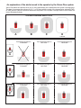
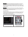
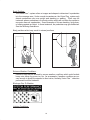
1
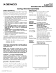
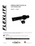
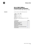
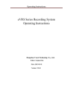
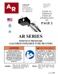
Operating Instructions
This card to be stored with the Vision Plus operator guide in a protected place
on the vehicle within access of the operator. This information must be used
in conjunction with the Vision Plus operator’s guide. Read operator guide
before using this system.
SYSTEM CONFIGURATION
Serial Number:
Model Number:
Date:
Rev:
Init:
SYSTEM COVERAGE AREAS
ÈÈÈÈÈÈÈ
ÈÈÈÈÈÈÈ
ÈÈÈÈÈÈ
ÈÈÈÈÈÈÈ
ÈÈÈÈÈÈ ÈÈÈÈÈÈÈ
ÈÈÈÈÈÈ ÈÈÈÈÈÈÈ
A
B
ÈÈÈÈÈÈÈ
ÈÈÈÈÈÈÈ
ÈÈÈÈÈÈÈ
ÈÈÈÈÈÈÈ
ÈÈÈÈÈÈÈ
ÈÈÈÈÈÈÈ
ÈÈÈÈÈÈÈ
ÈÈÈÈÈÈÈ
ÈÈÈÈÈÈÈ
C
D
COVERAGE AREA RANGE (approximate)
LOW SPEEDS 25 FT
MEDIUM SPEEDS 35 FT
HIGH SPEEDS 45 FT
CAMERA S/N
0: _________________
1: _________________
2: _________________
3: _________________
4: _________________
5: _________________
6: _________________
7: _________________
An explanation of the alerts issued to the operator by the Vision Plus system.
Vision Plus alerts the operator when one or more pedestrians are located within the system coverage area.
The type of coverage area chosen (A, B, C, or D) along with the mode of the transmission selected (FWD,
N, REV) and the vehicle’s speed will determine the portion of the system coverage area for which alerts are
issued (illustrated below).
SYSTEM COVERAGE AREA TYPES
A
B
C
D
CUSTOM
HOW TRANSMISSION MODE (F, N, R) AFFECTS COVERAGE AREA
Transmission Engaged In
FORWARD
Transmission Engaged In
NEUTRAL
Transmission Engaged In
REVERSE
Transmission Engaged In
FORWARD
Transmission Engaged In
NEUTRAL
Transmission Engaged In
REVERSE
Transmission Engaged In
FORWARD
Transmission Engaged In
NEUTRAL
Transmission Engaged In
REVERSE
ÈÈÈÈ
ÈÈÈÈ
ÈÈÈÈ
A
ÈÈÈÈ
ÈÈÈÈ
ÈÈÈÈ
B
ÈÈÈÈ
ÈÈÈÈ
ÈÈÈÈ
ÈÈÈÈ
ÈÈÈÈ
C
Vision Plus is designed to detect pedestrians within a 45ft maximum radius of the machine for all coverage
area types (A, B, C, and D). However, the distance for which alerts are issued to the operator varies with
the vehicle’s speed (illustrated below). Note: All illustrations below depict coverage area Type C.
* Refer to the System Performance section of the operator’s guide, OG-182, for additional coverage area information.
HOW VEHICLE SPEED AFFECTS COVERAGE AREA
LOW SPEEDS: . . . . . . Approx. 25 FT
Alert Issued:
MEDIUM SPEEDS: . . . Approx. 35 FT
Alert NOT Issued:
HIGH SPEEDS: . . . . . . Approx. 45 FT
FORWARD @ LOW SPEEDS
n
X
FORWARD @ HIGH SPEEDS
(25FT COVERAGE AREA RADIUS)
(45FT COVERAGE AREA RADIUS)
n
X
X
n
X
n
X
REARWARD @ MEDIUM SPEEDS
NEUTRAL
(25FT COVERAGE AREA RADIUS)
(35FT COVERAGE AREA RADIUS)
n
X
X
n
n
X
n
n
X
X
Introduction
The Vision Plus pedestrian detection aid is a system designed to aid the operators
of mobile machinery in the location of pedestrians in the vicinity of the vehicle. This
manual is intended to provide the operator with instructions on how to use the
system properly. Because the operator is so vital to safety and production, these
instructions contain important information concerning proper operation of the Vision
Plus system first. This safety information must be understood before operation.
No single piece of information in this manual can be used with the exclusion of the
others. This manual must be read in its entirety. Additionally, these instructions
cannot cover all circumstances that may be encountered.
No one safety device is perfect and can cover all possible situations. Remember!
The most important safety device on the machine is you – the operator. Always look
in the direction of and keep a clear view of the path of travel.
Death or serious injury may occur by improper operation. Do not
operate this system until you have read and understand all operating instructions
and safety information.
End User Terms Of Use
PLEASE READ THE USER MANUAL AND THE IMPORTANT SAFETY INSTRUCTIONS AND WARNINGS
BELOW CAREFULLY BEFORE INSTALLING OR USING VISION PLUS (”Product”).
By Installing Vision Plust, you will be acknowledging and agreeing to operate the
Product in accordance with the Safety Instructions and Warnings set forth below. If you
do not agree to these terms, please return the Product to your dealer, in its original
packing materials, within 30 days of purchase, for a full refund.
Safety Instructions
Installation must be carried out by an Authorized Vision Plus Product Dealer or Installer.
Vision Plus should not be transferred between vehicles, other than by an Authorized Vision Plus dealer or
installer.
Vision Plus Dealer or Installer
The Product should only be operated with 12VDC ~24VDC power.
Do not cover or obstruct the Vision Plus camera or the display unit.
Do not use the system for any purpose other than as described in the User Manual.
A. Vision Plus is a driver assistance system which is intended to alert drivers of certain potentially dangerous
situations. It does not replace any functions drivers would ordinarily perform in driving a motor vehicle, nor does it
decrease the need for drivers to stay vigilant and alert in all driving conditions, to conform to all safe driving
standards and practices, and to obey all traffic laws, rules and regulations.
B. Vision Plus is not an automated driving system and it does not act as a substitute for any aspect of driver
vehicle control or safe driving practices. Drivers are strongly cautioned not to rely on Vision Plus as a
replacement, to even the slightest degree, for exercising all due caution in assuring that they are driving safely
and avoiding accidents.
C. While Vision Plus represents a state of the art innovation in machine vision software and other technologies,
it cannot and does not guarantee 100% accuracy in the detection of pedestrians, vehicles or driving lanes, nor in
providing warnings of all potential hazards. In addition, road, weather, and other conditions can adversely affect
the Vision Plus system’s recognition and response capabilities. Accordingly, drivers should not rely on the
Vision Plus system to assure their driving safety, but rather should continue to rely on safe driving practices.
D. Drivers should exercise caution in using the Vision Plus Display Unit. Always maintain full concentration on
keeping a clear travel path when referring to the Vision Plus Display Unit.
LIMITED USE LICENSE
1. TAYLOR hereby grants the original purchaser of Vision Plus (”Buyer”), a non–exclusive and
non–transferable license to use the software embedded in the Product as supplied by TAYLOR, as well as the
documentation accompanying the Product.
2. Buyer shall not: (a) modify, adapt, alter, translate, or create derivative works from any software residing within
Vision Plus software provided by TAYLOR in conjunction with Vision Plus , (b) reverse assemble, decompile,
disassemble, or otherwise attempt to derive the source code for such software without written authorization from
TAYLOR, (c) assign, sublicense, lease, rent, loan, transfer, disclose, or otherwise make available such software,
or (d) remove proprietary notices on Product or Documentation.
IF WARRANTY SERVICE IS NEEDED
The following procedure is to be followed if a problem arises with Vision Plus:
1. Contact the certified dealer/installer if Vision Plus was purchased from dealer.
2. Contact TAYLOR if Vision Plus was purchased directly from TAYLOR. A return authorization number is
required and may be obtained by calling our Customer Service Dept. at (662) 773–8056.
3. Warranty service requires verification of ownership and date of purchase. Please submit the original invoice to
establish ownership and date of purchase. If acceptable proof of purchase is not available for verification, the
warranty period is deemed to have begun on the installation date or manufacturing date marked on the Vision
Plus Product.
Nothing in this Agreement shall mean or be interpreted as reducing any of the Operator’s responsibilities, nor
would it mean to reduce any legal or other obligations of the Operator or vehicle owner to ensure the vehicle as is
required by law or regulation and/or is generally accepted practice of such Operator or vehicle owner.
Read and submit this completed and signed form to an authorized Vision Plus dealer. Additional information
may be required. Thank you for considering Vision Plus.
For questions or comments regarding operation or maintenance of the Vision Plus
system, please contact:
Contents
Safety . . . . . . . . . . . . . . . . . . . . . . . . . . . . . . . . . . . . . . . . . . . . . . . . . . . . . . .
1
System Components . . . . . . . . . . . . . . . . . . . . . . . . . . . . . . . . . . . . . . . . . .
3
System Operation . . . . . . . . . . . . . . . . . . . . . . . . . . . . . . . . . . . . . . . . . . . . .
5
Operator Display Module . . . . . . . . . . . . . . . . . . . . . . . . . . . . . . . . . . . . . . .
Zone Indicator Display (Optional) . . . . . . . . . . . . . . . . . . . . . . . . . . . . . . . .
6
11
Pre-operational Check . . . . . . . . . . . . . . . . . . . . . . . . . . . . . . . . . . . . . . . . .
15
System Performance . . . . . . . . . . . . . . . . . . . . . . . . . . . . . . . . . . . . . . . . . .
16
In The Event Of A Detection . . . . . . . . . . . . . . . . . . . . . . . . . . . . . . . . . . . .
22
Performance Verification Procedure . . . . . . . . . . . . . . . . . . . . . . . . . . . . .
23
Diagnostics . . . . . . . . . . . . . . . . . . . . . . . . . . . . . . . . . . . . . . . . . . . . . . . . . . .
27
Options . . . . . . . . . . . . . . . . . . . . . . . . . . . . . . . . . . . . . . . . . . . . . . . . . . . . . .
32
Appendices
A - Instructor’s Guide for Vision Plus . . . . . . . . . . . . . . . . . . . . . . . . . . . 35
Limited Warranty . . . . . . . . . . . . . . . . . . . . . . . . . . . . . . . . . . . . . . . . . . . . . .
43
Safety
Death or serious injury may occur from collisions. No device or
alarm is perfect. Never depend on a safety device or alarm to clear the area of
pedestrians. Be viligant and always clear the path of travel with direct vision.
Death or serious injury may occur from improper operation.
Always follow equipment manufacturer’s operation instructions and safety
information.
Read and understand all of the instructions included in this booklet before
operating the Vision Plus system.
Always perform a visual check of the cameras prior to equipment operation.
Always use direct vision in conjunction with the Vision Plus system.
Always ensure the system passes the startup test before continuing with use of
the system.
Do not rely on the system if a system disabled warning or active warning cannot
be cleared. Notify the appropriate maintenance technician.
Death or serious injury may occur from failure to clear the path of
obstacles with direct vision. The Vision Plus system will only detect pedestrians.
Warning information will not be given for any obstacle other than pedestrians.
Always keep a clear view of the path of travel.
Death or serious injury may occur from failure to use the Vision
Plus system properly. The system may be adversely affected by severe weather
conditions, differing lighting conditions, dark shadows, or other conditions that may
obstruct the view of pedestrians. REMEMBER – the system can only detect
pedestrians that can be ”seen” by the cameras.
Death or serious injury may occur from using a system affected by
damage. The Vision Plus system performance can be affected by damage to the
cameras, camera mounts, the vehicle, or components being misaligned or
misadjusted. Always perform a daily visual check to ensure the cameras are not
damaged or misaligned.
Death or serious injury may occur from ignoring the warning
information provided by the Vision Plus system. When the audible and/or visual
warning information is provided, slow down if necessary, identify the area around
the vehicle where the pedestrian has been detected, and immediately clear that
area with direct vision.
1
Death or serious injury may occur from improper operation of the
vehicle. Do not attempt to make adjustments or operate the functions of the Vision
Plus display while the vehicle is in operation. Bring the vehicle to a complete stop
and set the parking brake before operating the functions of the Vision Plus display.
Death or serious injury may occur from improper operation.
Understand that the normal detection range of the system is approximately 45 feet.
Traveling at high speeds requires increased awareness because the time and
distance required to stop the vehicle increase. There may be specific conditions,
such as operating the vehicle loaded at high speeds where the distance required to
stop the vehicle can be greater than the maximum detection range. Always keep a
clear view of the path of travel and be aware of the distance required to bring the
vehicle to a stop in the event of a detection.
Death or serious injury may occur from failure to clear the area
before truck operation. The Vision Plus system is a direct line–of–sight system.
The system can only locate pedestrians who are upright and walking or standing.
The system can only locate pedestrians who can be ”seen” by the cameras.
Ensure areas behind loads or other obstructions are clear before operating.
Attachments and loads which are lowered in front of the forward cameras will
block the detection capability of those cameras. Any obstruction positioned in
front of any camera will block the detection by that camera.
Ensure both work area lighting and vehicle lighting are adequate. System
performance will be reduced in poor lighting conditions.
2
System Components
The Vision Plus system is comprised of multiple cameras – located in various
positions on the vehicle, a display located in the operator cabin, and other various
electrical components.
Cameras
To operate correctly, the cameras of the Vision Plus system must never be
removed or re-positioned in any way from the location and position in which they
were first installed and adjusted by the authorized installer.
Cameras
The cameras act as the “eyes” of the system. These cameras are housed in
weathertight enclosures behind a sealed glass. This glass must be maintained and
cleaned regularly using a soft cloth. Some systems are installed with an optional
polycarbonate shield which may need to be replaced over time due to blurriness or
excessive scratches.
The system can be rendered inoperable if the camera enclosure
glass or shield is not cleared of debris, grease, dirt, etc., or if scratching is
excessive.
The camera assembly is not serviceable and must not be opened or removed from
its original location at any time. Contact qualified maintenance personnel for
troubleshooting, or your qualified Vision Plus dealer for replacement.
In the event that one or more of the cameras becomes inoperable due to
mechanical or electrical malfunction, a warning will be issued to the operator by way
of the operator display located in the operator cabin. See System Operation on
page 6 for further instructions. If the error cannot be resolved, discontinue use of
the system and report the malfunction to the appropriate maintenance personnel.
3
While the Vision Plus system can detect on its own when a camera
is malfunctioning, the system cannot detect on its own a misaligned camera.
Familiarize yourself with the proper alignment of the cameras so that it will be more
likely that a problem can be noticed during the pre-operational check. Loose bolts,
damaged brackets, damaged mounting surfaces, and scratched paint could be
indicators that a camera should be checked for alignment problems.
Mis-alignment Due To Parts Damage
ORIGINALLY INSTALLED
CAMERA ANGLE
INCORRECT CAMERA ANGLE
BENT BRACKET / DAMAGED PARTS
If the vehicle will be used at night or in areas with poor lighting, ensure the vehicle
worklights are adequate and operational. Ensure the area in which the machine will
be operated has adequate lighting. Performance can be verified using the
procedure as outlined in the Performance Verification Procedure section of this
manual. Ensure the verification test is performed in the same lighting conditions in
which the vehicle will be operated.
4
System Operation
Death or serious injury may occur from improper training. Read,
understand, and follow all operating rules found in the Vision Plus user guide.
Death or serious injury may occur from improper operation of the
vehicle. Do not attempt to make adjustments or operate the functions of the Vision
Plus display while the vehicle is in operation. Bring the vehicle to a complete stop
and set the parking brake before operating the functions of the Vision Plus display.
NOTE: The screens illustrated in this manual are for typical coverage areas which
may vary. The exact layout of the detection zones may be different than
these illustrated.
Display Types
The Vision Plus system is operated using information provided by the display
located in the operator compartment.
The Vision Plus system utilizes one of two possible display types:
1. Operator Display Module
2. Zone Indicator Display
A separate section is provided for operation of each display type.
Display Types
OPERATOR DISPLAY MODULE
ZONE INDICATOR DISPLAY
5
Operator Display Module
Depending on the type of equipment on which the Vision Plus system is installed,
the display can vary. Equipment which does not incorporate a specific type of
control system will be supplied with a “stand-alone” operator display module (see
Illustration).
The operator display module, located in the operator’s cabin, provides real-time
information to the operator of the vehicle concerning locations of pedestrians in the
area around the vehicle. Additionally, the operator display module will provide
diagnostics and troubleshooting information (refer to Maintenance and
Troubleshooting section).
Operator Display Module
There are buttons located on the operator display which are used for making
selections on the different display screens.
Audible Alarm
VOLUME CONTROL
A manually adjustable audible alarm is located beside the operator display module.
The alarm loudness can be adjusted within a specific range by turning the bezel.
6
The alarm loudness should be adjusted such that the alarm can be heard by the
operator during all machine operations.
Ability to hear the audible alarm may be affected by machine
operations. Some machine operations produce more noise than others. Before
operation, ensure the audible alarm is adjusted so that it can be heard under all
possible machine operations. Ensure the audible alarm is adjusted while
understanding that hearing capabilities between operators can differ.
Power On / Off
The Vision Plus system is powered on and off using the vehicle key switch. Turn
the vehicle key switch to the ON position to power the system on. Turn the vehicle
key switch to the OFF position to turn the system off.
System Start Up Screen
After powering the system on by way of the vehicle key switch, the Vision Plus
system displays the System Start Up Screen. This screen provides important
information to the operator. Press the (OK) button located on the operator display to
continue.
System Check Screen
Once the (OK) button has been pressed, the system will enter a system check
procedure. During this check, proper function will be checked for all cameras in the
system. The zones will flash in sequence and the audible alarm will sound to
indicate proper operation.
7
Normal System Operation Screen
Once the system has performed all of the internal checks, the operator display will
automatically proceed to the Normal System Operation Screen.
NOTE: The screens illustrated in this manual are for typical coverage areas which
may vary. The exact layout of the zones may be different than these illustrated.
Normal System Operation Screen
TRUCK
TOP VIEW
The Normal System Operation Screen displays an overall top view of the vehicle and
the area around the vehicle separated into zones. The layout of the zones can vary
depending upon installation.
Typical Detection Zones
LEFT FRONT
DETECTION
ZONE
RIGHT FRONT
DETECTION
ZONE
YELLOW
CAUTION
LIGHT
(PEDESTRIAN
PRESENT)
RED
INDICATOR
YELLOW
INDICATOR
RED WARNING
LIGHT
(PEDESTRIAN
IN–PATH)
LEFT REAR
DETECTION
ZONE
RIGHT REAR
DETECTION
ZONE
AUDIBLE
ALARM
In the event that a pedestrian is detected, a visual alarm will be activated by an indicator
on the zone in which the pedestrian is located. Additionally, an audible alarm will sound.
8
Warning Types
The Vision Plus system has the capability of locating and tracking the detected
pedestrian(s). Additionally, the Vision Plus system has the capability of tracking the
movement of the equipment. Using these capabilities, the Vision Plus system can
determine whether or not the paths of the equipment and pedestrian(s) could cross.
These two possibilities (paths do not cross and paths may cross) enable the system to
provide two distinct warning types to the operator.
1. Pedestrian Present. Paths will not cross.
A pedestrian has been located in one or more of the coverage area zones.
Either the machine is not moving or the paths of the machine and pedestrians do
not cross. In this case, the operator display will illuminate the yellow indicator in
which the pedestrian(s) has been located. Additionally, an audible alarm will
sound at approximately one ”beep” every two seconds and the yellow “Caution”
light will illuminate.
Death or serious injury may occur from collisions. In the event the
Vision Plus system provides a warning for pedestrians present, slow down if
necessary, immediately locate the pedestrian or pedestrians with direct vision.
Always keep a clear view of the path of travel.
2. Pedestrian In-path. Paths will cross.
Pedestrian(s) within the coverage area may be moving in a direction that could
cross the path of the vehicle or may be standing in the path of the moving
vehicle. In the event that the potential paths of the vehicle and a pedestrian
cross, or a pedestrian is standing in the path of the moving vehicle, the system
will flash the red indicator on the zone in which the pedestrian is located. Additionally, an audible alarm will sound at approximately two ”beeps” per second
and the red “Warning” light will flash.
Death or serious injury may occur from collisions. In the event the
Vision Plus system provides a pedestrian in-path warning, slow down and
immediately locate the pedestrian or pedestrians with direct vision. Be prepared to
take corrective actions if necessary. Always keep a clear view of the path of travel.
Always understand that the distance and time required to stop the vehicle is greatly
affected by vehicle speed.
Death or serious injury may occur from collisions. Always ensure
tailswing area is clear. Detections in the rear zones may indicate a pedestrian in the
tailswing area. Always clear both the area directly behind the vehicle and the
tailswing area when a rearward detection occurs.
9
System Malfunction
When there is a system malfunction or there is an internal issue with one of the
cameras, a System Disabled Maintenance Screen will be automatically displayed on
the operator display module. If this condition occurs, the red indicator light on the
operator display module will flash continuously. Refer to Diagnostics section of this
guide.
System Disabled Screen
10
Zone Indicator Display (Optional)
Depending on the type of equipment on which the Vision Plus system is installed,
the display can vary. Equipment which is manufactured by Taylor Machine Works,
Inc. (Taylor) and which incorporates a specific type of control system (Taylor TICS)
will be supplied with a zone indicator display (see Illustration).
The zone indicator display, located in the operator’s cabin, provides real-time
information to the operator of the vehicle concerning locations of pedestrians in the
area around the vehicle by way of a system of LEDs (see Illustration). The zone
indicator display works in conjunction with the existing vehicle system control
module (TICS).
Zone Indicator Display
EXISTING
VEHICLE SYSTEM
CONTROL MODULE
(Taylor TICS)
ZONE INDICATOR
DISPLAY
Audible Alarm
VOLUME CONTROL
A manually adjustable audible alarm is located on the righthand side of the zone
indicator. The alarm loudness can be adjusted within a specific range by turning the
bezel. The alarm loudness should be adjusted such that the alarm can be heard by
the operator during all machine operations.
11
Ability to hear the audible alarm may be affected by machine
operations. Some machine operations produce more noise than others. Before
operation, ensure the audible alarm is adjusted so that it can be heard under all
possible machine operations. Ensure the audible alarm is adjusted while
understanding that hearing capabilities between operators can differ.
Power On / Off
The Vision Plus system is powered on and off using the vehicle key switch. Turn
the vehicle key switch to the ON position to power the system on. Turn the vehicle
key switch to the OFF position to turn the system off.
System Check
Immediately after the system has been powered on, the system will enter a system
check procedure. During this check, proper function will be checked for all cameras
in the system. The LED’s will flash in sequence and the audible alarm will sound to
indicate proper system operation.
NOTE: The illustrations in this manual are for typical coverage areas which may
vary. The exact layout of the zones may be different than those illustrated.
Typical Detection Zones
RIGHT FRONT
DETECTION
ZONE
LEFT FRONT
DETECTION
ZONE
YELLOW
INDICATOR
(PEDESTRIAN
PRESENT)
RED INDICATOR
(PEDESTRIAN
IN–PATH)
AUDIBLE
ALARM
LEFT REAR
DETECTION
ZONE
RIGHT REAR
DETECTION
ZONE
12
Normal System Operation
In the event that a pedestrian is detected, a visual alarm will be activated by illuminating
the indicator in the zone in which the pedestrian is located. Additionally, an audible
alarm will sound.
Normal System Operation Screen
TRUCK
TOP VIEW
Warning Types
The Vision Plus system has the capability of locating and tracking the detected
pedestrian(s). Additionally, the Vision Plus system has the capability of tracking the
movement of the equipment. Using these capabilities, the Vision Plus system can
determine whether or not the paths of the equipment and pedestrian(s) could cross.
These two possibilities (paths do not cross and paths may cross) enables the system
to provide two distinct warning types to the operator.
1. Pedestrian Present. Paths will not cross.
A pedestrian has been located in one or more of the coverage area zones.
Either the machine is not moving or the paths of the machine and pedestrians do
not cross. In this case, the zone indicator display will illuminate the yellow indicator on the zone(s) in which the pedestrian(s) has been located. Additionally,
an audible alarm will sound at approximately one ”beep” every two seconds.
Death or serious injury may occur from collisions. In the event the
Vision Plus system provides a warning for pedestrians present, slow down if
necessary, immediately locate the pedestrian or pedestrians with direct vision.
Always keep a clear view of the path of travel.
2. Pedestrian In-path. Paths will cross.
Pedestrian(s) within the coverage area may be moving in a direction that could
cross the path of the vehicle or may be standing in the path of the moving
vehicle. In the event that the potential paths of the vehicle and a pedestrian
cross, or a pedestrian is standing in the path of the moving vehicle, the system
will flash the red indicator on the zone in which the pedestrian is located. Additionally, an audible alarm will sound at approximately two ”beeps” per second.
13
Death or serious injury may occur from collisions. In the event the
Vision Plus system provides a pedestrian in-path warning, slow down and
immediately locate the pedestrian or pedestrians with direct vision. Be prepared to
take corrective actions if necessary. Always keep a clear view of the path of travel.
Always understand that the distance and time required to stop the vehicle is greatly
affected by speed.
Death or serious injury may occur from collisions. Always ensure
tailswing area is clear. Detections in the rear zones may indicate a pedestrian in the
tailswing area. Always clear both the area directly behind the vehicle and the
tailswing area when a rearward detection occurs.
System Malfunction
When there is a system malfunction or there is an issue with one of the cameras, an
active warning will be automatically displayed on the TICS display module. If this
condition occurs, the red indicator LEDs on the zone indicator display will flash.
Refer to Diagnostics section of this guide.
Active Camera Errors & Zone Indicator Display
ACTIVE WARNINGS SCREEN
ZONE INDICATOR DISPLAY
14
Pre-operational Check
Death or serious injury may occur from operating the Vision Plus
system with cameras that are damaged, misaligned or malfunctioning. While the
Vision Plus system can detect on its own when a camera is malfunctioning, the
system cannot detect on its own when a camera is misaligned. Always perform a
pre-operational check of the cameras before operating the vehicle.
Always perform a pre-operational check of the cameras before operating the Vision
Plus system. The Vision Plus systems relies on proper camera alignment and
mounting for correct operation. The pre-operational visual inspection should consist
of the following:
Visually check the cameras to ensure they are in place and properly aligned.
Familiarize yourself with the proper alignment of the cameras so that it will be
more likely that a problem can be noticed. Loose bolts, damaged brackets,
damaged mounting surfaces and scratched paint could be indicators that a
camera should be checked for alignment problems.
Visually check the cameras to ensure they do not have obvious damage to the
cameras, mounts or wiring.
Visually inspect the camera lens on each camera unit to ensure it is clean.
Clean if necessary. Use only mild cleaners and a soft cloth to reduce the possibility of scratching the glass or shield (if equipped).
On systems installed with the optional polycarbonate shield, visually inspect the
shield on each camera unit to ensure it is clean. Excessive scratches will
decrease system performance. Replace the shield with a new shield when
scratches are visible.
Visually inspect the cameras and the areas around the cameras to remove loose
debris that may cover the camera or block its view.
If the equipment is to be operated at night or in low light areas, ensure the equipment’s worklights are installed and functional. Ensure the area where the machine is to be operated has adequate lighting.
Damaged brackets, operational but mis-aligned cameras, debris, etc. can all
affect the performance of the system and, in some cases, go unnoticed by the
system’s internal checks. Never use the system if you suspect some parts are
damaged or mis-aligned. Never use the system when it does not operate as expected. Contact the appropriate service personnel.
15
System Performance
Death or serious injury may occur from collisions. No device or
alarm is perfect. Never depend on a safety device or alarm to clear the area of
pedestrians. Be viligant and always clear the path of travel with direct vision.
In combination with the operator’s direct vision, the Vision Plus system can aid in the
location of pedestrians in the area around the vehicle. There are basic operational
characteristics of the system that must be understood before using Vision Plus.
Typical Detection Ranges
SPEED DETERMINED
COVERAGE AREAS
DIRECTIONAL COVERAGE AREAS
COVERAGE AREA WITH TRANSMISSION
ENGAGED IN FORWARD DIRECTION
45 feet
coverage area forward
from rear of vehicle
45 feet
COVERAGE AREA WITH TRANSMISSION
ENGAGED IN NEUTRAL
coverage area
rearward from
front of vehicle
25 feet
(slow
speeds)
4 feet
35 feet
(medium
speeds)
COVERAGE AREA WITH TRANSMISSION
ENGAGED IN REVERSE DIRECTION
coverage area rearward
from front of vehicle
45 feet
(high
speeds)
note: Actual coverage area can vary from
those shown in this illustration. Refer to
System Configuration Sheet.
16
Coverage Area
In general, the total system coverage area is made up of the combination of individual
camera coverage areas. The system coverage area is only the combined areas that
can be “seen” by the individual cameras. Familiarize yourself with the particular system
installation on your vehicle to understand the areas covered by the cameras. Some
systems cover the entire perimeter of the vehicle while some systems cover only portions of the area around the vehicle. Refer to the separate System Configuration Sheet
for specific information concerning the coverage area on your vehicle.
Measuring from the outline of the machine chassis, the area of coverage around the
vehicle begins at approximately 4 feet and reaches out to approximately 45 feet. Due
to varying application requirements, the shape of the coverage area can vary significantly. The maximum coverage area varies with vehicle speed. In general the maximum distance covered by the system is 25 feet at slow speeds, 35 feet at medium
speeds, and 45 feet at high speeds. As it is with the operation of all mobile equipment,
the operator must always understand the stopping capabilities of the equipment. Additionally, consideration is required for the effects of vehicle speed on the operator’s ability to react and to bring the vehicle to a stop. Traveling at high speed requires increased
awareness because the time and distance required to stop the vehicle increases.
There may be specific conditions, such as operating the vehicle loaded at high speeds
(greater than 12 mph), where the distance required to stop the vehicle can be greater
than the maximum detection range (45 feet). Always keep a clear view of the path of
travel, be aware of the distance required to bring the vehicle to a stop, and be prepared
to maneuver the vehicle, if necessary, to avoid collisions.
On some vehicles, depending on configuration, vehicle direction can limit the maximum
coverage area. In the forward direction, the coverage area only includes detections in
front of and on both sides of the vehicle. In the reverse direction, the coverage area
only includes detections behind and on both sides of the vehicle. It is extremely important that the operators know and understand the coverage area for the specific system
on the machine they are to be operating and to understand the areas covered and not
covered by the system. Refer to illustration Typical Detection Ranges, on previous
page, for coverage area examples, and the separate System Configuration Sheet for
specific information concerning the coverage area on your vehicle.
Detectability
The Vision Plus system is a line-of-sight system. This means that only pedestrians
within the direct view of the cameras can be detected. Simply put, each camera in the
Vision Plus system acts as an extra set of eyes viewing the area around the equipment from the positions at which the cameras are mounted. If the view from the camera
position to a pedestrian is blocked or partially blocked, more than likely, the pedestrian
cannot be detected or ”seen” by the camera or the system. If you could not see a pedestrian with your own eyes from the position that the camera is mounted, more than likely,
the camera cannot see the pedestrian either and a warning will not be given.
Missed Detections
There are specific conditions which can occur during machine operations which could
cause the Vision Plus system to miss detecting a pedestrian. It is very important the
operator understand these conditions and use the system accordingly.
17
Obstructions:
The system cannot ”see” through obstructions such as containers, barriers or vehicles. For example, the necessity of the lift truck to pick and place loads in front
of the vehicle creates a situation where the load will, at times, obstruct the forward
cameras. Additionally, objects between pedestrians and the truck can obstruct the
full view of the pedestrian. These specific instances where obstructions block the
detections of the cameras require increased awareness by the operator to ensure
– as in all situations – that the area has been cleared by direct vision before and during the times the equipment is operated in that area. See the following illustrations:
Load Obstructions
LOAD LOW
PEDESTRIAN NOT
DETECTED
LOAD IN
TRAVEL
POSITION
PEDESTRIAN
DETECTED
CAMERA VIEW
NOT BLOCKED
BY LOAD
CAMERA VIEW
BLOCKED
BY LOAD
Obstructions
AREA BLOCKED BY
BUILDING OR
OBSTRUCTIONS
18
Body Position:
The Vision Plus system relies on images and shapes to determine if a pedestrian
is in the coverage area. Under normal circumstances, the Vision Plus_ system only
detects pedestrians who are upright and standing or walking. There may be
instances when a pedestrian is in a body position which will not allow the system to
recognize them as a pedestrian. Some examples of this are kneeling, lying down,
or leaning against an object. In these instances, the pedestrian may go undetected.
See the following illustrations.
Body positions which may result in missed positions
ÅÅ
ÅÅ
ÅÅ
ÅÅ
Extreme Weather Conditions:
Detection may also be affected by severe weather conditions which could include
heavy rain, dense fog, snow, ice, etc. As an example, if weather conditions are severe enough to hinder the operator’s direct vision, similarly, Vision Plus detection
performance will be hindered.
Blockage Due To Weather
Lighting Conditions:
19
Detection may be affected by varying lighting conditions. An area too dark to see
pedestrians with direct vision will also be too dark to detect pedestrians with the Vision Plus system. Always ensure work area lighting and worklights installed on
the equipment are adequate to illuminate the coverage area during all operations.
Lighting Conditions
Late Detections Or Reduced Performance
There are specific conditions which can occur during machine operations which could
cause the Vision Plus system to detect pedestrians at a reduced range. It is very important the operator understand these conditions and use the system accordingly.
Shadows:
Under most operating conditions, pedestrians passing through shadows will not
cause a decrease in performance. Although, there can be extremely abrupt
changes from very light, bright areas to very distinct dark shadows which can cause
a decrease in system performance. Slow down and use extra caution in these
areas.
Environment Clutter:
The Vision Plus system is designed to be used in almost all environments. Although, there can be specific conditions where the pedestrian can “blend” into the
background. This can be caused by high amounts of clutter in the environment or
by pedestrians wearing unusually patterned clothing. Remember, if it is difficult to
see a pedestrian with direct vision, more than likely, the system will have difficulty
also.
20
False Detections
Although the Vision Plus system drastically reduces the number of non–meaningful
alarms to the operator, there are specific conditions when the system can return a false
alarm. Objects in the environment which have similar shapes as pedestrians can cause
the system to provide an alarm. See illustrations below:
Objects which may result in false detections
No alarm should be ignored. When an alarm is given, the operator must clear the area
with direct vision. These types of false detections can be minimized by identifying objects in the environment which repeatedly return false detections and modifying their
appearances.
Performance Verification
Upon installations of the Vision Plus system, by an authorized dealer or installer, the
performance was verified using a routine to check the detection by each camera. If at
any time the performance is questioned or the system is not performing as expected,
the performance verification procedure should be repeated before continuing to use the
system. Additionally, the performance verification must be run at regular intervals. See
the Performance Verification Procedure section of this manual for more information
on the performance verification procedure.
21
In The Event Of A Detection
Pedestrian Present Warning - In the event that the Vision Plus system gives a
pedestrian present warning (yellow light), reference the zone or zones indicated by the
display and indentify all pedestrians around the vehicle. Make eye contact with all
pedestrians and ensure the pedestrians are aware of the machine. Sound the vehicle
horn if necessary.
Pedestrian In-path Warning - In the event that the Vision Plus system gives a
pedestrian in-path warning (red flashing light), be prepared to take corrective actions
and quickly reference the zone or zones as indicated by the display. In-path warnings
will be given in the following instances (see Illustration):
1. A non-moving pedestrian is in the path of a moving vehicle.
2. The paths of a moving pedestrian and a moving vehicle could cross.
An in-path warning will not be given if the vehicle is stationary or the path of a moving
pedestrian is going away from the vehicle. In-path warnings require increased awareness of the pedestrian(s) and of the means necessary to stop the vehicle.
Ensure the path of travel is clear with direct vision before proceeding. Sound the vehicle
horn if necessary. Ensure the pedestrian is aware of the vehicle.
In-path Warning Example
22
Performance Verification Procedure
The Vision Plus system is equipped with a Performance Verification Procedure which
is used by the authorized installer to verify proper camera operation. This procedure
must also be used at regular intervals to check and re–verify that the system is operating properly. See the Preventive Maintenance section in this manual for more information on maintenance schedules. Additionally, the Performance Verification Procedure can be used at any time in the event the system is not performing as expected and
to verify camera operation.
Death or serious injury can occur from collisions. Do not use the
Vision Plus system if the Performance Verification Procedure cannot be
completed.
Performance Verification Screen
or
or
Performance Verification Screen
The Performance Verification screen is accessed through the Vision Plus Options
screen.
For systems equipped with a system display module, select Options at the normal
operating screen. Select Performance Verification.
For systems equipped with a zone indicator display, the Performance Verification
screen is accessed through the Taylor TICS Vehicle System Control Module. At
the Main Screen, select Diagnostics. At the Diagnostics Screen select Vision
Plus. Select Performance Verification.
23
Testing Forward Facing Cameras
TRUCK
STARTING
POINT
TRUCK
FORWARD
TRAVEL PATH
TRUCK
TEST SUBJECT
TRAVEL PATH
TEST
SUBJECT
PEDESTRIAN
STARTING POINT
FORWARD
FACING CAMERA
DETECTION ZONE
Testing Rearward Facing Cameras
TRUCK
TRUCK
REARWARD
TRAVEL PATH
PEDESTRIAN
STARTING
POINT
TRUCK
STARTING
POINT
REARWARD
FACING CAMERA
DETECTION ZONE
TEST
SUBJECT
TEST SUBJECT
TRAVEL PATH
24
Verification Travel Paths.
Death or serious injury can occur from collisions. Follow all
workplace safety procedures when setting up the verification travel paths. In
addition, observe the following:
Always use highly visible markers – such as travel cones – to establish a
separation between the pedestrian travel path and the vehicle travel path.
Ensure the pedestrian understands to always remain in the designated pedestrian
travel path.
Ensure the vehicle always remains in the designated vehicle travel path.
Always keep communication with and maintain eye contact with the test subject.
Use distinct signals – such as sounding the vehicle horn – to communicate the
start and end of the test.
Always look in the direction of and keep a clear view of the path of travel.
The verification procedure is performed by testing each camera as the pedestrian
passes through its detection zone while the truck and the pedestrian are traveling in a
straight line from opposite directions. See illustrations. For the test to be properly performed, a straight travel path 100 feet long and wide enough to allow the truck and pedestrian to travel in must be allowed. The travel paths of the truck and the pedestrian
must be divided by a straight line of clear markers – such as travel cones – to ensure
that the travel paths of the vehicle and the pedestrian never cross. The vehicle should
travel in a straight line no more than approximately 10 feet from the markers while the
pedestrian walks in a straight line no more than approximately 10 feet from the markers
on the opposite side.
Performance Verification Sequence.
The Performance Verification Procedure is used to test all cameras in the system. One
camera cannot be verified without verifying the others. The previous verification data
will be cleared as part of the Performance Verification Procedure. Once the camera
verification data is cleared, the Vision Plus system will not return to normal operation
until all cameras have been re–verified.
For each camera test, the truck and pedestrian must be positioned on opposite ends
of the travel path and travel in a straight line, passing each other during the test. Each
camera test will be complete when the selected camera detects the pedestrian and the
camera’s status reads ”Pass”. The Performance Verification Procedure will be complete when all camera tests read ”Pass”.
To perform the verification procedure:
1. Select ”Reset Values” to clear all previous test data.
NOTE: When camera test data is cleared, the camera performance must be
verified for all cameras and ”Pass” must be shown on the Performance
Verification Screen for all cameras before normal Vision Plus system
operation can resume.
25
2. Position the truck and pedestrian at opposite ends of the previously established
travel path. Before each camera test is performed, the pedestrian and vehicle
must be separated by enough distance so that the pedestrian is not detected by
the Vision Plus system. The pedestrian is being detected as long as there is
an audible warning being given by the system control model or zone indicator
display
3. Select ”Performance Verification” to enable the verification mode. Ensure the
camera Distance Check for the camera being tested reads ”Fail” before each
test.
4. Select the camera to be tested by selecting ”Camera Select” until the desired
camera is indicated. See Camera Location section of this manual for help in
identifying the camera identification numbers.
5. The vehicle operator signals the beginning of the test by a previously established
means such as sounding the horn and accelerates to full speed in first gear. At
the same signal, the pedestrian begins walking in a straight line at a normal
walking pace.
6. When the vehicle and pedestrian pass, the vehicle operator should signal the
end of the test using the previously established means.
7. Repeat steps 3 through 6 for each camera until each camera’s status reads
”Pass”.
NOTE: The vehicle and pedestrian must be oriented in each camera test so that
the pedestrian will pass through the coverage area of the camera to be
tested. It is possible that more than one camera can be tested using the
same vehicle and pedestrian orientation.
8. Once all cameras have passed testing, select ”Performance Verification” to exit
the verification mode.
9. A system check must now be performed before continuing with normal system
operation. .Select ”Perform System Check”. The Vision Plus system is ready
for use when the display returns to the Normal System Operation Screen.
In the event that operation of one or more cameras cannot be verified, discontinue use
of the Vision Plus system immediately. Inform the proper maintenance personnel and
contact your authorized Vision Plus dealer or installer for immediate service
Death or serious injury can occur from using the Vision Plus
system when it is not operating properly. Do not use the Vision Plus system if the
Performance Verification Procedure cannot be completed.
26
Diagnostics
Death or serious injury may occur from using an improperly
maintained Vision Plus system. Only authorized Vision Plus dealers and
installers can perform maintenance on the Vision Plus system.
Maintenance and troubleshooting information will be displayed to the operator by way
of the operator display module or the existing vehicle control system (TICS) depending
upon installation.
Zone Indicator Display
Zone Indicator Display
EXISTING
VEHICLE SYSTEM
CONTROL MODULE
(Taylor TICS)
ZONE INDICATOR
DISPLAY
When there is a system malfunction or there is an issue with one of the cameras, an
active warning will be automatically displayed on the TICS display module. If this condition occurs, the red indicator LEDs on the zone indicator display will flash. When all
lights flash on the zone indicator display, the system has entered System Disabled
Mode. Stop the vehicle, place the transmission control in Neutral, and select the Diagnostics option at the Main Screen of the TICS display module. At the Diagnostics
screen, select the Vision Plus option. At the Vision Plus options screen, select the
Errors option to view any active camera errors.
Death or serious injury may occur from collisions. The Vision Plus
system will not locate pedestrians when in system disabled mode. When all LEDs
of the zone indicator display flash continuously, contact qualified maintenance
personnel and discontinue use. Always look in the direction of and keep a clear
view of the path of travel.
27
Active Camera Errors
ACTIVE WARNINGS SCREEN
ERRORS SCREEN
28
Operator Display Module
When there is a system malfunction or there is an internal issue with one of the cameras, a System Disabled Maintenance Screen will be automatically displayed on the operator display module. If this condition occurs, the red indicator light on the operator display module will flash continuously. Stop the vehicle, place the transmission control in
Neutral, and press the F1 button at the System Disabled screen on the operator display
module to view any active camera errors.
Death or serious injury may occur from collisions. The Vision Plus
system will not locate pedestrians with the System Disabled Screen active. When
the System Disabled Screen appears, contact qualified maintenance personnel and
discontinue use. Always look in the direction of and keep a clear view of the path of
travel.
Operator Display Module
System Disable Screen & Errors Screen
SYSTEM DISABLED SCREEN
ERRORS SCREEN
29
Errors Screen
The Errors Screen displays the possible error(s) that can occur in the system. If necessary, press the F1 button to advance through multiple pages of errors. This information
is useful to maintenance personnel in determining the possible source of the system
error.
During operation of the Vision Plus system, it is possible that one or more cameras
can become disabled due to electrical or internal failure. In these instances, the error
will be ”Check Camera”. This error may require notification of your Vision Plus
authorized dealer or installer.
If the error can be cleared by selecting “OK” to perform a system check, the system will
resume normal operation. If the error does not clear, the red indicators will continue
to flash until maintenance can be performed to clear the error. Do not rely on the system
until the System Disabled Screen can be cleared.
Death or serious injury may occur from collisions. The Vision Plus
system will not locate pedestrians with the System Disabled Screen active. If the
System Disabled Screen cannot be cleared, contact qualified maintenance
personnel and discontinue use. Always look in the direction of and keep a clear
view of the path of travel.
30
Camera Locations
To aid in diagnosis of problems indicated by errors located on the Vision Plus Maintenance Information Screen, each camera is identified by a unique number. Part of this
number is a position identification which is unique to the installation. The following
illustration shows one example of the camera identification number and the mounting
sequence.
NOTE: The Vision Plus system cameras can be configured in many ways. The
following illustrations may not reflect the particular installation on this equipment but can used as a general procedure to identify the cameras.
The camera’s configuration in the Vision Plus system starts with Camera No. 0
located typically at the rear of the vehicle with all other cameras being sequentially numbered in a counterclockwise order. Camera No. 0 will be labelled to help in its identification. Refer to the separate Sytem Configuration Sheet for specific information concerning camera locations on your vehicle.
Camera Locations (8 Camera Configuration Example)
CAMERA
3
CAMERA
2
CAMERA
1
CAMERA
4
CAMERA
5
CAMERA
0
CAMERA
7
CAMERA
6
31
Options
Death or serious injury may occur from improper operation of the
vehicle. Do not attempt to make adjustments or operate the function of the Vision
Plus display while the vehicle is in operation. Bring the vehicle to a complete stop
and set the parking brake before operating the Vision Plus display.
Information about help, errors, counters, and other information can be accessed at the
Vision Plus Options screen. The Vision Plus Options screen can be accessed
through the operator display module or the existing vehicle system control module
depending on installation type.
To access the Options screen on systems equipped with the operator display module,
bring the truck to a complete stop, set the parking brake, place the transmission control
in neutral and press the F4 button at the Main Display screen.
To access the Options screen on the existing system control module (Zone Indicator
Display Vision Plus system), bring the truck to a complete stop, set the parking brake,
place the transmission control in neutral, press the F1 button at the Main Display
Screen. At the Diagnostics Screen, press the Down arrow
button.
and then press the F4
Options Screen
Help
Death or serious injury can occur from improper operation of the
Vision Plus system. Always read and understand all information provided in this
user guide before using the Vision Plus system.
Detailed operation, safety, and maintenance information is found in this guide and must
be read and understood before operating a machine equipped with the Vision Plus
system. For convenience some general guidelines may be accessed through the
system help screens.
32
Illustrations
%, -'
!
.
$
"% &' Page 1
Page 2
( ) * +
)
OR
!
" # $
"% &' "% &' Page 3
Page 4
SYSTEM PERFORMANCE
MAY BE AFFECTED BY SEVERE
WEATHER CONDITIONS
SYSTEM PERFORMANCE
MAY BE AFFECTED BY POOR
LIGHTING CONDITIONS
Page 5
Page 6
33
Illustrations (continued)
Page 7
Errors
When an internal fault occurs with the Vision Plus system or one of its
components during normal system operation, the operator will be notified with a
System Disabled Screen or an active warning depending on installation type (see
Diagnostics on page 19). At any other time, error information can be obtained
through the Errors page of the Vision Plus Options screen.
Counters
The Counters screen displays zone active count and in-path count information. The
zone active counter counts the number of occurrences that a pedestrian present
warning is activated. The in-path counter counts the number of occurrences that a
pedestrian in-path warning is activated. The zone active count can be reset to zero
by pressing the F1 button while the in-path count can be reset to zero by pressing
the F3 button. The cumulative counts cannot be reset.
NOTE: It is possible that the system may provide more than one warning for a
single pedestrian depending on the situation and the duration that the
pedestrian is detected by the system. Therefore, actual number of pedestrians detected by the system may be less than the number shown on the
counters screen.
Counters Screen
34
Instructor’s Guide for
An Appendix of the Vision Plus Operator’s Guide (OG-182)
Before You Operate
Be Informed
(page 1, 2)
This document is not a replacement for the Vision Plus Operating Instructions, OG-182.
Read and understand all of the instructions included in the Vision Plus Operating
Instructions, OG-182 before operating the Vision Plus system.
Death or serious injury may occur from improper operation.
Always follow equipment manufacturer’s operation instructions and safety information.
Read and understand all of the instructions included in the Vision Plus Operating
Instructions, OG-182 before operating the Vision Plus system.
Daily Checks (Prior To Operation) (page 15)
The Vision Plus system performance can be affected by damage to the cameras, camera
mounts, the vehicle, or components being misaligned or misadjusted. Always perform a
daily visual check to ensure the cameras are not damaged or misaligned prior to
equipment operation.
The system can be rendered inoperable if the camera enclosure glass is not cleared of
debris, grease, dirt, etc., or if scratching is excessive.
Always ensure the system passes the startup test before continuing with use of the
system.
Normal System Operation Screen
(page 8)
TRUCK
TOP VIEW
Do not rely on the system if a system disabled warning or active warning cannot be
cleared. Notify the appropriate maintenance technician.
System Disabled Screen
(page 29)
35
During Operation
Use Direct Vision (page 1, 2)
Always use direct vision in conjunction with the Vision Plus system. No device or alarm
is perfect. Never depend on a safety device or alarm to clear the area of pedestrians. Be
vigilant and always clear the path of travel with direct vision.
System Warning (page 1–2, 9)
When the audible and/or visual warning information is provided, slow down if necessary,
identify the area around the vehicle where the pedestrian has been detected, and
immediately clear that area with direct vision.
Stopping Distance (page 1, 2)
Understand that the normal detection range of the system is approximately 45 feet.
Traveling at high speeds requires increased awareness because the time and distance
required to stop the vehicle increase. There may be specific conditions, such as operating
the vehicle loaded at high speeds where the distance required to stop the vehicle can be
greater than the maximum detection range. Always keep a clear view of the path of travel
and be aware of the distance required to bring the vehicle to a stop in the event of a
detection.
Stop Before Adjusting (page 1, 2)
Do not attempt to make adjustments or operate the functions of the Vision Plus display
while the vehicle is in operation. Bring the vehicle to a complete stop and set the parking
brake before operating the functions of the Vision Plus display.
System Operation
Warning Types (page 9)
The Vision Plus system has the capability of locating and tracking the detected
pedestrian(s). Additionally, the Vision Plus system has the capability of tracking the movement of the equipment. Using these capabilities, the Vision Plus system can determine
whether or not the paths of the equipment and pedestrian(s) could cross. These two possibilities (paths do not cross and paths may cross) enable the system to provide two distinct warning types to the operator.
36
1. Pedestrian Present. Paths will not cross.
A pedestrian has been located in one or more of the coverage area zones.
Either the machine is not moving or the paths of the machine and pedestrians do not
cross. In this case, the operator display will illuminate the yellow indicator in which the
pedestrian(s) has been located. Additionally, an audible alarm will sound at approximately one ”beep” every two seconds and the yellow “Caution” light will illuminate.
2. Pedestrian In-path. Paths will cross.
Pedestrian(s) within the coverage area may be moving in a direction that could cross
the path of the vehicle or may be standing in the path of the moving
vehicle. In the event that the potential paths of the vehicle and a pedestrian cross, or a
pedestrian is standing in the path of the moving vehicle, the system will flash the red
indicator on the zone in which the pedestrian is located. Additionally, an audible alarm
will sound at approximately two ”beeps” per second and the red “Warning” light will
flash.
Detections are provided based upon a detailed warning scheme which depends on vehicle
direction and speed. The operator must understand this warning scheme prior to operation.
Refer to Directional Coverage Areas located in the front of the operator’s guide.
Detectability (page 16–21)
The Vision Plus system is a line-of-sight system. This means that only pedestrians within
the direct view of the cameras can be detected. Simply put, each camera in the Vision Plus
system acts as an extra set of eyes viewing the area around the equipment from the positions
at which the cameras are mounted. If the view from the camera position to a pedestrian is
blocked or partially blocked, more than likely, the pedestrian cannot be detected or ”seen” by
the camera or the system. If you could not see a pedestrian with your own eyes from the position that the camera is mounted, more than likely, the camera cannot see the pedestrian either
and a warning will not be given.
The Vision Plust system is a direct line–of–sight system.
The system can only locate pedestrians who are upright and walking or standing.
The system can only locate pedestrians who can be ”seen” by the cameras.
Ensure areas behind loads or other obstructions are clear before operating.
Attachments and loads which are lowered in front of the forward cameras will block the
detection capability of those cameras. Any obstruction positioned in front of any camera
will block the detection by that camera.
Ensure both work area lighting and vehicle lighting are adequate. System performance
will be reduced in poor lighting conditions.
Missed Detections (page 17, 18)
There are specific conditions which can occur during machine operations which could cause
the Vision Plus system to miss detecting a pedestrian. It is very important the operator understand these conditions and use the system accordingly.
The Vision Plus system will only detect pedestrians. Warning information will not be given
for any obstacle other than pedestrians. Always keep a clear view of the path of travel.
The system may be adversely affected by severe weather conditions, differing lighting conditions, dark shadows, or other conditions that may obstruct the view of pedestrians. REMEMBER – the system can only detect pedestrians that can be ”seen” by the cameras.
37
Obstructions: (page 18)
The system cannot ”see” through obstructions such as containers, barriers or vehicles.
For example, the necessity of the lift truck to pick and place loads in front of the vehicle
creates a situation where the load will, at times, obstruct the forward cameras. Additionally,
objects between pedestrians and the truck can obstruct the full view of the pedestrian.
These specific instances where obstructions block the detections of the cameras require
increased awareness by the operator to ensure – as in all situations – that the area has
been cleared by direct vision before and during the times the equipment is operated in that
area. See the following illustrations:
Load Obstructions
PEDESTRIAN
NOT DETECTED
PEDESTRIAN
DETECTED
LOAD LOW
LOAD IN
TRAVEL
POSITION
CAMERA VIEW
NOT BLOCKED
BY LOAD
CAMERA VIEW
BLOCKED
BY LOAD
Obstructions
AREA BLOCKED BY
BUILDING OR
OBSTRUCTIONS
Body Position: (page 19)
The Vision Plus system relies on images and shapes to determine if a pedestrian is in
the coverage area. Under normal circumstances, the Vision Plus_ system only detects pedestrians who are upright and standing or walking. There may be instances when a pedestrian is in a body position which will not allow the system to recognize them as a pedestrian.
Some examples of this are kneeling, lying down, or leaning against an object. In these
instances, the pedestrian may go undetected. See the following illustrations.
38
Body positions which may result in missed positions
ÅÅ
ÅÅ
ÅÅ
Environment Clutter:
(page 20)
The Vision Plus system is designed to be used in almost all environments. Although,
there can be specific conditions where the pedestrian can “blend” into the background.
This can be caused by high amounts of clutter in the environment or by pedestrians wearing unusually patterned clothing. Remember, if it is difficult to see a pedestrian with direct
vision, more than likely, the system will have difficulty also.
Extreme Weather Conditions: (page 19)
Detection may also be affected by severe weather conditions which could include heavy
rain, dense fog, snow, ice, etc. As an example, if weather conditions are severe enough
to hinder the operator’s direct vision, similarly, Vision Plus detection performance will be
hindered.
Blockage Due To Weather
Lighting Conditions: (page 20)
Detection may be affected by varying lighting conditions. An area too dark to see pedestrians with direct vision will also be too dark to detect pedestrians with the Vision Plus
system. Always ensure work area lighting and worklights installed on the equipment are
adequate to illuminate the coverage area during all operations.
Lighting Conditions
39
Late Detections Or Reduced Performance (page 20)
There are specific conditions which can occur during machine operations which could cause
the Vision Plus system to detect pedestrians at a reduced range. It is very important the operator understand these conditions and use the system accordingly.
Shadows:
(page 20)
Under most operating conditions, pedestrians passing through shadows will not cause a
decrease in performance. Although, there can be extremely abrupt changes from very
light, bright areas to very distinct dark shadows which can cause a decrease in system performance. Slow down and use extra caution in these areas.
Damage: (page 4)
The Vision Plus system performance can be affected by damage to the cameras, camera
mounts, the vehicle, or components being misaligned or misadjusted. Always perform a
daily visual check to ensure the cameras are not damaged or misaligned.
While the Vision Plus system can detect on its own when a camera is
malfunctioning, the system cannot detect on its own a misaligned camera.
Familiarize yourself with the proper alignment of the cameras so that it will be more likely
that a problem can be noticed during the pre-operational check. Loose bolts, damaged
brackets, damaged mounting surfaces, and scratched paint could be indicators that a
camera should be checked for alignment problems.
Mis-alignment Due To Parts Damage
ORIGINALLY INSTALLED
CAMERA ANGLE
INCORRECT CAMERA ANGLE
BENT BRACKET / DAMAGED PARTS
False Detections (page 21)
Although the Vision Plus system drastically reduces the number of non–meaningful alarms
to the operator, there are specific conditions when the system can return a false alarm. Objects
in the environment which have similar shapes as pedestrians can cause the system to provide
an alarm. See illustrations below:
40
Objects which may result in false detections
No alarm should be ignored. When an alarm is given, the operator must clear the area with
direct vision. These types of false detections can be minimized by identifying objects in the
environment which repeatedly return false detections and modifying their appearances.
Appendix of OG-182
41
LIMITED WARRANTY
Vision Plus, powered by Mobileye is sold and warranted by Vision Plus, a division of Taylor Machine Works,
Inc. to be free from defects in material and workmanship, under normal use and service, when operated under
the guidelines set forth in the Operator’s Guide, and provided the system has been installed by a certified Vision
Plus dealer or installer. This warranty is limited to repair or replacement, (as Vision Plus may elect, and at an
establishment authorized by Vision Plus) of such parts as shall appear to Vision Plus upon inspection to have
been defective in material or workmanship.
This warranty period shall begin on the delivery date of the product to the Purchaser and end twelve (12) months
thereafter. During this period, Vision Plus will provide genuine Vision Plus parts to replace or repair any part
furnished by Vision Plus and found to be defective in material and workmanship. Only genuine Vision Plus
parts will be used during the warranty period. Warranty repair or replacement must be performed by a certified
Vision Plus dealer or installer. Repairs, replacement, installation, or modification of any part of the Vision Plus
system by non–trained and certified personnel shall render the entire Vision Plus system and all its components
warranty void.
THE FOLLOWING ITEMS ARE NOT COVERED BY THIS WARRANTY:
1. Normal maintenance services and parts or supplies used therein including, without limitation, replacement of fuses, bulbs, glass; shop supplies such as rags, oil dry, hand soaps, degreasers,
cleaning solutions, etc.; and adjustments which are a part of the required installation procedures
in accordance to the Certified Dealer Installation Checklist and Warranty Validation.
2. Normal deterioration of appearance due to use and exposure; or conditions resulting from
misuse, negligence, or accident.
3. Any parts or accessories installed on the product which were not manufactured or installed by
Vision Plus whether or not such parts or accessories were selected, recommended or installed
by Vision Plus.
4. Loss of time, inconvenience, loss of equipment use, other consequential damages or other
matters not specifically included.
All International warranty parts shipments are F.O.B. point of debarkation, duties, tariffs, or local
taxes excluded.
This warranty is expressly in lieu of any other warranties, expressed or implied, including any
warranty of merchantability or fitness for a particular purpose.
Replacement parts are warranted for ninety (90) days to be free from defects in material or
workmanship.
Vision Plus does not authorize any person to create (for Vision Plus) any other obligation or
liability in connection with Vision Plus products.
VISION PLUSt, powered by Mobileye
A division of Taylor Machine Works, Inc.
650 North Church Avenue
Louisville, MS 39339
(662) 773-3421 / Fax 662-773-9146
43
OG-182-1014