1
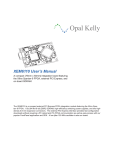
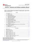
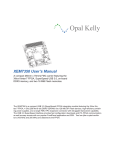
Opal Kelly
EVB100x User’s Manual
A 5-Mpixel image capture board for the XEM6010,
XEM6110, XEM3050, XEM3010, and Shuttle LX1
FPGA integration modules
The EVB1005 is an image capture module for use with the Opal Kelly XEM6010, XEM6110, XEM3050,
and XEM3010 FPGA modules. The EVB1006 is an equivalent capture module for the Shuttle LX1
(XEM6006) or other FMC carrier. Both modules include a Micron MT9P031I12STC 5 mega-pixel color
image sensor and necessary power supply circuitry. Designed as evaluation boards for Opal Kelly
integration modules, the modules provide an excellent platform for getting accustomed to the FrontPanel
SDK.
Software, documentation, samples, and related materials are
Copyright © 2011-2012 Opal Kelly Incorporated.
Opal Kelly Incorporated
Portland, Oregon
http://www.opalkelly.com
All rights reserved. Unauthorized duplication, in whole or part, of this document by any means except for brief
excerpts in published reviews is prohibited without the express written permission of Opal Kelly Incorporated.
Opal Kelly, the Opal Kelly Logo, and FrontPanel are trademarks of Opal Kelly Incorporated.
Linux is a registered trademark of Linus Torvalds. Microsoft and Windows are both registered trademarks of
Microsoft Corporation. All other trademarks referenced herein are the property of their respective owners and no
trademark rights to the same are claimed.
Revision History:
Date
Description
20120101
Initial release.
20121112
Fix EVB1006 Schematic with production version.
Contents
Introducing the EVB100x. . . . . . . . . . . . . . . . . . . . . . . . 5
Image Sensor. . . . . . . . . . . . . . . . . . . . . . . . . . . . . . . . . . . . . 5
Mechanical Information. . . . . . . . . . . . . . . . . . . . . . . . . . . . . . 5
Lens and Lens Holder (included with EVB100x) . . . . . . . 6
Functional Block Diagram. . . . . . . . . . . . . . . . . . . . . . . . . . . . 6
Power Supply. . . . . . . . . . . . . . . . . . . . . . . . . . . . . . . . . . . . . 6
XEM6110 . . . . . . . . . . . . . . . . . . . . . . . . . . . . . . . . . . . . . 6
XEM6010, XEM3050, and XEM3010. . . . . . . . . . . . . . . . 6
XEM6006. . . . . . . . . . . . . . . . . . . . . . . . . . . . . . . . . . . . . 7
JTAG Chain. . . . . . . . . . . . . . . . . . . . . . . . . . . . . . . . . . . . . . . 7
XEM6010 and XEM6110 . . . . . . . . . . . . . . . . . . . . . . . . . 7
XEM3010 and XEM3050. . . . . . . . . . . . . . . . . . . . . . . . . 7
Electrical Interfaces (EVB1005). . . . . . . . . . . . . . . . . . . . . . . 7
I2C Interface. . . . . . . . . . . . . . . . . . . . . . . . . . . . . . . . . . . 7
Pixel Interface. . . . . . . . . . . . . . . . . . . . . . . . . . . . . . . . . . 8
Electrical Interfaces (EVB1006). . . . . . . . . . . . . . . . . . . . . . . 8
I2C Interface. . . . . . . . . . . . . . . . . . . . . . . . . . . . . . . . . . . 8
Pixel Interface. . . . . . . . . . . . . . . . . . . . . . . . . . . . . . . . . . 8
Sensor to FPGA Pin Mapping. . . . . . . . . . . . . . . . . . . . . . . . . 8
Pin descriptions . . . . . . . . . . . . . . . . . . . . . . . . . . . . . . . . 9
Image Capture Processor Architecture. . . . . . . . . . . . . 11
Top-Level Architecture. . . . . . . . . . . . . . . . . . . . . . . . . . . . . . 12
Clock Management . . . . . . . . . . . . . . . . . . . . . . . . . . . . . 12
Reset Logic. . . . . . . . . . . . . . . . . . . . . . . . . . . . . . . . . . . . 12
Image Sensor Interface (ISI) . . . . . . . . . . . . . . . . . . . . . . 13
Host Interface. . . . . . . . . . . . . . . . . . . . . . . . . . . . . . . . . . 13
Memory Interface. . . . . . . . . . . . . . . . . . . . . . . . . . . . . . . 14
Ping-Pong Coordinator (PPC) . . . . . . . . . . . . . . . . . . . . . 14
I2C Controller . . . . . . . . . . . . . . . . . . . . . . . . . . . . . . . . . . 14
Aptina Sensor Notes. . . . . . . . . . . . . . . . . . . . . . . . . . . . . . . . 14
Data Valid Window. . . . . . . . . . . . . . . . . . . . . . . . . . . . . . 14
Line Valid and Frame Valid at High Clock Rates. . . . . . . 14
Software Host Interface . . . . . . . . . . . . . . . . . . . . . . . . . . . . . 15
Asynchronous Ports (Wire In / Wire Out). . . . . . . . . . . . . 15
Synchronous Trigger Ports (Trigger In / Trigger Out). . . . 16
Synchronous Data Transfer Port . . . . . . . . . . . . . . . . . . . 16
Host Software . . . . . . . . . . . . . . . . . . . . . . . . . . . . . . . . 17
okCCamera C++ Class. . . . . . . . . . . . . . . . . . . . . . . . . . . . . . 17
Image Capture Processor Initialization . . . . . . . . . . . . . . 17
Image Capture and Data Transfer . . . . . . . . . . . . . . . . . . 17
okSnap Command Line Application. . . . . . . . . . . . . . . . . . . . 18
Command Line Usage. . . . . . . . . . . . . . . . . . . . . . . . . . . 18
okCamera GUI Application. . . . . . . . . . . . . . . . . . . . . . . . . . . 18
wxWidgets . . . . . . . . . . . . . . . . . . . . . . . . . . . . . . . . . . . . 18
Threaded FrontPanel API Communication. . . . . . . . . . . . 18
FreeMat 3rd-Party Software Sample. . . . . . . . . . . . . . . . . . . 18
EVB100x User’s Manual
FrontPanel API Support. . . . . . . . . . . . . . . . . . . . . . . . . . 19
Interfacing to the Image Capture Processor . . . . . . . . . . 19
Data Manipulation and Image Display. . . . . . . . . . . . . . . 19
EVB1005 Schematic. . . . . . . . . . . . . . . . . . . . . . . . . . . 22
EVB1005 Mechanical Drawing . . . . . . . . . . . . . . . . . . . 23
EVB1006 Schematic. . . . . . . . . . . . . . . . . . . . . . . . . . . 24
EVB1006 Mechanical Drawing . . . . . . . . . . . . . . . . . . . 25
4
www.opalkelly.com
EVB100x User’s Manual
Introducing the EVB100x
The EVB1005 is an image capture module for use with the Opal Kelly XEM6010, XEM6110,
XEM3050, and XEM3010 FPGA modules. The EVB1006 is a similar capture module for the
Shuttle LX1 (XEM6006) or other FMC carrier. Both modules include a Micron MT9P031I12STC
5 mega-pixel color image sensor and necessary power supply circuitry. Designed as evaluation
boards for Opal Kelly integration modules, the modules provide an excellent platform for getting
accustomed to the FrontPanel SDK in a demanding, real-world application.
Image Sensor
The heart of the EVB100x is a Micron MT9P031I12STC with the following features and specifications:
•
•
•
•
•
•
1/2.5-inch, 5-Megapixel CMOS digital image sensor, 12-bit ADC resolution
Active pixel array of 2592H x 1944V
RGB Bayer color filter array
Snapshot and Electronic rolling shutter
96 Mp/s readout rate
Full resolution frame rate to 14 fps. VGA frame rate to 53 fps.
Mechanical Information
The EVB1005 is designed to mate directly with the expansion bus on the XEM6010 and similar
devices. The dimensions of the board are identical to those of the XEM6010 so that the mating
is natural and the combination can easily be handled. The EVB1006 is a standard FMC device
and is compatible with our Shuttle LX1 and most other FMC carriers.
www.opalkelly.com
5
EVB100x User’s Manual
Mechanical drawings of the two modules are at the end of this document.
Lens and Lens Holder (included with EVB100x)
A high-quality glass lens, plastic lens holder, and mounting hardware are included with the
EVB1005. The part and supplier information is listed below. Sunex also has a higher-quality
lens available with better optics, the DSL944.
Part
Description
Supplier
CMT821
Lens Holder
Sunex (www.optics-online.com)
DSL853C-650
Glass Lens
Sunex (www.optics-online.com)
92005A006
Screw M1.6, 8mm, pan-head
McMaster-Carr
90591A109
Hex nut, M1.6, 0.35mm
McMaster-Carr
Functional Block Diagram
EXTCLK, RESET, TRIGGER
(EVB1005-only)
XEM
CPLD
(XA2C32A)
CLK, PIX[11:0],
FV, LV, STROBE
Micron
Image Sensor
(MT9P031)
(EVB1005-only)
MAX3378
SCL+SDA
Power Supply
The EVB100x provides +2.8-v and +1.8-v using linear regulators from the +VDC power supply.
+2.8-v is used to power the image sensor’s internal analog circuitry as well as the I/O components. The +1.8-v is used to power the image sensor’s internal digital circuitry and the CPLD.
XEM6110
When attached to the XEM6110 (which does not have a power connector), the +VDC supply is
provided to the EVB1005 through the barrel connector. It must be within the range +4.5-v and
+5.5-v. The center conductor is power. The ring conductor is ground.
+VDC is then provided through the expansion connector to the XEM6110.
XEM6010, XEM3050, and XEM3010
When attached to the XEM6010, XEM3050, or XEM3010, the +VDC supply is provided to the
EVB1005 through the expansion connector. The external power supply may be connected to
either the EVB1005 or the XEM, but only one supply should be attached at a time.
6
www.opalkelly.com
EVB100x User’s Manual
XEM6006
The EVB1006 derives power from the FMC connector on the XEM6006. A power connector is
not available on the EVB1006.
JTAG Chain
The EVB1005 has a 14-pin connector (JP3) which is compatible with the Xilinx Platform USB
JTAG connector to allow JTAG programming of the CPLD as well as JTAG communication with
the FPGA for ChipScope.
XEM6010 and XEM6110
The JTAG chain when used with the XEM6010 and XEM6110 is shown in the diagram below.
The Xilinx JTAG adapter is attached to the EVB1005 and both the CPLD on the EVB1005 and
the FPGA are part of the chain.
JP3
Xilinx
JTAG
Cable
TDO
TDI
JP1
EVB1005
XEM6x10
CPLD
FPGA
TDI
TDO
TDI
TDO
XEM3010 and XEM3050
The JTAG chain is not configured to be used with the XEM3010 or XEM3050.
Electrical Interfaces (EVB1005)
The EVB1005 was designed to operate with the default 3.3-volt I/O on the XEM6010 and
XEM6110 devices. Although both devices allow a daughterboard to set the VCCIO on each
bank, this requires removal of a ferrite bead on the FPGA module. To avoid this modification,
voltage level translation is used instead.
The Micron image sensor digital I/O voltage can also be set to 1.8-v or 2.8-v, but even at the 2.8volt level, the Output HIGH voltage is below the Input HIGH threshold of the Spartan-6 FPGA.
I2C Interface
The image sensor uses an I2C interface for reading and writing several control registers that
command the operation of the sensor, set acquisition gains and offsets, and determine how pixel
readout is performed.
The HDL design will require a simple I2C controller to communicate with this interface. A Maxim
MAX3378EEUD+ is installed to perform the bidirectional level translation require for I2C interfaces.
www.opalkelly.com
7
EVB100x User’s Manual
Pixel Interface
The Micron sensor is set to use 2.8-volts for VDDIO. In this configuration, the unidirectional
signals from the FPGA to the image sensor (EXTCLK, RESET, and TRIGGER) may be sent directly
without level translation.
The unidirectional signals from the image sensor to the FPGA, however, go through a Xilinx
CoolRunner II CPLD for level translation. The bank facing the image sensor is set to +2.8-v. The
bank facing the FPGA is set to +VCCO, the FPGA’s bank voltage (+3.3v).
The CPLD programming files are included assets with the EVB100x Developer’s Release.
Electrical Interfaces (EVB1006)
The EVB1006 is an FMC device and contains an EEPROM with IPMI configuration data that
configures the FMC carrier for the proper interface voltages. Due to this electrical definition of
the interface voltage, no jumpers or ferrite beads need to be manipulated.
I2C Interface
The image sensor uses an I2C interface for reading and writing several control registers that
command the operation of the sensor, set acquisition gains and offsets, and determine how pixel
readout is performed.
The HDL design will require a simple I2C controller to communicate with this interface. A Maxim
MAX3378EEUD+ is installed to perform the bidirectional level translation required for I2C interfaces.
Pixel Interface
The Micron sensor is set to use 2.8-volts for VDDIO. The FMC interface is configured to a 2.5-v
I/O voltage compatible with the Spartan-6 FPGA. In this configuration, the unidirectional signals
from the FPGA to the image sensor (EXTCLK, RESET, and TRIGGER) may be sent directly without
level translation and will satisfy the sensor’s input thresholds. Similarly, the image sensor outputs
may be sent directly to the FPGA without level translation. The higher output voltage is below the
recommended operating input voltage for the Spartan-6 and will not cause damage.
Sensor to FPGA Pin Mapping
The table below lists the pin mapping from the sensor to the FPGA on the XEM6010, XEM6110,
XEM3010, XEM3050, and XEM6006 (EVB1006).
8
www.opalkelly.com
EVB100x User’s Manual
Sensor
Direction
XEM6010 / XEM6110
XEM3010
XEM3050
XEM6006
EXTCLK
O
A11
F9
B13
C10
RESET
O
A15
D1
H3
E7
TRIGGER
O
C15
E2
H4
E8
SCLK
O
A13
E1
J2
A14
SDATA
I/O
C13
F2
J3
F10
STROBE
I
A7
H3
L1
D11
PIXCLK
I
C11
E9
A13
E10
LV
I
A6
G5
M1
D12
FV
I
C7
F5
L2
B14
PIX0
I
A18
B1
E4
A9
PIX1
I
A17
C1
E1
B8
PIX2
I
C17
D2
E2
C9
PIX3
I
B18
C3
E3
A11
PIX4
I
A16
C2
D1
A10
PIX5
I
B16
D3
D2
A13
PIX6
I
A14
E4
G1
C11
PIX7
I
B14
E3
G2
B10
PIX8
I
A12
F4
H1
D9
PIX9
I
B12
G4
H2
C13
PIX10
I
A9
G3
K3
F9
PIX11
I
C9
H4
K4
E11
Pin descriptions
EXTCLK - Output clock to the image sensor.
RESET - Output reset signal to the image sensor. Active low.
TRIGGER - Trigger signal to the image sensor.
SCLK / SDATA - I2C control interface to the image sensor.
STROBE - Input from the image sensor
PIXCLK - Input clock from the image sensor. This is sent with data as “source-synchronous”
and is the clock that should be used when capturing the incoming sensor data.
FV - Image frame-valid signal from the image sensor.
LV - Image line-valid signal from the image sensor.
PIX[11:0] - 12-bit pixel data from the image sensor.
For detailed information on these signals, please refer to the Micron MT9P031 data sheet.
www.opalkelly.com
9
EVB100x User’s Manual
10
www.opalkelly.com
EVB100x User’s Manual
Image Capture Processor Architecture
The EVB100x includes FPGA logic which performs the function of an image capture processor (ICP). This logic is designed with Opal Kelly’s FrontPanel HDL so it may communicate with
software using the FrontPanel API. This section describes the architecture of the ICP so that you
may use it in your own applications. Of course, more advanced processing is possible with your
own logic processor.
There are a number of ways to apply the FrontPanel API and HDL to achieve image capture and
processing with a given image sensor. This ICP is just one example architecture. Others may
be more efficient depending on the specific requirements at hand. The architecture description
below is not intended to be complete documentation for the ICP -- just an overview of its design.
For further detail, please see the source code.
www.opalkelly.com
11
EVB100x User’s Manual
Top-Level Architecture
CLK_PIX
CLK, PIX[11:0],
FV, LV, STROBE
CLK_SYS
WRITE I/F
Image
I/F
Memory
Controller
CMD I/F
start_addr
Ping-Pong
Coordinator
CLK_TI
READ I/F
okPipeOut
FIFO
CMD I/F
Host
I/F
readout_start
readout_done
readout_addr[30:0]
buffer_full[1:0]
readout_count[23:0]
okTriggerIn
okTriggerIn
okWireIn
okWireIn
FrontPanel
Host
Interface
okWireOut
okTriggerIn
trigger
okTriggerOut
frame_done
okWireIn
packing_mode
SCL
IC
Controller
2
SDA
I2C I/F
okWire /
okTrigger)
Clock Management
At FPGA configuration, the following clocks are available to the design:
CLK _ TI - This is the target interface clock from the FrontPanel okHost. This clock is 48
MHz for USB 2.0 hosts. It is typically locked with a DCM in the okLibrary source for
okHost and is available on one of the FPGA’s clock networks.
CLK _ SYS - This is a 100 MHz clock input on the XEM3010, XEM3050, XEM6010, and
XEM6110. On the first three, it is provided by the on-board PLL. On the XEM6110, it is
provided by the on-board clock oscillator. This signal is not avaialble on the Shuttle LX1
(XEM6006).
CLK _ PIX - This is the clock signal received from the image sensor and synchronized by a
DCM in the FPGA. CLK _ PIX is then used for all pixel-clock logic in the design.
After the FPGA is configured, it outputs PIX _ EXTCLK to the image sensor. The frequency of
this signal varies depending on the FPGA module. On the XEM6006, it is 24 MHz. On all other
modules, it is 25 MHz. The image sensor has an on-chip PLL which is configured by the camera initialization sequence to output a pixel clock of 96 MHz. This clock is then received by the
FPGA as CLK _ PIX.
The general clock domain organization can be seen in the top-level architecture block diagram
above. The clock domains are shaded behind the various blocks represented on that domain.
Reset Logic
Multiple reset signals are delivered to the ICP from the host interface. All resets are asserted
high. These are:
RESET _ SYSPLL - Resets the overall system PLL
RESET _ SENSOR - Reset the image sensor
12
www.opalkelly.com
EVB100x User’s Manual
RESET _ PIXDCM - Resets the DCM used to synchronize to the pixel clock
RESET _ LOGIC - Reset all state machines and ICP logic
The logic reset (RESET _ LOGIC) is an asynchronous reset to the ICP. From this asynchronous
reset, the ICP generates clock-domain-specific resets which assert asynchronously and deassert
synchronously with the corresponding clock domain. These are:
RESET _ CLKPIX - Deassertion synchronous to CLK _ PIX
RESET _ CLK0 - Deassertion synchronous to CLK0
RESET _ CLKTI - Deassertion synchronous to CLK _ TI
Image Sensor Interface (ISI)
The image sensor interface (image _ if.v) has a small state machine that observes the incoming image stream (PIX _ FV, PIX _ LV, and PIXDATA) and generates control signals for the
memory interface. No FIFO or other buffering is required because the image sensor interface
makes use of the buffering already present in the memory interface.
The state machine has a configuration input (PACKING _ MODE) which specifies how incoming
image data is packed into memory:
8-BPP - When PACKING _ MODE=0, the eight most-significant bits of each 12-bit pixel are
packed into the words written to memory. The least-significant bits are discarded. Since
the memory interface is 64-bits wide, a memory word is written every eight pixel clocks.
16-BPP - When PACKING _ MODE=1, each 12-bit pixel is padded with 0’s to a 16-bit word
and packed into the words written to memory. A memory word is written every four pixel
clocks.
At the end of a frame, the memory interface is commanded to write another burst to memory.
This effectively flushes the memory interface write buffer in case additional pixels were written to
the buffer but it did not completely fill to the burst size.
Host Interface
The host interface (host _ if.v) interfaces the memory interface to the Opal Kelly FrontPanel
PipeOut HDL module to transfer image data back to the host. This is a one-way communication
and crosses a clock boundary with CLK _ SYS on one side and CLK _ TI on the other. A small
block memory FIFO is used to cross this boundary.
The state machine in the host interface sits IDLE until a readout is initiated by the host. Once
initiated, the host interface captures the readout start address (READOUT _ ADDR[29:0]) and the
readout byte count (READOUT _ COUNT[23:0]). It then successively issues memory read commands as long as there is space available in the FIFO until the full readout count has been read.
The host will be reading from this FIFO.
Because the memory interface can easily keep pace with the host reads, no additional throttling
is required. The FIFO is reset at the beginning of each readout to make sure it is empty prior to a
readout.
www.opalkelly.com
13
EVB100x User’s Manual
Memory Interface
The memory interface is generated by the Xilinx Core Generator / Memory Interface Generator
(MIG). For the Spartan-6 FPGA, this utilizes the hard-core memory controller block and consumes very little additional fabric resources. The MIG is configurable to support a number of
different interface ports. For our purposes, we only use two ports: one for writing to the memory
from the image sensor interface and one for reading from the memory to the host interface.
MIG ports each have their own read and write clock domains. Operations are performed by writing commands to a command FIFO on each port. Complete documentation on the operation of
the memory interface is available from Xilinx.
Ping-Pong Coordinator (PPC)
The Ping-Pong Coordinator is a simple state machine that is used when the ICP is placed in
ping-pong mode and performs continuous image capture. In this mode, memory is segmented
into two separate buffers so that one may be read out by the host while the other is being written to by the image sensor interface. The PPC becomes the commanding process for the image
sensor interface and dictates when image capture should proceed and which buffer should be
utilized.
The PPC maintains two flags (BUFFER _ FULL[1:0]) that are set when a buffer is writen by the
ISI. When the host completes readout of one of these buffers, the corresponding flag is then
cleared by the PPC and may be written again.
I2C Controller
In order to communicate with the image sensor’s register interface and configure the sensor,
a simple I2C controller is provided. This controller is commanded through the FrontPanel host
interface using only Wires and Triggers.
Source code for the I2C controller is not provided.
Aptina Sensor Notes
At the time this documentation was written, the MT9P031 datasheet was published at Ref. F
dated May 2011. There are a few notes and errata that should be mentioned. Aptina application
support was very helpful in resolving these issues.
Data Valid Window
Figure 29 of the datasheet represents the I/O Timing Diagram. According to Aptina, the correct
way to interpret Tpd from this diagram and the timing characteristics is that data is valid as early
as 0.8ns before the rising edge of PIXCLK. So the minimum time should probably be written as
-0.8ns.
This modified timing is reflected in the constraints files provided in the Developer’s Release.
Line Valid and Frame Valid at High Clock Rates
Pixel data, LV, and FV are launched from the sensor on the rising edge of PIXCLK and Aptina
suggests capturing these on the falling edge. However, the maximum time from PIXCLK (rising
edge) to LV and FV becoming valid is 5.9ns. At 96 MHz pixel rates, the clock period is 10.4ns.
Therefore, these transitions would occur after the falling edge. This causes synchronization problems.
14
www.opalkelly.com
EVB100x User’s Manual
Aptina has released Technical Note TN-09-148 that addresses this issue. Their recommendation
is to run the image sensor at 96 MHz, but enable an undocumented internal FIFO to allow pixel
data to be read out during the horizontal blanking period. This makes the internal sensor clock
run at 96 MHz, but the PIXCLK and data outputs are run at 72 MHz. Our software configures the
image sensor according to this technical note.
Software Host Interface
Asynchronous Ports (Wire In / Wire Out)
The following are asynchronous inputs and outputs to the ICP. They are provided via WireIn /
WireOut HDL modules and are re-timed to individual state machine clock domains as necessary.
Register
WI[00|0]
Signal
Description
WI[00|2]
RESET_SYSPLL
System PLL reset (active high)
WI[00|1]
PIX_RESET
Image sensor reset (active high)
RESET_PIXDCM
PIXCLK DCM reset (active high)
WI[00|3]
RESET_ASYNC
Asynchronous logic reset
WI[00|4]
-
Capture mode (0:Trigger, 1:Ping-pong)
WI[00|5]
-
Image packing (0:8-bit, 1:16-bit)
WI[01|7:0]
I2C_MEMDIN
I2C controller input data
WI[02|15:0]
READOUT_COUNT_L
Image readout count (least-significant word)
WI[03|15:0]
READOUT_COUNT_H
Image readout count (most-significant word)
WI[04|15:0]
READOUT_ADDR_L
Image readout address (least-significant word)
WI[05|15:0]
READOUT_ADDR_H
Image readout address (most-significant word)
WI[20|10:0]
PIPE_OUT_RD_COUNT
Image readout count
WI[22|7:0]
I2C_MEMDOUT
I2C controller output data
WI[23|7:0]
SKIPPED_COUNT
Skipped image count (ping-pong mode only)
WI[23|9:8]
BUFFER_FULL
Buffer status for ping-pong buffers
www.opalkelly.com
15
EVB100x User’s Manual
Synchronous Trigger Ports (Trigger In / Trigger Out)
The following are synchronous trigger ports that are established on specific clock domains within
the ICP. They perform “event-based” communication with the PC over FrontPanel TriggerIn / TriggerOut HDL endpoints.
Register
TI[40|0]
Clock Domain
Description
TI[40|2]
CLK_PIX
Triggers a single image capture
TI[40|1]
CLK_TI
Signals the beginning of image readout
CLK_SYS
Signals completion of image readout from buffer A
TI[40|3]
CLK_SYS
Signals completion of image readout from buffer B
TI[42|0]
CLK_TI
Initiates an I2C operation
TI[42|1]
CLK_TI
I2C memory pointer reset
TI[42|2]
CLK_TI
I2C memory write
TI[42|3]
CLK_TI
I2C memory read
TO[60|0]
CLK_PIX
Frame available
TO[61|0]
CLK_TI
I2C operation done
Synchronous Data Transfer Port
PipeOut port 0xA0 is the only synchronous data transfer port utilized. It is used to read out image
data after an acquisition.
16
www.opalkelly.com
EVB100x User’s Manual
Host Software
okCCamera C++ Class
We have wrapped the basic functionality of the camera into a lightweight C++ class which should
serves as the only interface to the device. The okCCamera object should handle all communication with the device via the FrontPanel API. Both the okSnap command-line application and the
okCamera GUI application make use of this common class to communicate with the camera.
Image Capture Processor Initialization
Initializing the camera for operation involves the following sequence:
1. Create an instance of okCFrontPanel
2. Open a device
3. Configure the PLL (for boards with an on-board PLL)
4. Configure the FPGA with the appropriate bitfile
5. Perform logic reset as required
These five steps are performed by the Initialize() method. Until this method is called successfully, the camera remains in an uninitialized state and cannot be used.
Image Capture and Data Transfer
A single image capture cycle is initiated and read using the method SingleCapture(). This
method performs the following sequence:
1. Sets the image length to the READOUT_COUNT register.
2. Sets READOUT _ ADDRESS to 0x00000000.
www.opalkelly.com
17
EVB100x User’s Manual
3. Triggers the capture
4. Waits until the frame done trigger
5. Triggers readout start
6. Reads the complete image data
7. Triggers readout done
okSnap Command Line Application
okSnap is setup to be a very simple command-line application that connects to the camera, configures the image sensor and image capture processor, then retrieves a single image with some
default settings. It is not intended to be a full-featured application but highlights the primary interface capabilities required to talk to the camera. Using okSnap as a starting point, it is possible to
expand to a more capable command-line interface.
Command Line Usage
okSnap takes two arguments. The first is the image sensor acquisition mode taken from the
MT9P031 datasheet. “0” means normal image acquisition. “9” is a diagonal gradient. The gradient and other test modes are useful for ICP testing.
> okSnap 0 image.bin
The resulting output file (image.bin) will be the full image acquisition output from the sensor.
okCamera GUI Application
wxWidgets
The okCamera application is built using the wxWidgets cross-platform C++ GUI class library.
More information may be found at the following site:
http://www.wxwidgets.org
Threaded FrontPanel API Communication
To create a well-behaved GUI application, it is important that any long-running processing be
performed in a separate thread from the application’s GUI thread. In the case of okCamera,
certain operations such as image readout can take a while. Therefore, we have moved all camera communication (and, in effect, all communication over the FrontPanel API) into a separate
thread. This thread is abstracted in the okCThreadCamera class and represents a disciplined
method of device communication.
FreeMat 3rd-Party Software Sample
FreeMat is an open-source development environment, similar to MATLAB, designed for rapid
engineering, scientific prototyping, and data processing. It has extensive script capabilities for
processing vector and matrix data (such as images) and also has the capability to interface with
external (3rd-party) interfaces such as the Opal Kelly FrontPanel API. Together, these features
make it an attractive platform for a sample interface to the EVB100x.
More information about FreeMat may be found here:
18
www.opalkelly.com
EVB100x User’s Manual
http://freemat.sourceforge.net/
FrontPanel API Support
Basic FrontPanel API support has been imported into FreeMat using the import command
which creates FreeMat commands from DLL entry-points. In some cases, the preferred functional representation of the API command is not directly available with this method. For example,
GetDeviceSerialNumber returns a string. FreeMat needs to be called with an empty string of
the proper length in order to use this direct import.
The preferred functionality could be accomplished with a separately-defined FreeMat command
that wraps the imported DLL command. For simplicity, we simply work around these deficiencies
in the example code. To a great extent, a one-to-one mapping of the API commands has been
accomplished. The exceptions are simple to deal with and understand.
Interfacing to the Image Capture Processor
Initial configuration and setup for the camera is easy using the imported FrontPanel methods:
dev = okFPConstruct;
okFPOpenBySerialX(dev, 0);
okFPLoadDefaultPLLConfiguration(dev);
okFPConfigureFPGA(dev, ‘evb1005-xem6010-lx45.bit’);
% Reset
okCameraFullReset(dev);
The okCameraFullReset function is defined using API methods as well:
function okCameraFullReset(dev)
okFPSetWireInValue(dev, hex2dec(‘00’), hex2dec(‘000f’), hex2dec(‘000f’));
okFPUpdateWireIns(dev);
okFPSetWireInValue(dev, hex2dec(‘00’), hex2dec(‘0000’), hex2dec(‘0001’));
okFPUpdateWireIns(dev);
...
% REG_PLL_CONTROL = 0x0051
okCameraI2CWrite(dev, hex2dec(‘10’), hex2dec(‘0051’));
% For the XEM6010 / EVB1005
N=5; M=72; P1=3;
% REG_PLL_CONFIG1 = ((N-1)<<0) | (M<<8)
okCameraI2CWrite(dev, hex2dec(‘11’), N-1 + M*256);
% REG_PLL_CONFIG2 = (P1-1)<<0
okCameraI2CWrite(dev, hex2dec(‘12’), P1-1);
...
okCameraLogicReset(dev);
Data Manipulation and Image Display
The captured image data is received as a 5 megabyte uint8 vector which is packed one byte
per pixel. To format for display using FreeMat’s image command, the vector is manipulated into
a 1296 x 944 x 3 array where each plane of the array represents the red, green, and blue pixels
from the Bayer pattern. For simplicity, the pattern is decimated to fit the array dimension. Much
more could be done to perform higher-quality demosaicing of the image.
www.opalkelly.com
19
EVB100x User’s Manual
% Read the captured image
okFPReadFromPipeOut(dev, hex2dec(‘a0’), imglen, imgdata);
% Format for image() display
tmp = double(reshape(img(1:x*y), x, y)).’;
imgv = zeros(y/2, x/2, 3);
imgv(:,:,1) = tmp(1:2:y, 2:2:x)/256; % RED
imgv(:,:,2) = tmp(1:2:y, 1:2:x)/256; % GREEN
imgv(:,:,3) = tmp(2:2:y, 1:2:x)/256; % BLUE
image(img);
20
www.opalkelly.com
EVB100x User’s Manual
www.opalkelly.com
21
D
C
B
DGND
1
+2.8VAA
DGND
+2.8VAA
DGND
+2.8VAA
C20
0.01 u
C12
0.01 u
7
26
C8
0.01 u
DGND
3
20
21
6
16
14
17
15
FPGA_RESET
FPGA_TRIGGER
31
FPGA_EXTCLK
R3
10 k
+2.8VAA
4
5
13
C9
0.1 u
VCCIO1 VAUX
VCCIO2
VCC
EXTCLK
DGND
TEST
TEST
TEST
RSVD
RESET
STANDBY
OE
TRIGGER
35
15
C21
0.1 u
C18
0.1 u
C13
0.1 u
2
DOUT0
DOUT1
DOUT2
DOUT3
DOUT4
DOUT5
DOUT6
DOUT7
DOUT8
DOUT9
DOUT10
DOUT11
FRAME_VALID
LINE_VALID
STROBE
PIX_CLK
IMG_PIXCLK
IMG_FV
IMG_LV
IMG_STROBE
IMG_PIX0
IMG_PIX1
IMG_PIX2
IMG_PIX3
IMG_PIX4
IMG_PIX5
IMG_PIX6
IMG_PIX7
IMG_PIX8
IMG_PIX9
IMG_PIX10
IMG_PIX11
7
8
9
33
34
35
36
37
38
40
41
42
43
44
45
C16
0.01 u
32
C14
0.1 u
FPGA_PIXCLK
FPGA_PIX0
FPGA_PIX1
FPGA_PIX2
FPGA_PIX3
FPGA_PIX4
FPGA_PIX5
FPGA_PIX6
FPGA_PIX7
FPGA_PIX8
FPGA_PIX9
FPGA_PIX10
FPGA_PIX11
FPGA_STROBE
FPGA_FV
FPGA_LV
DGND
+1.8VDD
DGND
+3.3VDD
2
U1
MT9P031
U4B
XC2C32A-6VQG44C
19
I/O
20
I/O
21
I/O
22
I/O
23
I/O
27
I/O
28
I/O
29
I/O
30
I/O, GSR
31
I/O, GTS2
32
I/O, GTS3
33
I/O, GTS0
34
I/O, GTS1
36
I/O
37
I/O
38
I/O
U4E
XC2C32A-6VQG44C
SCLK
SDATA
SADDR
C10
0.1 u
U4A
XC2C32A-6VQG44C
39
I/O
40
I/O
41
I/O
42
I/O
43
I/O, GCK0
44
I/O, GCK1
1
I/O, GCK2
2
I/O
3
I/O
5
I/O
6
I/O
8
I/O
12
I/O
13
I/O
14
I/O
16
I/O
C19
0.1 u
IMG_SCLK
IMG_SDATA
C7
0.01 u
IMG_PIX11
IMG_PIX6
IMG_PIX7
IMG_PIX8
IMG_PIX10
IMG_PIX9
IMG_PIXCLK
IMG_PIX5
IMG_PIX4
IMG_PIX3
IMG_PIX2
IMG_PIX1
IMG_PIX0
IMG_FV
IMG_LV
IMG_STROBE
DGND
+VCCO
C11
0.1 u
BANK 1
+2.8VAA
BANK 2
A
23
24
1
48
25
VAA
VAA
VAA_PIX
VAA_PIX
VDD_PLL
AGND
AGND
2
22
12
47
VDD
VDD
11
39
VDDIO
VDDIO
DGND
DGND
DGND
10
26
46
C17
0.01 u
DGND
+1.8VDD
DGND
DGND
+VDC
+VDC
+VDC
DGND
+VCCO
C22
0.1 u
1
3
5
7
9
11
13
15
17
19
21
23
25
27
29
31
33
35
37
39
41
43
45
47
49
51
53
55
57
59
61
63
65
67
69
71
73
75
77
79
3
R8
2.2 k
5
NoLoad
2
4
6
8
10
12
14
16
18
20
22
24
26
28
30
32
34
36
38
40
42
44
46
48
50
52
54
56
58
60
62
64
66
68
70
72
74
76
78
80
FPGA_SDATA
FPGA_SCLK
FPGA_SDATA
FPGA_SCLK
FPGA_TRIGGER
FPGA_RESET
FPGA_PIX2
FPGA_PIX1
FPGA_PIX0
FPGA_PIXCLK
FPGA_EXTCLK
3
DGND
DGND
+VDC
+VDC
DGND
DGND
DGND
R9
2.2 k
5
NoLoad
DGND
DGND
+VCCO
C4
1.0 u
10
C1
1.0 u
10
7
10
11
12
13
14
18
9
24
11
10
25
17
GND
3
1
3
1
VL
THREESTATE
I/O VL4
I/O VL3
I/O VL2
I/O VL1
Input
VOUT
DGND
NR/FB
EN
VIN
DGND
NR/FB
VOUT
U2
TPS73201DBVT
EN
VIN
8
5
4
3
2
1
4
5
4
5
U4C
XC2C32A-6VQG44C
TDI
TDO
TCK
TMS
U4D
XC2C32A-6VQG44C
U3
TPS73201DBVT
I/O VCC4
I/O VCC3
I/O VCC2
I/O VCC1
VCC
DGND
U4F
XC2C32A-6VQG44C
4
GND
GND
GND
U5
MAX3378EEUD+
JTAG_TDI
CPLD_TDO
JTAG_TCK
JTAG_TMS
DGND
FPGA_STROBE
FPGA_PIX11
FPGA_PIX10
FPGA_PIX9
FPGA_PIX8
FPGA_PIX7
FPGA_PIX6
FPGA_PIX5
FPGA_PIX4
FPGA_PIX3
+VCCO
Design Note: Keep All I/O on
VCCO0 for consistency.
FOCUS_SCL
FOCUS_SDA
FOCUS_SDI
FOCUS_SDO
FOCUS_SCK
FOCUS_SS
FOCUS_RST
FPGA_LV
FPGA_FV
JP2
BTE-040-01-F-D-A
GND
2
www.opalkelly.com
GND
22
2
1
C5
0.01 u
C2
0.01 u
+2.8VAA
R10
2.2 k
5
NoLoad
DGND
FPGA_TCK
FPGA_TMS
FPGA_TDI
4
4
R7
56.2 k
1
R6
28.0 k
1
R5
33.2 k
1
R4
44.2 k
1
R11
2.2 k
5
NoLoad
1
3
5
7
9
11
13
15
17
19
21
23
25
27
29
31
33
35
37
39
41
43
45
47
49
51
53
55
57
59
61
63
65
67
69
71
73
75
77
79
C23
0.1 u
C6
0.1 u
C3
0.1 u
+1.8VDD
+2.8VAA
IMG_SDATA
DGND
+2.8VAA
FPGA_TDO
IMG_SCLK
2
4
6
8
10
12
14
16
18
20
22
24
26
28
30
32
34
36
38
40
42
44
46
48
50
52
54
56
58
60
62
64
66
68
70
72
74
76
78
80
JP1
BTE-040-01-F-D-A
DGND
DGND
DGND
DGND
DGND
+3.3VDD
+3.3VDD
+3.3VDD
VREF
TMS
TCK
TDO
TDI
NC
NC
0
R14
0
R12
0
R2
0
R1
2
4
6
8
10
12
14
JTAG_TMS
JTAG_TCK
JTAG_TDO
JTAG_TDI
R13
0
NoLoad CPLD_TDO
JTAG_TDO
JTAG_TMS
JTAG_TCK
JTAGXLNX
GND
GND
GND
GND
GND
GND
GND
JP3
+3.3VDD
5
Time: 5:10:29 PM
Sheet 1
Revision: 2
of
1
Opal Kelly
13500 SW 72nd Ave, STE 120
Portland, OR 97223
http://www.opalkelly.com
FOCUS_RST
R17
4.7 k
5
5
9
10
FOCUS_SS
DGND
6
7
8
2
4
FOCUS_SDI
FOCUS_SDO
FOCUS_SCK
+VCCO
DGND
C24
100 p
R16
2.2 k
5
+VCCO
C15
100 p
DGND
Design Note: SS and RST
have a 10k pullup on the
M3-F put putting pullup on
RST to play it safe.
FOCUS_SCL
FOCUS_SDA
R15
2.2 k
5
+VCCO
XEM3010 JTAG:
+ JTAG_TDI > CPLD_TDI > CPLD_TDO > JTAG_TDO
+ FPGA_TDI and FPGA_TDO disconnected
+ JTAG continuity is not configured
XEM6010 JTAG (default):
+ JTAG_TDI > CPLD_TDI > CPLD_TDO > FPGA_TDI > FPGA_TDO > JTAG_TDO
+ VDD_JTAG == +3.3VDD
FPGA_TDI
FPGA_TDO
FPGA_TMS
FPGA_TCK
Number: xxx
EVB1005
Date: 12/1/2011
File:
Size: C
Title
Design Note: Vcco = 3.3V. It
must be >2.8V for U5 to work
correctly.
1
3
5
7
9
11
13
DGND
5
VSS
SS
RST
SDI
SDO
SCK
NC
MNT
6
TP4
TP3
TP2
TP1
P1
PJ-102AH
1
3
2
1
0
DGND
+1.8VDD
+2.8VAA
+VDC
+VCCO
DGND
+VDC
DGND
P2
FH12-10S-0.5SH(55)
3
SCL VDD
SDA
6
D
C
B
A
EVB100x User’s Manual
EVB1005 Schematic
EVB100x User’s Manual
72.00
75.00
60.48
42.74
0
3.00
8.27
10.70
13.00
15.30
23.00
EVB1005 Mechanical Drawing
50.00
47.04
50.00
47.00
42.33
35.00
33.33
25.00
24.39
15.00
14
3.00
0
.5
60
1.
7.03
67.26
72.00
75.00
42.74
0
0
3.00
8.27
0
0
2.5
50.00
45.01
0
50.00
37.83
0
6.5
0
14.60
12.80
12.60
8.10
7.80
6.80
1.57
0
25.50
4.99
0
All dimensions in mm
www.opalkelly.com
23
D
C
B
1
TP20
TP21
C6
C7
D4
D5
G6
G7
D8
D9
H7
H8
G9
G10
H10
H11
D11
D12
C10
C11
H13
H14
G12
G13
D14
D15
C14
C15
H16
H17
G15
G16
D17
D18
C18
C19
H19
H20
G18
G19
H4
H5
R2
2.2k
5%
+2.8VAA
IMG_PIXCLK
IMG_EXTCLK
IMG_RESET
IMG_TRIGGER
IMG_STROBE
IMG_LV
IMG_FV
IMG_SCLK
IMG_SDATA
IMG_PIX11
IMG_PIX9
IMG_PIX5
IMG_PIX10
IMG_PIX8
IMG_PIX6
IMG_PIX3
IMG_PIX7
IMG_PIX4
IMG_PIX2
IMG_PIX0
IMG_PIX1
Design Note: Use FX2 clk
48MHz x 2 = 96MHz.
2
R3
2.2k
5%
TP23
+2.8VAA
DGND
TP24
TP22
DGND
3
20
21
6
16
14
17
15
IMG_TRIGGER
IMG_RESET
4
5
13
C9
0.1 u
31
R9
10k
5%
+2.8VAA
IMG_SCLK
IMG_SDATA
C8
10 n
C2
C3
D20
D21
C22
C23
H22
H23
G21
G22
H25
H26
G24
G25
D23
D24
H28
H29
G27
G28
D26
D27
C26
C27
H31
H32
G30
G31
H34
H35
G33
G34
H37
H38
G36
G37
G2
G3
IMG_EXTCLK
C7
10 n
DP0_C2M_P
DP0_C2M_N
+2.8VAA
DGND
+2.8VAA
DP0_M2C_P
DP0_M2C_N
GBTCLK0_M2C_P
GBTCLK0_M2C_N
P1B
ASP-134604-01
LA00_P_CC LA17_P_CC
LA00_N_CC LA17_N_CC
LA01_P_CC LA18_P_CC
LA01_N_CC LA18_N_CC
LA02_P
LA19_P
LA02_N
LA19_N
LA03_P
LA20_P
LA03_N
LA20_N
LA04_P
LA21_P
LA04_N
LA21_N
LA05_P
LA22_P
LA05_N
LA22_N
LA06_P
LA23_P
LA06_N
LA23_N
LA07_P
LA24_P
LA07_N
LA24_N
LA08_P
LA25_P
LA08_N
LA25_N
LA09_P
LA26_P
LA09_N
LA26_N
LA10_P
LA27_P
LA10_N
LA27_N
LA11_P
LA28_P
LA11_N
LA28_N
LA12_P
LA29_P
LA12_N
LA29_N
LA13_P
LA30_P
LA13_N
LA30_N
LA14_P
LA31_P
LA14_N
LA31_N
LA15_P
LA32_P
LA15_N
LA32_N
LA16_P
LA33_P
LA16_N
LA33_N
CLK0_M2C_PCLK1_M2C_P
CLK0_M2C_N
CLK1_M2C_N
P1A
ASP-134604-01
2
DGND
TEST
TEST
TEST
RSVD
RESET
STANDBY
OE
TRIGGER
EXTCLK
SCLK
SDATA
SADDR
C10
0.1 u
23
24
1
48
25
VAA
VAA
VAA_PIX
VAA_PIX
VDD_PLL
AGND
AGND
2
22
3
12
47
3
DOUT0
DOUT1
DOUT2
DOUT3
DOUT4
DOUT5
DOUT6
DOUT7
DOUT8
DOUT9
DOUT10
DOUT11
FRAME_VALID
LINE_VALID
STROBE
C12
0.1 u
D29
D30
D31
D33
D34
SCL
SDA
GA0
GA1
IMG_PIXCLK
IMG_FV
IMG_LV
IMG_STROBE
IMG_PIX0
IMG_PIX1
IMG_PIX2
IMG_PIX3
IMG_PIX4
IMG_PIX5
IMG_PIX6
IMG_PIX7
IMG_PIX8
IMG_PIX9
IMG_PIX10
IMG_PIX11
32
33
34
35
36
37
38
40
41
42
43
44
45
C14
10 n
TP4
TP5
TP6
TP7
TP8
TP9
TP10
TP11
TP12
TP13
TP14
TP15
TP17
TP18
TP19
TP16
DGND
DGND
WP
SCL
SDA
A0
A1
A2
4
+3.3VDD
4
C4
1.0 u
TP1
TP2
TP3
TP26
3
1
3
1
DGND
VOUT
NR/FB
DGND
DGND
+1.8VDD
+2.8VAA
+2.5VDD
EN
VIN
VOUT
NR/FB
DGND
U2
TPS732xx
EN
VIN
U3
TPS732xx
C15
0.01u
+3.3VAUX
8
C1
1.0 u
GND
VCC
U4
24LC64-I/SN
Design Note:Could switch to
a 2k part.
+3.3VDD
7
H2
R1
0
6
5
DGND
1
2
3
4
C30
C31
C34
D35
+1.8VDD
PRSNT_M2C_L
C13
10 n
TCK
TDI
TDO
TMS
TRST_L
P1C
ASP-134604-01
7
8
9
U1
MT9P031
C11
0.1 u
PIX_CLK
VDD
VDD
11
39
VDDIO
VDDIO
DGND
DGND
DGND
10
26
46
GND
2
GND
2
www.opalkelly.com
R7
56.2k
1%
R6
28.0k
1%
R5
33.2k
1%
R4
44.2k
1%
Number: xxx
EVB1006 - FMC
C5
10 n
C2
10 n
H3
H6
H9
H12
H15
H18
H21
H24
H27
H30
H33
H36
H39
D2
D3
D6
D7
D10
D13
D16
D19
D22
D25
D28
D37
D39
H40
G39
C39
D36
D38
D40
D32
C35
C37
C6
0.1 u
C3
0.1 u
Revision: 2
+1.8VDD
5
of
GND
GND
GND
GND
GND
GND
GND
GND
GND
GND
GND
GND
GND
GND
GND
GND
GND
GND
GND
GND
GND
GND
GND
GND
GND
GND
VADJ
VADJ
1
3P3V
3P3V
3P3V
3P3V
3P3VAUX
PG_C2M
DGND
G1
G4
G5
G8
G11
G14
G17
G20
G23
G26
G29
G32
G35
G38
G40
C1
C4
C5
C8
C9
C12
C13
C16
C17
C20
C21
C24
C25
C28
C29
C32
C33
C36
C38
C40
H1
D1
Opal Kelly
13500 SW 72nd Ave, STE 120
Portland, OR 97223
http://www.opalkelly.com
GND
GND
GND
GND
GND
GND
GND
GND
GND
GND
GND
GND
GND
GND
GND
GND
GND
GND
GND
GND
GND
GND
GND
GND
GND
GND
GND
GND
GND
GND
GND
GND
GND
GND
GND
12P0V VREF_A_M2C
12P0V
PG_C2M
P1D
ASP-134604-01
+2.8VAA
DGND
+2.5VDD
+3.3VAUX
+3.3VDD
5
Date: 11/12/2012
Sheet 1
Time: 9:39:47 AM
File: W:\evb1005\PCB-EVB1006\EVB1006.SchDoc
Size: C
Title
DGND
D1
R8
330
5%
+3.3VDD
4
5
4
5
Design Note: VADJ set to
2.5v
1
24
2
A
1
TP25
6
6
D
C
B
A
EVB100x User’s Manual
EVB1006 Schematic
EVB100x User’s Manual
76.50
65.60
39.60
27.10
19.60
0
11.00
EVB1006 Mechanical Drawing
69.00
66.00
0
.5
14
69.00
65.70
63.50
45.50
44.50
34.50
34.50
23.50
6.95
4.70
2.60
0
24.50
76.50
65.60
29.60
22.30
70
2.
70
2.
0
3.00
11.00
11.50
0
3.00
0
2.0
0
34.51
76.50
67.60
65.60
12.65
27.10
14.60
0
66.00
69.00
6.80
1.57
0
6.12
7.14
All dimensions in mm
www.opalkelly.com
25