1
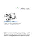
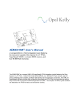
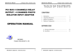
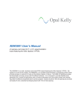
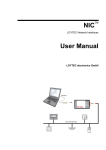
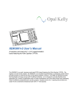
Opal Kelly
XEM6110 User’s Manual
A compact (75mm x 50mm) integration board featuring
the Xilinx Spartan-6 FPGA, external PCI Express, and
on-board SDRAM.
The XEM6110 is a compact external PCI Express FPGA integration module featuring the Xilinx Spartan-6 FPGA, 1 Gb (64 Mx16-bit) DDR2 SDRAM, high-efficiency switching power supplies, and two highdensity 0.8-mm expansion connectors. The external PCI Express interface provides fast configuration
downloads without requiring a PC reboot and PC-FPGA communication as well as easy access with our
popular FrontPanel application and SDK. A low-jitter 100 MHz oscillator is also on-board.
Software, documentation, samples, and related materials are
Copyright © 2010-2011 Opal Kelly Incorporated.
Opal Kelly Incorporated
Portland, Oregon
http://www.opalkelly.com
All rights reserved. Unauthorized duplication, in whole or part, of this document by any means except for brief
excerpts in published reviews is prohibited without the express written permission of Opal Kelly Incorporated.
Opal Kelly, the Opal Kelly Logo, and FrontPanel are trademarks of Opal Kelly Incorporated.
Linux is a registered trademark of Linus Torvalds. Microsoft and Windows are both registered trademarks of
Microsoft Corporation. All other trademarks referenced herein are the property of their respective owners and no
trademark rights to the same are claimed.
Revision History:
Date
Description
20101201
Initial release.
20110406
Added note and reference regarding LVDS output restriction for Spartan-6.
Contents
Introducing the XEM6110. . . . . . . . . . . . . . . . . . . . . . . . 5
PCB Footprint. . . . . . . . . . . . . . . . . . . . . . . . . . . . . . . . . . . . . 5
BRK6110 Breakout Board. . . . . . . . . . . . . . . . . . . . . . . . . 5
Functional Block Diagram. . . . . . . . . . . . . . . . . . . . . . . . . . . . 6
Power Supply. . . . . . . . . . . . . . . . . . . . . . . . . . . . . . . . . . . . . 6
PCI Express 1.1 Interface. . . . . . . . . . . . . . . . . . . . . . . . . . . . 6
On-board Peripherals. . . . . . . . . . . . . . . . . . . . . . . . . . . . . . . 7
Low-Jitter Crystal Oscillator. . . . . . . . . . . . . . . . . . . . . . . 7
128-MByte Word-Wide DDR2 Synchronous DRAM. . . . 7
LEDs. . . . . . . . . . . . . . . . . . . . . . . . . . . . . . . . . . . . . . . . . 7
Expansion Connectors. . . . . . . . . . . . . . . . . . . . . . . . . . . . . . 7
FrontPanel Support. . . . . . . . . . . . . . . . . . . . . . . . . . . . . . . . . 8
Programmer’s Interface. . . . . . . . . . . . . . . . . . . . . . . . . . 8
Applying the XEM6110. . . . . . . . . . . . . . . . . . . . . . . . . . 9
Powering the XEM6110. . . . . . . . . . . . . . . . . . . . . . . . . . . . . . 9
Power Budget. . . . . . . . . . . . . . . . . . . . . . . . . . . . . . . . . . 9
Supply Heat Dissipation (IMPORTANT!!). . . . . . . . . . . . . 10
Host Interface. . . . . . . . . . . . . . . . . . . . . . . . . . . . . . . . . . . . . 10
PCI Express. . . . . . . . . . . . . . . . . . . . . . . . . . . . . . . . . . . 10
LEDs. . . . . . . . . . . . . . . . . . . . . . . . . . . . . . . . . . . . . . . . . . . . 11
Low-Jitter 100-MHz Crystal Oscillator. . . . . . . . . . . . . . . . . . 11
DDR2 SDRAM. . . . . . . . . . . . . . . . . . . . . . . . . . . . . . . . . . . . 12
Clock Configuration (Source Synchronous). . . . . . . . . . . 12
Memory Controller Blocks . . . . . . . . . . . . . . . . . . . . . . . . 12
MIG Settings. . . . . . . . . . . . . . . . . . . . . . . . . . . . . . . . . . . 13
JTAG. . . . . . . . . . . . . . . . . . . . . . . . . . . . . . . . . . . . . . . . . . . . 13
Expansion Connectors. . . . . . . . . . . . . . . . . . . . . . . . . . . . . . 13
JP1. . . . . . . . . . . . . . . . . . . . . . . . . . . . . . . . . . . . . . . . . . 13
JP2. . . . . . . . . . . . . . . . . . . . . . . . . . . . . . . . . . . . . . . . . . 13
Setting I/O Voltages. . . . . . . . . . . . . . . . . . . . . . . . . . . . . 14
Considerations for Differential Signals. . . . . . . . . . . . . . . 14
BRK6110 Breakout Board. . . . . . . . . . . . . . . . . . . . . . . . . . . . 15
PCI Express Cable Selection. . . . . . . . . . . . . . . . . . . . . . . . . 15
Differences Between the XEM3010 and XEM6110 . . . . . . . . 17
USB 2.0 → PCI Express . . . . . . . . . . . . . . . . . . . . . . . . . 17
Cypress PLL → FPGA-based PLLs. . . . . . . . . . . . . . . . . 17
I2C Connections → FPGA-based I2C Controller . . . . . . . 17
Four I/O Banks → Two I/O Banks. . . . . . . . . . . . . . . . . . . 17
DC Power Connector → Expansion Connectors. . . . . . . 17
32 MiB SDR SDRAM → 128 MiB DDR2 SDRAM. . . . . . 17
XEM6110 Mechanical Drawing . . . . . . . . . . . . . . . . . . . 18
BRK6110 Mechanical Drawing. . . . . . . . . . . . . . . . . . . . 19
XEM6110 Quick Reference. . . . . . . . . . . . . . . . . . . . . . 20
XEM6110 Quick Reference. . . . . . . . . . . . . . . . . . . . . . 21
XEM6110 User’s Manual
4
www.opalkelly.com
XEM6110 User’s Manual
Introducing the XEM6110
The XEM6110 is a compact FPGA board featuring the Xilinx Spartan-6 FPGA. It is an external
1-lane PCI Express device capable of live reconfiguration (without powering down the connected host) and high-speed communication. Designed as a full-featured integration system,
the XEM6110 provides access to over 110 I/O pins on its 484-pin Spartan-6 device and has
a 128-MiByte DDR2 SDRAM available to the FPGA. The XEM6110 is designed to work with
medium-sized FPGA designs with a wide variety of external interface requirements.
PCB Footprint
A mechanical drawing of the XEM6110 is shown at the end of this manual. The PCB is 75mm
x 50mm with four mounting holes (M2 metric screws) spaced as shown in the figure. These
mounting holes are electrically isolated from all signals on the XEM6110. The PCI Express connector (Molex 74960-3018) is mounted flush to the PCB edge.
The XEM6110 has two high-density 80-pin connectors on the bottom side which provide access
to many FPGA pins, power, and JTAG.
BRK6110 Breakout Board
A simple breakout board (the BRK6110) is provided as an optional accessory to the XEM6110.
This breakout board provides DC power and easy access to the high-density connectors on the
XEM6110 by routing them to lower-density 2mm-spaced thru-holes. The breakout board also
provides a convenient reference for building boards that will mate to the XEM6110.
Opal Kelly reserves the right to change the form-factor and possibly pinout of the BRK6110.
Therefore, unlike the XEM6110, it is not intended or recommended for production integration.
www.opalkelly.com
5
XEM6110 User’s Manual
Full schematics and Gerber artwork files for the BRK6110 are provided free of charge. If your
application depends on the existing form-factor, you may reproduce this board from these documents.
A mechanical drawing of the BRK6110 is also shown at the end of this document.
Functional Block Diagram
DDR2 SDRAM
128 MiB
PCIe
PCI Express
Interface
Host Interface
Bus
Low-Jitter
100 MHz
Spartan-6 FPGA
(XC6SLX45-2FGG484)
LVDS
61 I/O
63 I/O
8 LEDs
Samtec Expansion Connector
Samtec Expansion Connector
Power Supply
The XEM6110 is designed to be operated from a 5-volt power source supplied through the expansion connectors on the bottom of the device. This provides power for the three high-efficiency switching regulators on-board to provide 3.3v, 1.8v and 1.2v. 0.9v is derived from the 3.3-volt
supply using a small low-dropout (LDO) regulator for use as a DDR2 termination voltage. Each
of the three switching regulators can provide up to 2A of current.
PCI Express 1.1 Interface
The XEM6110 is an external, 1-lane PCI Express device which connects to a supporting host
computer using a standard PCI Express cable. A repeater/equalizer inside the host computer
converts the backplane PCI Express into the cabled standard. The Opal Kelly PCI1001 host
interface board is used for this conversion.
As a PCI Express peripheral, the XEM6110 is supported by the Opal Kelly PCI Express driver.
The Opal Kelly FrontPanel Application and FrontPanel API can be used to download configuration bitfiles to the FPGA after the host computer has booted. After FPGA configuration, highspeed communication between the host and XEM6110 is enabled. The FPGA may be reconfigured any number of times without rebooting the host computer.
6
www.opalkelly.com
XEM6110 User’s Manual
XEM6110
FPGA Integration Module
PCI1001
Host Interface Board
On-board Peripherals
The XEM6110 is designed to compactly support a large number of applications with a small number of on-board peripherals. These peripherals are listed below.
Low-Jitter Crystal Oscillator
A fixed-frequency, 100 MHz, low-jitter crystal oscillator is include on-board and outputs LVDS to
the FPGA. The Spartan-6 FPGA can produce a wide range of clock frequencies using the onchip DCM and PLL capabilities.
128-MByte Word-Wide DDR2 Synchronous DRAM
The XEM also includes a 128-MByte DDR2 SDRAM with a full 16-bit word-wide interface to the
FPGA. This SDRAM is attached exclusively to the FPGA and does not share any pins with the
expansion connector. The maximum clock rate of the SDRAM is 266 MHz.
The DDR2 SDRAM is a Micron MT47H64M16HR-3:G (or compatible).
LEDs
Eight LEDs and are available for general use as debug outputs.
Expansion Connectors
Two high-density, 80-pin expansion connectors are available on the bottom-side of the XEM6110
PCB. These expansion connectors provide user access to several power rails on the XEM6110,
the JTAG interface on the FPGA, and 124 non-shared I/O pins on the FPGA, including several
GCLK inputs.
The connectors on the XEM6110 are Samtec part number: BSE-040-01-F-D-A. The table below
lists the appropriate Samtec mating connectors along with the total mated height.
Samtec Part Number
Mated Height
BTE-040-01-F-D-A
5.00mm (0.197”)
www.opalkelly.com
7
XEM6110 User’s Manual
Samtec Part Number
Mated Height
BTE-040-02-F-D-A
8.00mm (0.315”)
BTE-040-03-F-D-A
11.00mm (0.433”)
BTE-040-04-F-D-A
16.10mm (0.634”)
BTE-040-05-F-D-A
19.10mm (0.752”)
FrontPanel Support
The XEM6110 is fully supported by Opal Kelly’s FrontPanel software. FrontPanel augments the
limited peripheral support with a host of PC-based virtual instruments such as LEDs, hex displays, pushbuttons, toggle buttons, and so on. Essentially, this makes your PC a reconfigurable
I/O board and adds tremendous value to the XEM6110 as an experimentation or prototyping
system.
Programmer’s Interface
In addition to complete support within FrontPanel, the XEM6110 is also fully supported by the
FrontPanel programmer’s interface (API), a powerful C++ class library available to Windows programmers allowing you to easily interface your own software to the XEM.
In addition to the C++ library, wrappers have been written for C#, Java, and Python making the
API available under those languages as well. Sample wrappers are also provided for Matlab and
LabVIEW.
Complete documentation and several sample programs are installed with FrontPanel.
8
www.opalkelly.com
XEM6110 User’s Manual
Applying the XEM6110
Powering the XEM6110
The XEM6110 requires that this supply be clean, filtered, and within the range of 4.5v to 5.5v.
This supply must be delivered through the +VDC pins on the two device’s two expansion connectors.
The expansion bus has several power supply pins, described below:
•
•
•
•
•
+VDC is provided by an external device to the XEM6110. It must be a clean, filtered supply within the range of +4.5 volts and +5.5 volts.
+3.3v is the output of a 2-Amp switching regulator on the XEM6110.
+1.8v is the output of a 2-Amp switching regulator on the XEM6110.
+1.2v is the output of a 2-Amp switching regulator on the XEM6110.
+VCCO0 is the bank-0 I/O voltage to the FPGA. Factory default is +3.3v
•
+VCCO1 is the bank-1 I/O voltage to the FPGA. Factory default is +3.3v
Power Budget
The table below can help you determine your power budget for each supply rail on the XEM6110.
All values are highly dependent on the application, speed, usage, and so on. Entries we have
made are based on typical values presented in component datasheets or approximations based
on Xilinx power estimator results. Shaded boxes represent unconnected rails to a particular
component. Empty boxes represent data that the user must provide based on power estimates.
The user may also need to adjust parameters we have already estimated (such as FPGA Vcco
values) where appropriate.
www.opalkelly.com
9
XEM6110 User’s Manual
Component(s)
1.2v
1.8v
3.3v
PCI Express
170 mW
550 mW
130 mW
600 mW
250 mW
DDR2
FPGA Vccint
FPGA Vccaux
250 mW
FPGA Vcco3 (DDR2), est.
250 mW
FPGA Vcco2 (PCIe), est.
500 mW
FPGA Vcco0,1
Total:
Available: 2,400 mW
3,600 mW
6,600 mW
Supply Heat Dissipation (IMPORTANT!!)
Due to the limited area available on the small form-factor of the XEM6110 and the density of logic
provided, heat dissipation may be a concern. This depends entirely on the end application and
cannot be predicted in advance by Opal Kelly. Heat sinks may be required on any of the devices
on the XEM6110. Of primary focus should be the FPGA (U10), the two PCIe interface devices
(U1, U2), and the SDRAM (U11). Although the switching supplies are high-efficiency, they are
very compact and consume a small amount of PCB area for the current they can provide.
If you plan to put the XEM6110 in an enclosure, be sure to consider heat dissipation in your design.
Host Interface
There are 57 signals (29 inputs and 28 outputs) that connect the on-board PCI Express bridge
to the FPGA. These signals comprise the host interface on the FPGA and connect to the host
interface IP provided by Opal Kelly that you incorporate into your HDL design.
A number of synthesis and mapping constraints must be used to properly map the signals to
pin locations, I/O standards, and other timing requirements. Each of the samples installed with
FrontPanel includes a copy of a template constraints file that lists all the XEM6110 pins and maps
them to the appropriate FPGA pins using LOC (location) constraints. You can use this template
to quickly get the pin locations correct on a new design.
PCI Express
The XEM6110 is a PCI Express peripheral which connects to the PC using the external PCI
Express cabling to a host interface board (HIB) which resides inside the PC. The HIB plugs into
one of the standard 1-lane PCI Express slots of a typical desktop motherboard.
Although the XEM6110 is an external device, it should generally be treated as an internal device
in some respects. Notably, external PCI Express devices must be powered up before booting the
PC and must remain powered until turning off the PC. Unlike standards such as USB or Firewire,
the hot-plugging is not supported by most operating systems.
The PCI Express implementation in the XEM6110 is a two-part implementation. The first part
is dedicated silicon on the XEM6110 that is able to configure the FPGA at any time. This silicon
enumerates the XEM6110 as a PCI Express device even without any FPGA configuration. The
second part is IP provided by Opal Kelly that is built along with your FPGA application. This
10
www.opalkelly.com
XEM6110 User’s Manual
component resides inside the FPGA and serves as the host interface between the dedicated PCI
Express silicon and your FPGA application.
Because part of the PCI Express implementation resides within the FPGA with your design, it is
possible that, during development, certain situations can occur that would crash the PC hardware. For this reason, we highly recommend that development be done using a dedicated PC
that is not mission-critical and can tolerate the unexpected hardware crash.
For pin mappings to the PCI Express host interface, please see our sample UCF files. You can
use these UCF files as a basis for your design.
LEDs
There are eight LEDs on the XEM6110. Each is wired directly to the FPGA according to the pin
mapping tables at the end of this document.
The LED anodes are connected to a pull-up resistor to +3.3VDD and the cathodes wired directly
to the FPGA on Bank 3 with a bank I/O voltage of 1.8v. To turn ON an LED, the FPGA pin should
be brought low. To turn OFF an LED, the FPGA pin should be at high impedance.
NOTE: Because the bank voltage is 1.8v and the LEDs are connected to 3.3v, it is important
to tri-state (set to high-impedance) the FPGA outputs in order to turn off an LED. Sending the
FPGA output to logic-1 may damage the FPGA.
The example Verilog code provides proper signals to the LED outputs.
function [7:0] xem6110_led;
input [7:0] a;
integer i;
begin
for (i=0; i<8; i=i+1) begin : u
xem6110_led[i] = (a[i]==1’b1) ? (1’b0) : (1’bz);
end
end
endfunction
assign led = xem6110_led(count);
// Output counter value to LEDs.
Low-Jitter 100-MHz Crystal Oscillator
A 100-MHz crystal oscillator with LVDS output is attached directly to the FPGA on pins Y11 and
AB11 (Bank 2). The oscillator is a Crystek CCLD-033-50-100.000 or equivalent and features
50ppm frequency stability and phase jitter of 0.5ps typical (1ps RMS max) over 12 kHz to 80
MHz.
The differential input can be converted to a single-ended clock signal by instantiating an IBUFGDS component as shown in the Verilog below.
IBUFGDS # (
.IOSTANDARD(“LVDS_25”)
) osc_clk (
.O(clk), .I(sys_clkp), .IB(sys_clkn)
);
www.opalkelly.com
11
XEM6110 User’s Manual
DDR2 SDRAM
The Micron DDR2 SDRAM is connected exclusively to the 1.8-v I/O on Bank 3 of the FPGA. The
tables below list these connections.
DDR2 Pin
FPGA Pin
DDR2 Pin
FPGA Pin
CK
H4
A9
E1
CK
H3
A10
G4
CKE
D2
A11
C1
CS
C3
A12
D1
RAS
K5
BA0
G3
CAS
K4
BA1
G1
WE
F2
BA2
F1
LDQS
L3
D0
N3
LDQS
L1
D1
N1
UDQS
T2
D2
M2
UDQS
T1
D3
M1
LDM
L4
D4
J3
UDM
M3
D5
J1
ODT
J6
D6
K2
A0
H2
D7
K1
A1
H1
D8
P2
A2
H5
D9
P1
A3
K6
D10
R3
A4
F3
D11
R1
A5
K3
D12
U3
A6
J4
D13
U1
A7
H6
D14
V2
A8
E3
D15
V1
Clock Configuration (Source Synchronous)
The DDR2 clocking is designed to be source-synchronous from the FPGA. This means that the
FPGA sends the clock signal directly to the SDRAM along with control and data signals, allowing
very good synchronization between clock and data.
Memory Controller Blocks
Spartan-6 has integrated memory control blocks to communicate with the external DDR2 memory on the XEM6110. This is instantiated using the Xilinx Core Generator (memory interface
generator, or MIG) to create a suitable memory controller for your design. You should read and
become familiar with the DDR2 SDRAM datasheet as well as MIG and the core datasheet. Although MIG can save a tremendous amount of development time, understanding all this information is critical to building a working DDR2 memory interface.
The XEM6110 provides 1.2v as Vccint. According to the memory controller block documentation,
the Spartan-6, -2 speed grade can operate memory to 312.5 MHz with this internal voltage.
12
www.opalkelly.com
XEM6110 User’s Manual
MIG Settings
The following are the settings used to generate the MIG core for our RAMTester sample using
Xilinx Core Generator. These settings were used with ISE 12.2 and MIG 2.3. Note that settings
may be slightly different for different versions of ISE or MIG.
Frequency
Memory Type
Memory Part
Data Width
Enable DQS Enable
High-temp self-refresh
Output drive strength
RTT(nominal)
DCI for DQ/DQS
DCI for address/control
ZIO pin
RZQ pin
Calibrated Input Selection
Class for address/control
Debug signals
System clock
312.5 MHz
Component
MT47H64M16XX-3 (1Gb, x16)
16
CHECKED
DISABLED
Reducedstrength
50 ohms
CHECKED
CHECKED
Y2
K7
Yes
Class II
Your option
Differential
[default]
JTAG
The JTAG connections on the FPGA are wired directly to the expansion connector JP1 on the
XEM6110 to facilitate FPGA configuration and ChipScope usage using a Xilinx JTAG cable. The
BRK6110 has these signals connected to a 2-mm header compatible with the Xilinx JTAG cable.
Expansion Connectors
JP1
JP1 is an 80-pin high-density connector providing access to FPGA Bank 1. Several pins (38, 40,
54, 58, 59, 61, 77, and 79) of this connector are wired to global clock inputs on the FPGA and can
therefore be used as inputs to the global clock network.
Pin JP1-10 is connected to the Vref pins of Bank 1.
Pin mappings for JP1 are listed at the end of this document in the “Quick Reference” section. For
each JP1 pin, the corresponding board connection is listed. For pins connected to the FPGA, the
corresponding FPGA pin number is also shown. Finally, for pins routed to differential pair I/Os
on the FPGA, the FPGA signal names and routed track lengths have been provided to help you
equalize lengths on differential pairs.
JP2
JP2 is an 80-pin high-density connector providing access to FPGA Banks 0 and 1. Several pins
(42, 44, 59, 61, 64, 66, 77, and 79) of this connector are wired to global clock inputs on the FPGA
and can therefore be used as inputs to the global clock network.
Pin mappings for JP2 are listed at the end of this document in the “Quick Reference” section. For
each JP2 pin, the corresponding board connection is listed. For pins connected to the FPGA,
the corresponding FPGA pin number is also shown. Finally, for pins routed to differential pair I/
www.opalkelly.com
13
XEM6110 User’s Manual
Os on the FPGA, the FPGA signal names and routed track lengths have been provided to help
you equalize lengths on differential pairs.
Setting I/O Voltages
The Spartan-6 FPGA allows users to set I/O bank voltages in order to support several different
I/O signalling standards. This functionality is supported by the XEM6110 by allowing the user to
connect independent supplies to the FPGA VCCO pins on two of the FPGA banks.
By default, ferrite beads have been installed which attach each VCCO bank to the +3.3VDD
supply. If you intend to supply power to a particular I/O bank, you MUST remove the appropriate
ferrite beads. Power can then be supplied through the expansion connectors.
The table below lists details for user-supplied I/O bank voltages
I/O Bank
Expansion Pins
Ferrite Bead
0
JP2-36, 56
FB2
1
JP1-35, 55
FB1
Considerations for Differential Signals
The XEM6110 PCB layout and routing has been designed with several applications in mind,
including applications requiring the use of differential (LVDS) pairs. Please refer to the Xilinx
Spartan-6 datasheet for details on using differential I/O standards with the Spartan-6 FPGA.
Note: LVDS output on the Spartan-6 is restricted to banks 0 and 2. LVDS input is available on
all banks. For more information, please refer to the Spartan-6 FPGA SelectIO Resources User
Guide from Xilinx.
FPGA I/O Bank Voltages
In order to use differential I/O standards with the Spartan-6, you must set the VCCO voltages for
the appropriate banks to 2.5v according to the Xilinx Spartan-6 datasheet. Please see the section above entitled “Setting I/O Voltages” for details.
Characteristic Impedance
The characteristic impedance of all routes from the FPGA to the expansion connector is approximately 50-Ω.
Differential Pair Lengths
In many cases, it is desirable that the route lengths of a differential pair be matched within some
specification. Care has been taken to route differential pairs on the FPGA to adjacent pins on the
expansion connectors whenever possible. We have also included the lengths of the board routes
for these connections to help you equalize lengths in your final application. Due to space constraints, some pairs are better matched than others.
Reference Voltage Pins (Vref)
The Xilinx Spartan-6 supports externally-applied input voltage thresholds for some input signal
standards. The XEM6110 supports these Vref applications for banks 0 and 1:
14
www.opalkelly.com
XEM6110 User’s Manual
For Bank 0, the four Vref pins are routed to expansion connector JP1 on pins 48, 51, 62, and 65.
Note that all four must be connected to the same voltage for proper application of input thresholds. Please see the Xilinx Spartan-6 documentation for more details.
For Bank 1, the four Vref pins are connected to a single pin on expansion connector JP1, pin 10.
BRK6110 Breakout Board
The BRK6110 is a simple two-layer “breakout board” which can be used to evaluate or transition
to the XEM6110. It provides standard 2-mm thru-hole connections to the 0.8-mm high-density
connectors on the XEM6110 and a DC power connector (2.1mm/5.5mm, center positive) for providing +VDC to the XEM6110.
The corresponding connections to the XEM6110 are labelled in silkscreen on the BRK6110. The
BRK6110 connectors essentially mirror the connections on the XEM6110. For example, the JP1
connector on the XEM6110 mates to JP1 on the BRK6110 and is electrically connected to JP1A
and JP1B on the BRK6110 according to the table below.
Note that the pins on JP1 (the Samtec connector) are routed to two headers denoted as JP1A
and JP1B. JP1A pins are numbered 1-40. JP1B pins are numbered 41-80. This is to map them
to the single Samtec connector.
BRK6110
XEM6110
JP1A-1
JP1-1
JP1A-2
JP1-2
JP1A-3
JP1-3
JP1A-4
JP1-4
...
...
JP1B-78
JP1-78
JP1B-79
JP1-79
JP1B-80
JP1-80
A similar relationship holds for JP2, JP2A, and JP2B.
PCI Express Cable Selection
The XEM6110 is designed as an external PCI Express device. The Opal Kelly PCI1001 is a x1
PCI Express host interface board (HIB) which is inserted into the PC in a x1 PCI Express slot.
Both the XEM6110 and PCI1001 contain devices which equalize and retime the high-speed serial signals to improve signal integrity. These devices can require different equalization settings
depending on the cable length between the PCI100 and XEM6110.
On the XEM6110, these settings are determined by jumpers on the header JP3. On the
PCI1001, these settings are determined by jumpers on the header JP1. The jumper setting
should be the same on both devices.
For a given cable length, insert a jumper between the pins as indicated in the table below. Insert
the jumper where a solid circle is indicated. Remove the jumper where a hollow circle is indicated. By default, all boards are shipped with all jumpers installed (3-meter cable selected).
www.opalkelly.com
15
XEM6110 User’s Manual
16
Cable Length
Molex P/N
1-2 3-4 5-6
1 meter
74576-0001
○
○
○
3 meters
74576-0003
●
●
●
5 meters
74576-0005
○
●
○
7 meters
74576-0007
○
●
●
www.opalkelly.com
XEM6110 User’s Manual
Differences Between the XEM3010 and XEM6110
The XEM6110 was designed to be as compatible as possible with our XEM3010 in order to
facilitate customer design migration with minimal changes. The differences between these two
products are highlighted below.
USB 2.0 → PCI Express
The most dramatic upgrade is the 1-lane PCI Express interface which replaces the USB 2.0
interface. PCI Express is significantly faster and still allows FPGA reconfiguration over the interface without shutting down the computer. However, plug-and-play is not currently supported by
most operating systems for PCI Express, so the device must be turned on before the PC boots.
Cypress PLL → FPGA-based PLLs
There is no on-board PLL on the XEM6110. Spartan-6 adds on-chip PLLs with similar functionality and the trade-off is a lower-jitter clock oscillator on the XEM6110.
I2C Connections → FPGA-based I2C Controller
The XEM6110 does not have the I2C connections on its expansion connectors. These have been
replaced with new routes to the FPGA so that existing designs may incorporate a user-supplied
I2C controller into the FPGA fabric.
Four I/O Banks → Two I/O Banks
The Spartan-3 device used on the XEM3010 has 6 I/O banks, four of which are routed to the expansion connectors. Each of these four has selectable I/O bank voltages. The Spartan-6 device
on the XEM6110 only has four total I/O banks, two of which are routed to the expansion connectors. This is a consideration in designs where multiple I/O bank voltages were used.
Note: LVDS output on the Spartan-6 is restricted to banks 0 and 2. LVDS input is available on
all banks. For more information, please refer to the Spartan-6 FPGA SelectIO Resources User
Guide from Xilinx.
DC Power Connector → Expansion Connectors
Due to space constraints, the XEM6110 no longer has a DC power connector. 5-v DC power
must be delivered to the device through the expansion connectors. The BRK6110 provides such
power with the same connector found on the XEM3010.
32 MiB SDR SDRAM → 128 MiB DDR2 SDRAM
The XEM3010 has 32 MiB of on-board single-data-rate SDRAM. The XEM6110 replaces this
with a faster, higher-capacity 128-MiB double-data-rate SDRAM. The Spartan-6 also has an
internal memory control block (MCB) which provides a DDR2 controller to designs without consuming significant FPGA fabric.
www.opalkelly.com
17
XEM6110 User’s Manual
XEM6110 Mechanical Drawing
50
2.
50.00
47.00
50.00
47.00
41.63
35.74
19.86
6.86
3.00
0
0.24
72.00
75.00
57.48
20.07
0
3.00
3.00
0.00
25.50
50.00
15.88
45.00
5.00
0
50.00
30.11
34.26
0
9.25
8.15
5.61
3.07
1.57
0.00
10.13
14.29
6.59
All dimensions in mm
18
www.opalkelly.com
XEM6110 User’s Manual
BRK6110 Mechanical Drawing
All dimensions in mm.
120.00
117.00
112.71
111.00
108.56
106.41
98.00
92.73
73.00
65.00
58.26
29.00
27.00
www.opalkelly.com
77.00
78.00
80.00
62.00
47.64
57.97
18.08
31.29
33.61
17.96
18.00
0
3.00
4.00
8.82
3.00
0
19
XEM6110 User’s Manual
XEM6110 Quick Reference
JP1
Pin
Connection
JP1
Pin
Connection
1
DGND
2
+3.3VDD
3
-
4
+3.3VDD
5
JTAG_TCK
6
+3.3VDD
7
JTAG_TMS
8
JTAG_TDO
9
JTAG_TDI
10
VREF_1
11
C19
12
-
13
DGND
14
DGND
15
G16
L9P_1
37.939
16
G19
L33P_1
60.218
17
G17
L9N_1
37.791
18
F20
L33N_1
56.677
19
H19
L34P_1
39.405
20
H20
L38P_1
52.874
21
H18
L34N_1
36.649
22
J19
L38N_1
52.611
23
F16
L10P_1
36.908
24
D19
L29P_1
47.273
25
F17
L10N_1
37.537
26
D20
L29N_1
46.537
27
J17
L36P_1
34.410
28
F18
L30P_1
39.799
29
K17
L36N_1
32.463
30
F19
L30N_1
40.267
31
K16
L21P_1
28.716
32
M16
L58P_1
27.342
33
J16
L21N_1
29.917
34
L15
L58N_1
29.284
35
+VCCO1
36
DGND
37
V21
L52P_1
16.858
38
K20
L40P_GCLK11_1
29.040
39
V22
L52N_1
17.151
40
K19
L40N_GCLK10_1
28.878
41
T21
L50P_1
23.203
42
U20
L51P_1
23.720
43
T22
L50N_1
22.284
44
U22
L51N_1
22.417
45
P21
L48P_1
23.132
46
R20
L49P_1
26.371
47
P22
L48N_1
22.276
48
R22
L59N_1
24.648
49
M21
L46P_1
25.990
50
N20
L47P_1
26.822
51
M22
L46N_1
24.527
52
N22
L47N_1
25.168
53
L20
L45P_1
22.274
54
M20
L42P_GCLK7_1
21.180
55
+VCCO1
56
DGND
57
L22
L45N_1
20.797
58
L19
L42N_GCLK6_1
24.190
59
H21
L41P_GCLK9_1
25.953
60
K21
L44P_1
24.187
61
H22
L41N_GCLK8_1
25.014
62
K22
L44N_1
23.603
63
F21
L37P_1
28.198
64
G20
L39P_1
27.676
65
F22
L37N_1
26.589
66
G22
L39N_1
26.067
67
D21
L31P_1
32.225
68
E20
L35P_1
31.492
69
D22
L31N_1
31.347
70
E22
L35N_1
30.055
71
B21
L19P_1
31.387
72
C20
L32P_1
33.935
73
B22
L19N_1
30.050
74
C22
L32N_1
32.266
75
A21
L20N_1
33.836
76
A20
L20P_1
34.325
77
J20
L43P_GCLK5_1
24.102
78
DGND
79
J22
L43N_GCLK4_1
24.092
80
DGND
20
FPGA Pin
L1P_1
Length
(mm)
48.657
Length
(mm)
FPGA Pin
Bank 1 VREF
www.opalkelly.com
LED
FPGA Pin
D2
H8
D3
B2
D4
B1
D5
G7
D6
F7
D7
D3
D8
C4
D9
E5
Clock Signal Connection
FPGA Pin
OSC_P
IO_L32P_GCLK29_2
Y11
OSC_N
IO_L32N_GCLK28_2
AB11
XEM6110 User’s Manual
XEM6110 Quick Reference
JP2
Pin
Connection
JP2
Pin
Connection
FPGA Pin
Length
(mm)
1
3
+VDC
2
DGND
+VDC
4
+1.2VDD
5
+VDC
6
+1.2VDD
7
+1.8VDD
8
9
+3.3VDD
10
H16
L28P_1
41.328
P19
L59P_1
11
+3.3VDD
47.476
12
P20
L59N_1
13
+3.3VDD
51.807
14
DGND
15
W20
L60P_1
17
W22
L60N_1
51.907
16
T19
L74P_1
38.591
53.606
18
T20
L74N_1
19
U19
40.628
L70P_1
49.057
20
P17
L72P_1
21
39.602
V20
L70N_1
50.597
22
N16
L72N_1
33.852
23
C5
L2P_0
27.507
24
M17
L71P_1
34.813
25
A5
L2N_0
27.626
26
M18
L71N_1
34.914
27
D14
L49P_0
41.204
28
P18
L73P_1
36.711
29
C14
L49N_0
37.149
30
R19
L73N_1
39.280
31
E16
L66P_0
36.786
32
D9
L7P_0
30.242
33
D17
L66N_0
37.192
34
C8
L7N_0
26.971
35
DGND
36
+VCCO0
37
D7
L32P_0
23.590
38
D10
L33P_0
26.222
39
D8
L32N_0
24.146
40
C10
L33N_0
25.323
41
L17
L61P_1
44.830
42
D11
L36P_GCLK15_0
26.539
43
K18
L61N_1
44.133
44
C12
L36N_GCLK14_0
26.506
45
D6
L3P_0
18.185
46
D15
L62P_0
33.337
47
C6
L3N_0
17.482
48
C16
L62N_VREF_0
32.259
49
A3
L1P_HSWAPEN_0
13.928
50
B6
L4P_0
12.838
51
A4
L1N_VREF_0
13.018
52
A6
L4N_0
12.356
53
B8
L6P_0
18.615
54
C7
L5P_0
17.275
55
DGND
56
+VCCO0
57
A8
L6N_0
17.038
58
A7
L5N_0
12.741
59
B10
L34P_GCLK19_0
20.080
60
C9
L8P_0
17.926
61
A10
L34N_GCLK18_0
18.748
62
A9
L8N_VREF_0
14.028
63
C13
L38P_0
25.099
64
B12
L37P_GCLK13_0
20.996
65
A13
L38N_VREF_0
22.706
66
A12
L37N_GCLK12_0
20.055
67
C15
L51P_0
25.362
68
B14
L50P_0
21.102
69
A15
L51N_0
23.293
70
A14
L50N_0
19.964
71
C17
L64P_0
27.660
72
B16
L63P_0
24.506
73
A17
L64N_0
25.374
74
A16
L63N_0
22.571
75
A18
L65N_0
25.971
76
B18
L65P_0
26.046
77
C11
L35P_GCLK17_0
18.067
78
DGND
79
A11
L35N_GCLK16_0
18.060
80
DGND
FPGA Pin
Length
(mm)
www.opalkelly.com
21