1
Gearmotors \ Industrial Gear Units \ Drive Electronics \ Drive Automation \ Services
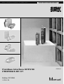
Fieldbus Interface DFP21B
PROFIBUS DP-V1
Edition 07/2006
11479019 / EN
FA375100
Manual
SEW-EURODRIVE – Driving the world
1 Important Notes...................................................................................................... 6
1.1 Explanation of symbols .................................................................................. 6
1.2 Part of the product ......................................................................................... 6
1.3 Documentation reference............................................................................... 6
1.4 Liability for defects ......................................................................................... 7
1.5 Product names and trademarks ..................................................................... 7
1.6 Disposal ......................................................................................................... 7
2 Safety Notes ........................................................................................................... 8
2.1 Preliminary information .................................................................................. 8
2.2 General safety notes ...................................................................................... 8
2.2.1 General safety notes for bus systems.................................................. 8
2.3 Transport / storage......................................................................................... 8
2.4 Installation / assembly.................................................................................... 9
2.5 Startup / operation ......................................................................................... 9
3 Introduction .......................................................................................................... 10
3.1 Content of the manual.................................................................................. 10
3.2 Additional documentation............................................................................. 10
3.3 Features ....................................................................................................... 10
3.3.1 MOVIDRIVE®, MOVITRAC® B and PROFIBUS................................ 10
3.3.2 Access to all information .................................................................... 11
3.3.3 Cyclical and acyclical data exchange via PROFIBUS DP ................. 11
3.3.4 Acyclical data exchange via PROFIBUSDP-V1................................. 11
3.3.5 Configuring the PROFIBUS option card ............................................ 12
3.3.6 Monitoring functions........................................................................... 12
3.3.7 Diagnostics ........................................................................................ 13
3.3.8 Fieldbus monitor ................................................................................ 13
4 Assembly and Installation Notes ........................................................................ 14
4.1 Installing the DFP21B option card in MOVIDRIVE® MDX61B ..................... 14
4.1.1 Before you start ................................................................................. 14
4.1.2 Installing and removing an option card .............................................. 15
4.2 Installing the DFP21B option card in MOVITRAC® B .................................. 16
4.2.1 SBus connection ................................................................................ 16
4.2.2 System bus connection...................................................................... 17
4.3 Assembling and installing the UOH11B gateway housing ........................... 18
4.4 Connection and terminal description of the DFP21B option ........................ 20
4.5 Pin assignment ............................................................................................ 21
4.5.1 MOVIDRIVE® / MOVITRAC® B / PROFIBUS connection ................. 21
4.5.2 Baud rates greater than 1.5 MBaud................................................... 21
4.6 Shielding and routing bus cables ................................................................. 22
4.7 Bus termination ............................................................................................ 22
4.8 Setting the station address .......................................................................... 23
4.9 Operating mode displays: option DFP21B ................................................... 24
4.9.1 PROFIBUS LEDs............................................................................... 24
Manual – Fieldbus Interface DFP21B PROFIBUS DP-V1
3
5 Project Planning and Startup .............................................................................. 26
5.1 Validity of the GSD files for DFP21B............................................................ 26
5.2 DP master project planning the with MOVIDRIVE® GSD file....................... 26
5.2.1 GSD file for PROFIBUSDP ................................................................ 26
5.2.2 GSD file for PROFIBUSDP-V1 .......................................................... 27
5.2.3 Project planning procedure ................................................................ 28
5.2.4 DP configuration for MOVIDRIVE® MDX61B (SEWA6003.GSD)...... 29
5.2.5 MOVIDRIVE® MDX61B external diagnostics .................................... 32
5.3 DP master project planning with MOVITRAC® or gateway GSD file ........... 34
5.3.1 GSD files for operation in MOVITRAC® B and UOH11B gateway
housing .............................................................................................. 34
5.3.2 PROFIBUS DP master startup........................................................... 35
5.3.3 Configuration of the PROFIBUSDP interface .................................... 36
5.3.4 Autosetup for gateway operation ....................................................... 40
5.4 Setting the MOVIDRIVE® MDX61B drive inverter ....................................... 42
5.5 Setting the MOVITRAC® frequency inverter ................................................ 43
6 PROFIBUS DP Operating Characteristics ......................................................... 45
6.1 Controlling the MOVIDRIVE® MDX61B drive inverter ................................. 45
6.1.1 Control example for SIMATIC S7 with MOVIDRIVE® MDX61B ........ 46
6.1.2 PROFIBUS DP timeout (MOVIDRIVE® MDX61B)............................. 46
6.1.3 Fieldbus timeout response (MOVIDRIVE® MDX61B)........................ 46
6.2 Control of the MOVITRAC® inverter (gateway)............................................ 47
6.2.1 Control example for SIMATIC S7 with MOVITRAC® B (gateway)..... 48
6.2.2 SBus timeout ..................................................................................... 48
6.2.3 Unit faults ........................................................................................... 48
6.2.4 Fieldbus timeout of the DFP21B in gateway operation...................... 49
6.3 Parameter settings via PROFIBUS DP ........................................................ 49
6.3.1 Structure of the 8-byte MOVILINK® parameter channel .................... 49
6.3.2 Reading a parameter with PROFIBUS DP (READ) ........................... 52
6.3.3 Writing a parameter via PROFIBUS DP (WRITE) ............................. 53
6.3.4 Parameter setting procedure with PROFIBUS DP............................. 54
6.3.5 Parameter data format ....................................................................... 54
6.4 SIMATIC STEP7 program example ............................................................. 55
6.5 Return codes for parameter setting.............................................................. 56
6.5.1 Elements ............................................................................................ 56
6.5.2 Error class.......................................................................................... 56
6.5.3 Error code .......................................................................................... 56
6.5.4 Additional code .................................................................................. 57
6.6 Special cases ............................................................................................... 57
6.6.1 Special return codes .......................................................................... 57
4
Manual – Fieldbus Interface DFP21B PROFIBUS DP-V1
7 PROFIBUS DP-V1 Functions ............................................................................... 59
7.1 Introduction to PROFIBUS DP-V1 ............................................................... 59
7.1.1 Class 1 master (C1 master) ............................................................... 60
7.1.2 Class 2 master (C2 master) ............................................................... 60
7.1.3 Data sets (DS) ................................................................................... 60
7.1.4 DP-V1 services .................................................................................. 61
7.1.5 DP-V1 alarm handling........................................................................ 61
7.2 Features of SEW drive inverters .................................................................. 62
7.3 Structure of the DP-V1 parameter channel .................................................. 63
7.3.1 Parameter setting procedure via data set 47 ..................................... 65
7.3.2 DP-V1 master processing sequence ................................................. 66
7.3.3 Addressing connected drive inverters................................................ 67
7.3.4 MOVILINK® parameter requests ....................................................... 67
7.3.5 PROFIdrive parameter requests ........................................................ 72
7.4 Project planning for a C1 master.................................................................. 77
7.4.1 Operating mode (DP-V1 mode) ......................................................... 77
7.4.2 Example program for SIMATIC S7 .................................................... 78
7.4.3 DP-V1 technical data for MOVIDRIVE® DFP21 ................................ 83
7.4.4 Technical data DP-V1 for the gateway operation and MOVITRAC® . 83
7.4.5 Error codes of the DP-V1 services..................................................... 84
8 Operation of MOVITOOLS® MotionStudio via PROFIBUS................................ 85
8.1 Introduction .................................................................................................. 85
8.2 Required hardware ...................................................................................... 86
8.3 Required software ........................................................................................ 86
8.4 Installation .................................................................................................... 86
8.5 Configuring SIMATIC NET ........................................................................... 87
8.6 Configuration of SEW communication server .............................................. 90
8.6.1 Establishing communication .............................................................. 90
8.6.2 Procedure .......................................................................................... 90
8.7 Automatic search for connected units (unit scan) ....................................... 93
8.8 Activating online operation ........................................................................... 93
8.9 Known problems when operating MOVITOOLS® MotionStudio .................. 94
9 Error Diagnostics ................................................................................................. 95
9.1 Diagnostic procedures ................................................................................. 95
9.2 List of errors ................................................................................................. 98
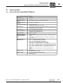
10 Technical Data ...................................................................................................... 99
10.1 Option DFP21B for MOVIDRIVE® MDX61B ................................................ 99
10.2 DFP21B option for MOVITRAC® B and UOH11B gateway housing.......... 100
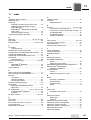
11 Index .................................................................................................................... 101
Manual – Fieldbus Interface DFP21B PROFIBUS DP-V1
5
Important Notes
Explanation of symbols
1
1
Important Notes
1.1
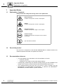
Explanation of symbols
Manual
Always follow the safety and warning notes in this publication.
Electrical hazard
Possible consequences: Severe or fatal injuries
Hazard
Possible consequences: Severe or fatal injuries
Hazardous situation
Possible consequences: Slight or minor injuries
Harmful situation
Possible consequences: Damage to the unit and the
environment
Tips and useful information
1.2
Part of the product
The manual is a component of the DFP21B PROFIBUSDP-V1 fieldbus interface and
contains important information for operation and service.
1.3
Documentation reference
•
You must adhere to the information in the documentation to ensure:
•
•
6
Fault-free operation
Fulfillment of any rights to claim under limited warranty
•
Consequently, read through this manual carefully before you start installation and
startup of the frequency inverters with the DFP21B PROFIBUS option card.
•
This manual assumes that the user has access to and is familiar with the
MOVIDRIVE® and MOVITRAC® documentation, in particular the MOVIDRIVE®
MDX60B/61B und MOVITRAC® B system manuals.
Manual – DFP21B PROFIBUSDP-V1 Fieldbus Interface
Important Notes
Liability for defects
1.4
1
Liability for defects
Incorrect handling or undertaking any action that is not specified in this manual could
impair the properties of the product. If this is the case, you lose any right to claim against
SEW-EURODRIVE GmbH & Co KG under limited warranty.
1.5
Product names and trademarks
The brands and product names named in these operating instructions are trademarks
or registered trademarks of the titleholders.
1.6
Disposal
Please follow the current national regulations.
Dispose of the following materials separately in accordance with the country-specific
regulations in force, as:
•
Electronic scrap
•
Plastics
•
Sheet metal
•
Copper
and so on
Manual – DFP21B PROFIBUSDP-V1 Fieldbus Interface
7
Safety Notes
Preliminary information
2
2
Safety Notes
•
2.1
You are only allowed to perform installation and startup of the DFP21B fieldbus interface when observing applicable accident prevention regulations and
the MOVIDRIVE® MDX60B/61B and MOVITRAC® B operating instructions.
Preliminary information
The following safety notes apply to the fieldbus interface DFP21B PROFIBUS DPV1.
Please also consider the supplementary safety notes in the individual sections of
this manual.
2.2
General safety notes
Never install or start up damaged products.
Submit a complaint to the shipping company immediately in the event of damage.
2.2.1
General safety notes for bus systems
This communication system allows you to adjust the MOVIDRIVE® drive inverter to your
specific application very accurately. As with all bus systems, there is a danger of
modifications to the parameters that are not visible from outside (in relation to the
inverter), which give rise to changes in the inverter behavior. This may result in
unexpected (not uncontrolled) system behavior.
2.3
Transport / storage
Inspect the shipment as soon as you receive the delivery and inform the shipping
company of any damage that may have occurred in transit immediately. Do not
operate the product if it is damaged.
Use suitable, sufficiently rated handling equipment if necessary.
Damage can result from incorrect storage.
Store the unit in a dry, dust-free room if it is not to be installed straight away.
8
Manual – DFP21B PROFIBUSDP-V1 Fieldbus Interface
Safety Notes
Installation / assembly
2.4
2
Installation / assembly
Adhere to the instructions in section 4, "Assembly and Installation Notes".
2.5
Startup / operation
Adhere to the instructions in section 5, "Project Planning and Startup".
Manual – DFP21B PROFIBUSDP-V1 Fieldbus Interface
9
Introduction
Content of the manual
3
3
Introduction
3.1
Content of the manual
This user manual describes how to:
3.2
•
Install the PROFIBUS DFP21B option card in the MOVIDRIVE® MDX61B drive
inverter
•
Use the PROFIBUS DFP21B option card in the MOVIDRIVE® B frequency inverter
and in the UOH11B gateway housing
•
Start up the MOVIDRIVE® B with the PROFIBUS fieldbus system
•
Start up the MOVITRAC® B with the PROFIBUS gateway
•
Configure the PROFIBUS using GSD files
•
Operate MOVITOOLS® MotionStudio via PROFIBUS
Additional documentation
For information on how to connect MOVIDRIVE® straightforwardly and effectively to the
PROFIBUS fieldbus system, in addition to this user manual about the PROFIBUS
option, you should request the following publications about fieldbus technology:
•
MOVIDRIVE® Fieldbus Unit Profile manual
•
MOVITRAC® B system manual
The manual for the MOVIDRIVE® Fieldbus Unit Profile and MOVITRAC® B system
manual describes the fieldbus parameters and their coding, and explains the whole
range of various control concepts and application options in the form of brief examples.
The MOVIDRIVE® "Fieldbus Unit Profile" manual contains a listing of all parameters of
the drive inverter which can be read and written via the various communication
interfaces, such as system bus, RS-485 and also via the fieldbus interface.
3.3
Features
The MOVIDRIVE® MDX61B drive inverter and MOVITRAC® B frequency inverter allow
you to use the DFP21B option to connect to higher-level automation systems via PROFIBUS thanks to its powerful universal fieldbus interface.
3.3.1
MOVIDRIVE®, MOVITRAC® B and PROFIBUS
The unit behavior of the inverter, which forms the basis of PROFIBUS operation, is
referred to as the unit profile. It is independent of any particular fieldbus and is therefore
a uniform feature. This feature allows the user to develop fieldbus-independent drive
applications. This makes it much easier to change to other bus systems, such as
DeviceNet (option DFD).
10
Manual – DFP21B PROFIBUSDP-V1 Fieldbus Interface
Introduction
Features
3.3.2
3
Access to all information
MOVIDRIVE® MDX61B offers digital access to all drive parameters and functions via
the PROFIBUS interface. The drive inverter is controlled via fast, cyclic process data.
Via this process data channel, you can enter setpoints such as the setpoint speed, ramp
generator time for acceleration/deceleration, etc. as well as trigger various drive
functions such as enable, control inhibit, normal stop, rapid stop, etc. However, at the
same time you can also use this channel to read back actual values from the drive
inverter, such as the actual speed, current, unit status, fault number and reference
signals.
3.3.3
Cyclical and acyclical data exchange via PROFIBUS DP
While process data exchange usually takes place cyclically, drive parameters can be
read and written acyclically via functions such as READ or WRITE or via the
MOVILINK® parameter channel. This parameter data exchange enables you to
implement applications in which all the important drive parameters are stored in the
master programmable controller, so that there is no need to make parameter settings
manually on the drive inverter itself.
3.3.4
Acyclical data exchange via PROFIBUS DP-V1
The PROFIBUS DP-V1 specification introduced new acyclical READ/WRITE services
as part of the PROFIBUSDP expansions. These acyclical services are added to the current cyclical bus operation in special telegrams to ensure compatibility of PROFIBUS DP
and PROFIBUS DP V1.
Manual – DFP21B PROFIBUSDP-V1 Fieldbus Interface
11
Introduction
Features
3
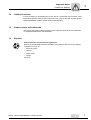
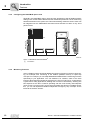
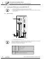
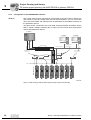
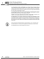
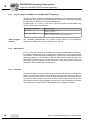
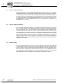
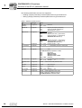
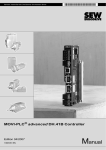
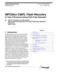
3.3.5
Configuring the PROFIBUS option card
Generally, the PROFIBUS option card has been designed so that all fieldbus-specific
settings, such as the station address and the default bus parameter can be made using
hardware switches on the option card. This manual setting means the drive inverter can
be integrated into the PROFIBUS environment and switched on within a very short
period of time.
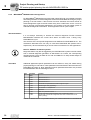
[1]
Digital I/O
Analog I/O
MOVIDRIVE® B
EURODRIVE
MOVIDRIVE® B
MOVITRAC® B
PROFIBUS Master
PROFIBUS
Figure 1: PROFIBUS with MOVIDRIVE®
[1]
3.3.6
58687AXX
Visualization
Monitoring functions
Using a fieldbus system demands additional monitoring functions in the drive engineering, for example, time monitoring of the fieldbus (fieldbus timeout) or rapid stop
concepts. For example, you can adapt MOVIDRIVE®/MOVITRAC® monitoring functions
specifically to your application. You can determine, for instance, which of the drive
inverter's fault responses should be triggered in the event of a bus error. A rapid stop is
a good idea for many applications, although this can also be achieved by "freezing" the
last setpoints so the drive continues operating with the most recently valid setpoints
(such as with a conveyor belt). As the control terminals also function in fieldbus operation, you can still implement fieldbus-independent emergency stop concepts via the
terminals of the drive inverter.
12
Manual – DFP21B PROFIBUSDP-V1 Fieldbus Interface
Introduction
Features
3.3.7
3
Diagnostics
The MOVIDRIVE® drive inverter and the MOVITRAC® B frequency inverter offer you
numerous diagnostics options for startup and service. For example, you can use the
integrated fieldbus monitor to control setpoint values sent from the higher-level control
as well as the actual values.
3.3.8
Fieldbus monitor
Furthermore, you are supplied with a variety of additional information about the status
of the fieldbus option card. The fieldbus monitor function in conjunction with the
MOVITOOLS® MotionStudio PC software offers you an easy-to-use diagnostic tool for
setting all drive parameters (including the fieldbus parameters) and for displaying the
fieldbus and device status information in detail.
Manual – DFP21B PROFIBUSDP-V1 Fieldbus Interface
13
Assembly and Installation Notes
Installing the DFP21B option card in MOVIDRIVE® MDX61B
4
4
Assembly and Installation Notes
This section contains information about assembly and installation of the DFP21B option
card in the MOVIDRIVE® MDX61B, MOVITRAC® B and UOH11B gateway housing.
4.1
Installing the DFP21B option card in MOVIDRIVE® MDX61B
Only SEW-EURODRIVE engineers are allowed to install or remove option cards
for MOVIDRIVE® MDX61B size 0.
•
4.1.1
Option cards can only be installed or removed by users for MOVIDRIVE®
MDX61B sizes 1 to 6.
Before you start
The DFP21B option card must be plugged into the fieldbus slot.
Observe the following notes before installing or removing an option card:
14
•
Disconnect the inverter from the power. Switch off the DC 24 V and the supply
voltage.
•
Take appropriate measures to protect the option card from electrostatic charge (use
discharge strap, conductive shoes, and so on) before touching it.
•
Before installing the option card, remove the keypad and the front cover.
•
After installing the option card, replace the keypad and the front cover.
•
Keep the option card in its original packaging until immediately before you are ready
to install it.
•
Hold the option card by its edges only. Do not touch any components.
Manual – DFP21B PROFIBUSDP-V1 Fieldbus Interface
Assembly and Installation Notes
Installing the DFP21B option card in MOVIDRIVE® MDX61B
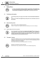
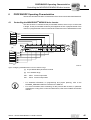
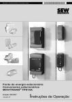
4.1.2
4
Installing and removing an option card
2.
1.
3.
4.
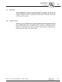
Figure 2: Installing an option card in MOVIDRIVE® MDX61B sizes 1 to 6
53001AXX
1. Remove the two retaining screws holding the card retaining bracket. Pull the card
retaining bracket out evenly from the slot (do not twist!).
2. Remove the two retaining screws of the black cover plate on the card retaining
bracket. Remove the black cover plate.
3. Position the option card onto the retaining bracket so that the three retaining screws
fit into the corresponding bores on the card retaining bracket.
4. Insert the retaining bracket with installed option card into the slot, pressing slightly so
it is seated properly. Secure the card retaining bracket with the two retaining screws.
5. To remove the option card, follow the instructions in reverse order.
Manual – DFP21B PROFIBUSDP-V1 Fieldbus Interface
15
Assembly and Installation Notes
Installing the DFP21B option card in MOVITRAC® B
4
4.2
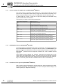
4.2.1
Installing the DFP21B option card in MOVITRAC® B
•
MOVITRAC® B does not require special firmware status.
•
Only SEW-EURODRIVE engineers are allowed to install or remove option cards for
MOVITRAC® B.
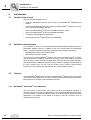
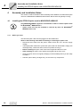
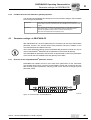
SBus connection
®
MOVITRAC B
S1
[1]
S2
DFP21B
RUN
BUS
FAULT
ON
OFF
X44
FSC11B
X45
X46
9
5
6
1
X30
HL ⊥ 1 2 3 4 5 6 7
0 1
20
21
22
23
24
25
26
AS
ADDRESS
H1
H2
X24
X12
+
24V =
–
24V IO
GND
X26
1
2
3
4
5
6
7
8
9
12 3 45 6 7
59185AXX
[1]
Terminating resistor activated, S1 = ON
The DFP21B features an integrated SBus terminating resistor and must therefore
always be installed at the beginning of the SBus connection.
The address of the DFP21B is always 0.
X46
X26
X46:1
X26:1
SC11 SBus +, CAN high
X46:2
X26:2
SC12 SBus , CAN low
X46:3
X26:3
GND, CAN GND
X46:7
X26:7
DC 24 V
X12
16
X12:8
+24-V input
X12:9
GND reference potential for the binary inputs
Manual – DFP21B PROFIBUSDP-V1 Fieldbus Interface
Assembly and Installation Notes
Installing the DFP21B option card in MOVITRAC® B
4
To simplify cabling, the DFP21B can be supplied with DC 24V from X46.7 of the
MOVITRAC® to X26.7.
MOVITRAC® must be supplied with DC 24V at terminals X12.8 and X12.9 when supplying the DFP21B by MOVITRAC®.
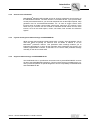
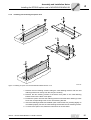
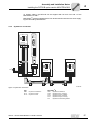
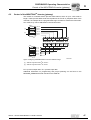
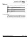
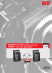
4.2.2
System bus connection
®
MOVITRAC B
S1
S2
DFP21B
RUN
BUS
FAULT
ON
OFF
X44
FSC11B
X45
9
5
6
1
X46
X30
HL^ 1 2 3 4 5 6 7
0 1
20
21
22
23
24
25
26
AS
ADDRESS
H1
H2
®
MOVITRAC B
®
MOVITRAC B
X24
S1
X12
+
24V =
-
24V IO
GND
1
2
3
4
5
6
7
8
9
S2
X26
ON
12 3 45 6 7
OFF
X44
S2
ON
OFF
X44
FSC11B
X45
S1
X46
HL ^ 1 2 3 4 5 6 7
FSC11B
X45
X46
HL ^ 1 2 3 4 5 6 7
59186AXX
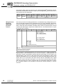
Figure 3: System bus connection
DFP
GND
SC11
SC12
= System bus reference
= System bus high
= System bus low
Manual – DFP21B PROFIBUSDP-V1 Fieldbus Interface
MOVITRAC® B
GND = System bus reference
SC22 = System bus low, outgoing
SC21 = System bus high, outgoing
SC12 = System bus low, incoming
SC11 = System bus high, incoming
S12
= System bus terminating resistor
17
4
Assembly and Installation Notes
Installing the DFP21B option card in MOVITRAC® B
Note:
•
Use a two-core twisted and shielded copper cable (data transmission cable with
braided copper shield). Connect the shield flatly on both sides of the electronics
shield clamp of MOVITRAC®. Also connect the ends of the shield to GND. The cable
must meet the following specifications:
– Core cross-section 0.75 mm2 (AWG18)
– Line resistance 120 Ω at 1 MHz
– Capacitance per unit length ≤ 40 pF/m (12 pF/ft) at 1 kHz
•
The permitted total cable length depends on the baud rate setting of the SBus:
– 250 kbaud:
– 500 kbaud:
– 1000 kbaud:
18
160 m (528 ft)
80 m (264 ft)
40 m (132 ft)
•
Connect the system bus terminating resistor (S1 = ON) at the end of the system bus
connection. Switch off the terminating resistor on the other units (S1 = OFF). The
DFP21B gateway must always be connected either at the beginning or the end of the
system bus connection and features a permanently installed terminating resistor.
•
There must not be any potential displacement between the units connected with the
SBus. Take suitable measures to avoid potential displacement, such as connecting
the unit ground connectors using a separate cable.
•
Point-to-point wiring is not permitted.
Manual – DFP21B PROFIBUSDP-V1 Fieldbus Interface
Assembly and Installation Notes
Assembling and installing the UOH11B gateway housing
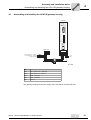
4.3
4
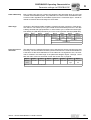
Assembling and installing the UOH11B gateway housing
UOH11B
DFP21B
RUN
BUS
FAULT
9
5
6
1
X30
20
21
22
23
0 1
24
25
26
AS
ADDRESS
H1
H2
X24
SEW Drive
X26
1234567
SC11 Systembus +, CAN high
SC12 Systembus -, CAN low
GND, CAN GND
+ 24 V
GND
58121BXX
X26
X26:1
SC11 system bus +, CAN high
X26:2
SC12 system bus, CAN low
X26:3
GND, CAN GND
X26:6
GND, CAN GND
X26:7
DC 24 V
The gateway housing has a power supply of DC 24V that is connected to X26.
Manual – DFP21B PROFIBUSDP-V1 Fieldbus Interface
19
Assembly and Installation Notes
Connection and terminal description of the DFP21B option
4
4.4
Connection and terminal description of the DFP21B option
Part number
PROFIBUS interface type DFP21B option: 824 240 2
The "PROFIBUS interface type DFP21B" option is only possible in conjunction with
MOVIDRIVE® MDX61B, not with MDX60B.
The DFP21B option must be plugged into the fieldbus slot.
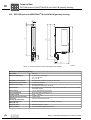
Front view of DFP21B
DFP21B
RUN
BUS
FAULT
9
5
6
1
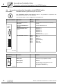
Description
DIP
switches
Terminal
Function
RUN: PROFIBUS operation
LED (green)
Indicates that the bus electronics are operating
correctly.
BUS FAULT: PROFIBUS error
LED (red)
Indicates PROFIBUSDP error.
ADDRESS: DIP switch for setting the PROFIBUS station
address
20
21
22
23
24
25
26
AS
Significance: 1
Significance: 2
Significance: 4
Significance: 8
Significance: 16
Significance: 32
Significance: 64
Autosetup for gateway operation
X30: PROFIBUS connection
X30:1
X30:2
X30:3
X30:4
X30:5
X30:6
X30:7
X30:8
X30:9
N.C.
N.C.
RxD/TxD-P
CNTR-P
DGND (M5V)
VP (P5V/100 mA)
N.C.
RxD/TxD-N
DGND (M5V)
X30
0 1
20
21
22
23
24
25
26
AS
ADDRESS
59110AXX
Front view of
MOVITRAC® B, DFP21B
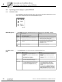
and UOH11B
Description
Function
H1
LED H1 (red)
System error (only for gateway functions)
H2
LED H2 (green)
Reserved
X24
X24 X terminal
RS-485 interface for diagnostics via PC and
MOVITOOLS® MotionStudio
(only applies to MOVITRAC® B)
58129axx
20
Manual – DFP21B PROFIBUSDP-V1 Fieldbus Interface
Assembly and Installation Notes
Pin assignment
4.5
4
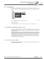
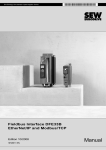
Pin assignment
Connection to the PROFIBUS network using a 9-pin sub D plug according to IEC 61158.
The T-bus connection must be made using a connector with the corresponding configuration.
[2]
1
6
9
5
R xD/TxD-P
R xD/TxD-N
CNTR -P
DGND (M5V)
VP (P 5V/100mA)
DGND (M5V)
3
8
4
5
6
9
[3]
[1]
06227AXX
Figure 4: Assignment of 9-pin sub D plug to IEC 61158
[1] 9-pin sub-D connector
[2] Signal line, twisted
[3] Conductive, wide area connection is necessary between the connector housing and the shield
4.5.1
MOVIDRIVE® / MOVITRAC® B / PROFIBUS connection
As a rule, the DFP21B option is connected to the PROFIBUS system using a shielded
twisted-pair cable. Observe the maximum supported transmission rate when selecting
the bus connector.
The twisted-pair cable is connected to the PROFIBUS connector at pin 3 (RxD/TxD-P)
and pin 8 (RxD/TxD-N). Communication takes place via these two contacts. The RS-485
signals RxD/TxD-P and RxD/TxD-N must be connected to the same contacts in all
PROFIBUS stations. Otherwise, no communication is possible via the bus medium.
The PROFIBUS interface sends a TTL control signal for a repeater or fiber optic adapter
(reference = pin 9) via pin 4 (CNTR-P).
4.5.2
Baud rates greater than 1.5 MBaud
The DFP21B option with baud rates > 1.5 MBaud can only be operated with special 12MBaud PROFIBUS connectors.
Manual – DFP21B PROFIBUSDP-V1 Fieldbus Interface
21
Assembly and Installation Notes
Shielding and routing bus cables
4
4.6
Shielding and routing bus cables
The PROFIBUS interface supports RS-485 transmission technology and requires the
cable type A to IEC 61158 as the physical medium for the PROFIBUS. This cable must
be a shielded, twisted-pair cable.
Correct shielding of the bus cable attenuates electrical interference that may occur in
industrial environments. The following measures ensure the best possible shielding:
•
Manually tighten the mounting screws on the connectors, modules, and equipotential
bonding conductors.
•
Use only connectors with a metal housing or a metallized housing.
•
Connect the shielding in the connector over a wide surface area.
•
Apply the shielding of the bus line on both ends.
•
Route signal and bus cables in separate cable ducts. Do not route them parallel to
power cables (motor leads).
•
In industrial environments, use metallic, grounded cable racks.
•
Route the signal cable and the corresponding equipotential bonding close to each
other using the shortest possible route.
•
Avoid using plug connectors to extend bus cables.
•
Route the bus cables closely along existing grounding surfaces.
In case of fluctuations in the ground potential, a compensating current may flow via the
bilaterally connected shield that is also connected to the protective earth (PE). In this
case, make adequate provision for equipotential bonding in accordance with the
relevant VDE regulations.
4.7
Bus termination
The DFP21B option is not provided with bus terminating resistors. This enables the bus
system to be put into operation more easily and reduces the number of error sources.
Use a plug with an integrated bus terminating resistor if the DFP21B option is at the
beginning or end of a PROFIBUS segment and only one PROFIBUS cable is leading to
the DFP21B.
Switch on the bus terminating resistors for this PROFIBUS connector.
22
Manual – DFP21B PROFIBUSDP-V1 Fieldbus Interface
Assembly and Installation Notes
Setting the station address
4.8
4
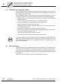
Setting the station address
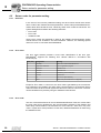
The PROFIBUS station address is set using DIP switches 20 to 26 on the option card.
MOVIDRIVE® supports the address range 1 to 125.
The default setting for the PROFIBUS station address is 4:
DFP21B
20 → Significance: 1 × 0 = 0
21 → Significance: 2 × 0 = 0
22 → Significance: 4 × 1 = 4
23 → Significance: 8 × 0 = 0
24 → Significance: 16 × 0 = 0
25 → Significance: 32 × 0 = 0
26 → Significance: 64 × 0 = 0
RUN
BUS
FAULT
9
5
6
1
X30
0 1
20
21
22
23
24
25
26
AS
ADDRESS
59110AXX
Any change made to the PROFIBUS station address during ongoing operation does not
take effect immediately. The change only comes into effect when the inverter is switched
on again (power supply + 24 V OFF/ON). The inverter displays the current station
address in fieldbus monitor parameter P092 "Fieldbus address" (display with DBG60B
or MOVITOOLS®/SHELL).
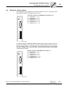
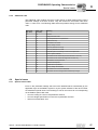
Example: Setting the PROFIBUS station address 17
DFP21B
20 → Significance: 1 × 1 = 1
21→ Significance: 2 × 0 = 0
22 → Significance: 4 × 0 = 0
23 → Significance: 8 × 0 = 0
24 → Significance: 16 × 1 = 16
25 → Significance: 32 × 0 = 0
26 → Significance: 64 × 0 = 0
RUN
BUS
FAULT
9
5
6
1
X30
20
21
22
23
0 1
24
25
26
AS
ADDRESS
59111AXX
Manual – DFP21B PROFIBUSDP-V1 Fieldbus Interface
23
Assembly and Installation Notes
Operating mode displays: option DFP21B
4
4.9
Operating mode displays: option DFP21B
4.9.1
PROFIBUS LEDs
The PROFIBUS interface DFP21B option card has 2 LEDs that indicate the current
status of the DFP21B option and the PROFIBUS system.
DFP21B
RUN
BUS
FAULT
58361AXX
RUN LED (green)
•
The RUN LED (green) indicates that the bus electronics are operating correctly
RUN
Cause of error
Green
•
PROFIBUS hardware OK.
–
Orange
•
The card is booting.
–
Off
•
Hardware defect in the bus electronics.
•
Switch the unit on again. Consult SEW
service if the error occurs again.
Flashes
2Hz
•
PROFIBUS address is set higher than 125
or to 0.
•
•
Use parameter P093 Fieldbus Address to
check the address set with the DIP
switches.
Reset the inverter.
•
The inverter is restarting.
Flashes
1Hz
LED BUS FAULT
(red)
•
•
Remedy
No error, only display.
The BUS FAULT LED (red) indicates a PROFIBUSDP fault.
BUS FAULT
Cause of error
Remedy
Red
•
Connection to the DP master has
dropped.
Unit does not detect a PROFIBUS baud
rate.
Possible bus interruption.
DP master not in operation.
•
•
•
•
•
•
Off
•
Unit is currently exchanging data with
the DP master (data exchange).
–
Flashing
•
Unit has detected the baud rate, but is
not being addressed by the DP master.
Unit was not configured in the DP
master or was configured incorrectly.
•
•
•
•
24
Check the PROFIBUSDP connection on
the unit.
Check the project planning of the DP
master.
Check all cables in your PROFIBUS DP
network.
Check the PROFIBUS address setting
on the DFP21B and in the project
planning software of the DP master.
Check the project planning of the DP
master.
Use the GSD file SEWA6003.GSD with
the identifier MOVIDRIVE®-DFP21B or
SEW_6009.GSD for gateway operation
with MOVITRAC® B for project planning.
Manual – DFP21B PROFIBUSDP-V1 Fieldbus Interface
Assembly and Installation Notes
Operating mode displays: option DFP21B
LEDs for gateway
communication
status
4
H1
H2
X24
58129axx
LED H1 Sys-fault (red)
Only for gateway function
Status
Status
Description
Red
System error
Gateway is not configured or one of the
drives is inactive.
Off
SBus ok
Gateway is configured correctly
Flashing
Bus scan
Bus is being checked by the gateway
LED H2 (green) is currently reserved.
X-terminal X24 is the RS-485 interface for diagnostics via PC and MOVITOOLS®
MotionStudio.
Manual – DFP21B PROFIBUSDP-V1 Fieldbus Interface
25
I
5
Project Planning and Startup
Validity of the GSD files for DFP21B
0
5
Project Planning and Startup
This section provides you with information on project planning for the DP master and
startup of the drive inverter for fieldbus operation.
Current versions of the GSD files for the DFP21B option are available on the SEW
homepage (http://www.sew-eurodrive.de) under the heading "Software". Both GSD files
can be used at the same time in one STEP7 project. Once you have downloaded and
unpacked the software, you will have two directories for the operating modes PROFIBUS DP and PROFIBUS DP-V1.
5.1
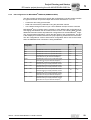
Validity of the GSD files for DFP21B
PROFIBUS option
DFP21B074 firmware option 1:
SEW_6003.GSD for DP
SEWA6003.GSD for DP-V1
SEW_6009.GSD for DP-V1
Gateway operation
824 399 9.10 and higher
ok
ok
No
1820 536 4.10 and higher
ok
ok
ok
Entries in the GSD file must not be changed or expanded. SEW assumes no liability for
inverter malfunctions caused by a modified GSD file.
5.2
DP master project planning the with MOVIDRIVE® GSD file
A GSD file is provided for project planning for the DP master. This file must be copied
into a special folder of your project planning software.
Refer to the manuals of the appropriate project planning software for details on the procedure.
5.2.1
GSD file for PROFIBUSDP
Use the GSD file SEW_6003.GSD from the "DP" directory if you want to use PROFIBUS DP communication to control the drive inverter. This GSD file corresponds to the
GSD revision1 and must be copied to a special directory of your project planning software. Refer to the manuals of the appropriate project planning software for details on
the procedure.
The unit master data files standardized by the PROFIBUS user group can be read by all
PROFIBUS DP masters.
26
Project planning tool
DP master
File name
All DP project planning tools to EN 50170 (V2)
For DP master
standard
SEW_6003.GSD
Siemens S7 hardware configuration
For all S7 DP masters
Siemens S5 COM PROFIBUS
For IM 308C etc.
Manual – DFP21B PROFIBUSDP-V1 Fieldbus Interface
Project Planning and Startup
DP master project planning the with MOVIDRIVE® GSD file
I
5
0
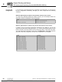
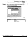
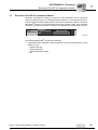
5.2.2
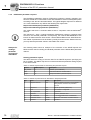
GSD file for PROFIBUS DP-V1
Use the GSD file SEWA6003.GSD from the "DP-V1" directory if you want to use the
parameter setting options of DP-V1 in addition to the standard PROFIBUS DP
communication to control the drive inverter.
This GSD file corresponds to GSD revision 3. If you use older, non-DP-V1-capable
PROFIBUS options, a connection is not established between the DP-V1 master and
DFP21B. In this case, the BUS FAULT LED of DFP21B remains switched on after the
DP-V1 master has started. The DP V1 master will indicate that the connection cannot
be established.
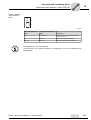
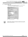
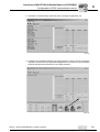
So that the GSD files are easy to identify, they are assigned the name for PROFIBUSDP-V1 and displayed in a special subdirectory in the project planning software for the
DP-V1 master (see following screenshot).
53545AXX
Manual – DFP21B PROFIBUSDP-V1 Fieldbus Interface
27
I
5
Project Planning and Startup
DP master project planning the with MOVIDRIVE® GSD file
0
5.2.3
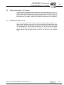
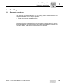
Project planning procedure
Proceed as follows for project planning for MOVIDRIVE® with PROFIBUS DP interface:
1. Read the README_GSDA6003.PDF file, which you receive with the GSD file for
further current information on project planning.
2. Install (copy) the GSD file according to the requirements of your project planning software. Once the file has been installed correctly, the device appears next to the slave
stations with the designation MOVIDRIVE®+DFP21.
3. Add the interface module under the name MOVIDRIVE®+DFP21 to the PROFIBUS
structure and assign the station address.
4. Select the process data configuration required for your application (see section 5.2.4
on page 29).
5. Enter the I/O or peripheral addresses for the configured data widths.
After project planning, you can start PROFIBUS DP. The red BUS FAULT LED indicates
the status of the project planning (OFF = project planning OK).
28
Manual – DFP21B PROFIBUSDP-V1 Fieldbus Interface
I
Project Planning and Startup
DP master project planning the with MOVIDRIVE® GSD file
5
0
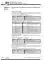
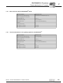
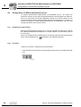
5.2.4
DP configuration for MOVIDRIVE® MDX61B (SEWA6003.GSD)
The drive inverter must be given a specific DP configuration by the DP master to define
the type and number of input and output data used for transmission. You can
•
Control the drive using process data
•
Read and write all drive parameters using the parameter channel
•
Use a data exchange medium of your choice between IPOSplus and the controller
MOVIDRIVE® drive inverters make it possible to have different DP configurations for
exchanging data between the DP master and the inverter. The following table provides
additional information about all possible DP configurations for the MOVIDRIVE® range.
The "Process data configuration" column lists the names of the configurations. This text
is also displayed as selection list within the project planning software for the DP master.
The "DP configurations" column shows which configuration data is sent to the inverter
when the PROFIBUS DP connection is being established.
Process data
configuration
Meaning / notes
1 PD
MOVIDRIVE® control via 1 process data word
®
DP configuration
0
1
F0hex
-
2 PD
MOVIDRIVE control via 2 process data words
F1hex
-
3 PD
MOVIDRIVE® control via 3 process data words
F2hex
-
6 PD
MOVIDRIVE®
control via 6 process data words
(PD4-PD6 can only be used with IPOSplus® )
0hex
F5hex
10 PD
MOVIDRIVE® control via 10 process data words
(PD4-PD10 can only be used with IPOSplus® )
0hex
F9hex
Param + 1 PD
MOVIDRIVE® control via 1 process data word
Parameter setting via 8 byte parameter channel
F3hex
F0hex
Param + 2 PD
MOVIDRIVE® control via 2 process data words
Parameter setting via 8 byte parameter channel
F3hex
F1hex
Param + 3 PD
MOVIDRIVE® control via 3 process data words
Parameter setting via 8 byte parameter channel
F3hex
F2hex
Param + 6 PD
MOVIDRIVE® control via 6 process data words
Parameter setting via 8 byte parameter channel
(PD4-PD10 can only be used with IPOSplus® )
F3hex
F5hex
Param + 10 PD
MOVIDRIVE® control via 10 process data words
Parameter setting via 8 byte parameter channel
(PD4-PD10 can only be used with IPOSplus® )
F3hex
F9hex
Manual – DFP21B PROFIBUSDP-V1 Fieldbus Interface
29
5
I
Project Planning and Startup
DP master project planning the with MOVIDRIVE® GSD file
0
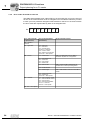
Universal DP
configuration
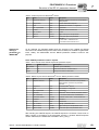
If you select the "Universal Module" DP configuration (S7 HWConfig), you can structure
the DP configuration individually, although you must comply with the following
conditions.
Module 0 (DP identifier 0) defines the parameter channel of the inverter.
To ensure the parameter settings are made correctly, you must always transfer the
parameter channel consistently for the entire length.
Length
Function
0
Parameter channel deactivated
8 I/O bytes or 4 I/O words
Parameter channel is used
Module 1 (DP identifier 1) defines the process data channel of the inverter.
In addition to the process data configuration predefined in the GSD file, you can also
specify the process data configuration with 4, 5, 7, 8 and 9 process data words. Ensure
that the number of input and output words is always the same. If the lengths are different, data cannot be exchanged. In this case, the BUS FAULT LED flashes and the
parameter P090 PD Configuration indicates the configuration error with 0PD.
Length
30
Function
2 I/O bytes or 1 I/O word
1 process data word
4 I/O bytes or 2 I/O words
2 process data words
6 I/O bytes or 3 I/O words
3 process data words
8 I/O bytes or 4 I/O words
4 process data words
10 I/O bytes or 5 I/O words
5 process data words
12 I/O bytes or 6 I/O words
6 process data words
14 I/O bytes or 7 I/O words
7 process data words
16 I/O bytes or 8 I/O words
8 process data words
18 I/O bytes or 9 I/O words
9 process data words
20 I/O bytes or 10 I/O words
10 process data words
Manual – DFP21B PROFIBUSDP-V1 Fieldbus Interface
I
Project Planning and Startup
DP master project planning the with MOVIDRIVE® GSD file
5
0
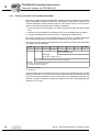
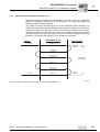
The following figure shows the structure of the configuration data defined in EN 50170
(V2). This configuration data is transmitted to the drive inverter during the initial start of
the DP master.
7 / MSB
6
5
4
3
2
1
0 / LSB
Data length
0000 = 1 byte/word
1111 = 16 bytes/words
Input / output
00 = Special identifier formats
01 = Input
10 = Output
11 = Input / output
Format
0 = Byte structure
1 = Word structure
Integrity over
0 = Byte or word
1 = Entire length
Note:
MOVIDRIVE® does not support the "Special identifier formats" coding.
Only use the "Integrity over entire length" setting for data transmission.
Data integrity
Consistent data is data that has to be transmitted between the programmable controller
and the drive inverter as one block at all times and must never be transmitted separately.
Data integrity is especially important for the transmission of positioning values or
complete positioning tasks. Inconsistent transmission may contain data from different
program cycles of the automation device. This would lead to undefined values being
transmitted to the drive inverter.
For PROFIBUS DP, data communication between the programmable controller and
drive engineering devices is usually carried out with the setting "Data integrity over
entire length".
Manual – DFP21B PROFIBUSDP-V1 Fieldbus Interface
31
I
5
Project Planning and Startup
DP master project planning the with MOVIDRIVE® GSD file
0
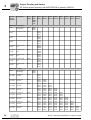
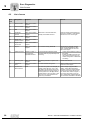
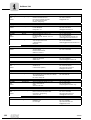
5.2.5
MOVIDRIVE® MDX61B external diagnostics
For MOVIDRIVE® MDX61B drive inverters with option DFP21B, it is possible to activate
automatic generation of external diagnostic alarms via PROFIBUS DP during the project
planning in the DP master. If this function has been activated, the inverter sends an
external diagnostic signal to the DP master every time a malfunction occurs. You then
have to program corresponding algorithms in the program of the DP master system to
evaluate the diagnostic information. These algorithms can be quite complex.
Recommendation
It is not always necessary to activate the external diagnostic function because
MOVIDRIVE® transmits the current drive status via status word 1 during every
PROFIBUS DP cycle.
The structure of the unit-specific diagnostics was redefined for PROFIBUS DP-V1. The
mechanism described here can only be used with PROFIBUS DP (without DP-V1
expansions). We recommend that you do not use this mechanism for new applications.
Note for SIMATIC S7 master systems:
Diagnostic alarms may also be triggered by the PROFIBUS DP system in the DP master
even if external diagnostic generation is deactivated. As a result, the corresponding
operating blocks (such as OB84 for S7-400 and OB82 for S7-300) should always be
created in the controller.
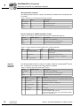
Procedure
Additional application-specific parameters can be defined in every DP master during
project planning for a DP slave. These parameters are transferred to the slave when the
PROFIBUS DP starts up. Nine application-specific parameter data items are provided
for MOVIDRIVE® with the following functions:
Byte:
Permitted
value
Function
0
00 hex
Reserved for DP-V1
1
00 hex
Reserved for DP-V1
2
00 hex
Reserved for DP-V1
3
06 hex
Structured user parameter block with a length of 6 bytes
4
81 hex
Structure type: User (proprietary)
5
00 hex
Slot number: 0 = complete unit
6
00 hex
Reserved
7
01 hex
SEW user parameter version: 1
8
00 hex
01 hex
DFP21 generates a diagnostic alarm when a malfunction occurs.
DFP21 does not generate a diagnostic alarm when a malfunction occurs
(factory setting).
Values not listed here are not permitted as they can cause malfunctions in the DFP21B.
32
Manual – DFP21B PROFIBUSDP-V1 Fieldbus Interface
I
Project Planning and Startup
DP master project planning the with MOVIDRIVE® GSD file
5
0
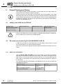
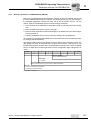
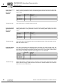
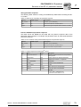
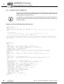
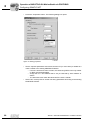
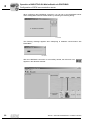
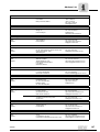
Project planning
example
The project planning programs of the DP master systems either offer the option of
activating the external diagnostics in plain text format, such as with STEP7 (Figure 5),
or of stating the information directly in hex code.
50256AXX
Figure 5: Activating external diagnostics with STEP7
Parameter data (hex)
Function
00, 00, 00, 06, 81, 00, 00, 01, 00
Diagnostic alarms are generated even in case of an error
(enabled = on)
00, 00, 00, 06, 81, 00, 00, 01, 01
Diagnostic alarms are not generated if there is an error
(disabled = off, factory setting)
Manual – DFP21B PROFIBUSDP-V1 Fieldbus Interface
33
I
5
Project Planning and Startup
DP master project planning with MOVITRAC® or gateway GSD file
0
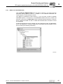
5.3
DP master project planning with MOVITRAC® or gateway GSD file
This section provides information on project planning for the PROFIBUS DP master with
MOVITRAC® B and DFP21B gateway / UOH11B.
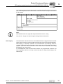
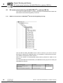
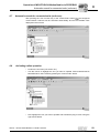
5.3.1
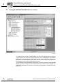
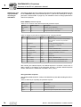
GSD files for operation in MOVITRAC® B and UOH11B gateway housing
11328AEN
Use the GSD file SEW_6009.GSD from the "DPV1" directory if you want to use the
DFP21B as a gateway from PROFIBUS DP-V1 on the SBus to control the drive inverter.
This GSD file corresponds to GSD revision 5.
Refer to the manuals of the appropriate project planning software for details on the
procedure.
The unit master data files standardized by the PROFIBUS user group can be read by all
PROFIBUS DP masters.
34
Project planning tool
DP master
File name
All DP project planning tools to
EN50170 (V2)
for DP master standard
SEW_6009.GSD
Siemens S7 hardware configuration
for all S7 DP masters
Manual – DFP21B PROFIBUSDP-V1 Fieldbus Interface
Project Planning and Startup
DP master project planning with MOVITRAC® or gateway GSD file
I
5
0
5.3.2
PROFIBUSDP master startup
Supporting files for DFP21B gateway are available in the Internet at http://www.seweurodrive.de.
•
Observe the notes in the README.TXT file on the GSD disk.
•
Install the GSD file according to the requirements of the project planning software for
the DP master. After successful installation, the "DFP21B gateway" device appears
in the list of slave stations.
•
Insert the interface module into the PROFIBUS structure under the name "DFP21BGateway" and assign the PROFIBUS address.
•
Select the process data configuration required for your application (see section 5.3.3
on page 36).
•
Enter the I/O or peripheral addresses for the projected data widths.
•
Save the configuration.
•
Add data exchange with the fieldbus interface to your application program. For S7,
use the system functions for consistent data exchange for this purpose (SFC14 and
SFC15).
•
The BUS FAULT LED at the fieldbus interface should extinguish after you have
saved the project, loaded it in the DP master and started the DP master. If this is not
the case, check the connections and terminating resistors of the PROFIBUS and the
project planning, especially the PROFIBUS address.
Manual – DFP21B PROFIBUSDP-V1 Fieldbus Interface
35
I
5
Project Planning and Startup
DP master project planning with MOVITRAC® or gateway GSD file
0
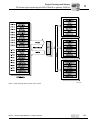
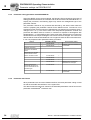
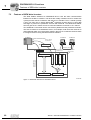
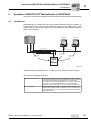
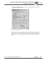
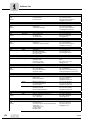
5.3.3
Configuration of the PROFIBUSDP interface
General
The inverter must be given a specific DP configuration by the DP master to define type
and number of input and output data used for the transmission. You can control the
drives via process data and read and write all parameters of the fieldbus interface via
the parameter channel.
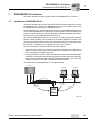
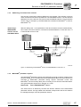
The figure shows a schematic view of the data exchange between automation device
(DP-V1 master), fieldbus interface (DP-V1 slave) and an inverter with process data
channel and parameter channel.
C1-Master
C2-Master
Acyclic DP-V1
C2-Services
Cyclic OUT Data
Param
PD
Param
C2-Master
PROFIBUS DP-V1
PD
Cyclic IN Data
Acyclic DP-V1
C1-Services
Acyclic DP-V1
C2-Services
DFP 21B
RUN
BUS
FAULT
0
1
20
21
22
23
MOVITRAC® B
Unit = SBus-Address:
EURODRIVE
ADDRESS
Unit = 3
1
2
EURODRIVE
Unit = 5
X30
Unit = 1
Unit = 0
24
25
26
nc
Unit = 0
3
EURODRIVE
4
EURODRIVE
5
EURODRIVE
Unit = 8
6
EURODRIVE
7
EURODRIVE
8
EURODRIVE
59093AXX
Figure 6: Data exchange with parameter data (Param) and process data (PD)
36
Manual – DFP21B PROFIBUSDP-V1 Fieldbus Interface
Project Planning and Startup
DP master project planning with MOVITRAC® or gateway GSD file
I
5
0
Configuration of
the process data
The fieldbus interface allows for different DP configurations for the data exchange
between DP master and fieldbus interface. The following table provides additional
details on all standard DP configurations of the fieldbus interfaces. The "Process data
configuration" column lists the names of the configurations. This text is also displayed
as selection list within the project planning software for the DP master. The DP configurations column shows the type of configuration data sent to the fieldbus interface while
the link to PROFIBUS DP is being established. The configurations are determined by
the default process data width for SEW inverters of 3 process data words. The fieldbus
interface then distributes these process data words to the individual units. The parameter channel is used for setting the parameters of the DFP21B and is not passed on to
the connected stations. The fieldbus interface accepts between 1 to 24 process data
words with and without parameter channel.
The standard entries of the GSD file are based on the DFP21B Autosetup operating
mode and allow process data widths of 3PD to 24PD corresponding to 1 to 8 inverters
connected to the fieldbus interface.
3 PDs are always assigned to any SBus station.
ONE module for all
drives
The process data is transmitted in one consistent data block for all inverters connected
to the fieldbus interface. Thus, only system functions SFC14 and SFC15 need to be
called in STEP7.
One module per
drive
One consistent data block exists for each connected inverter. On the controller, this
corresponds to the existing setup of several inverters with their own fieldbus interface.
System functions SFC14 and SFC15 need to be called for each inverter in STEP7.
Drive parameters of connected MOVITRAC® B inverters can only be accessed using the
DP-V1 parameter services.
Manual – DFP21B PROFIBUSDP-V1 Fieldbus Interface
37
I
5
Project Planning and Startup
DP master project planning with MOVITRAC® or gateway GSD file
0
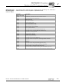
Process
data configuration
Description
Slot 1
Slot 2
Slot 3
Slot 4
Slot 5
Slot 6
Slot 7
Slot 8
Slot 9
Slot 10
Empty
Parameter
channel
Drive 1
Drive 2
Drive 3
Drive 4
Drive 5
Drive 6
Drive 7
Drive 8
C0hex,
87hex,
87hex
ONE module for all drives
Param
8 byte parameter channel
00hex
AS 1 Drive
(3 PD)
Control via 3 PD
00hex
C0hex,
C2hex,
C2hex
AS 2 Drives
(6 PD)
Control via 6 PD
00hex
C0hex,
C5hex,
C5hex
AS 3 Drives
(9 PD)
Control via 9 PD
00hex
C0hex,
C8hex,
C8hex
AS 4 Drives
(12 PD)
Control via 12
PD
00hex
C0hex,
CBhex,
CBhex
AS 5 Drives
(15 PD)
Control via 15
PD
00hex
C0hex,
CEhex,
CEhex
AS 6 Drives
(18 PD)
Control via 18
PD
00hex
C0hex,
D1hex,
D1hex
AS 7 Drives
(21 PD)
Control via 21
PD
00hex
C0hex,
D4hex,
D4hex
AS 8 Drives
(24 PD)
Control via 24
PD
00hex
C0hex,
D7hex,
D7hex
ONE module per drive
38
Param
8 byte parameter channel
00hex
C0hex,
87hex,
87hex
AS 1 Drive
(1 x 3 PD)
Control via
1x3 PD
00hex
C0hex,
C2hex,
C2hex
AS 2 Drives
(2 x 3 PD)
Control via
2x3 PD
00hex
C0hex,
C2hex,
C2hex
C0hex,
C2hex,
C2hex
AS 3 Drives
(3 x 3 PD)
Control via
3x3 PD
00hex
C0hex,
C2hex,
C2hex
C0hex,
C2hex,
C2hex
C0hex,
C2hex,
C2hex
AS 4 Drives
(4 x 3 PD)
Control via
4x3 PD
00hex
C0hex,
C2hex,
C2hex
C0hex,
C2hex,
C2hex
C0hex,
C2hex,
C2hex
C0hex,
C2hex,
C2hex
AS 5 Drives
(5 x 3 PD)
Control via
5x3 PD
00hex
C0hex,
C2hex,
C2hex
C0hex,
C2hex,
C2hex
C0hex,
C2hex,
C2hex
C0hex,
C2hex,
C2hex
C0hex,
C2hex,
C2hex
AS 6 Drives
(6 x 3 PD)
Control via
6x3 PD
00hex
C0hex,
C2hex,
C2hex
C0hex,
C2hex,
C2hex
C0hex,
C2hex,
C2hex
C0hex,
C2hex,
C2hex
C0hex,
C2hex,
C2hex
C0hex,
C2hex,
C2hex
AS 7 Drives
(7 x 3 PD)
Control via
7x3 PD
00hex
C0hex,
C2hex,
C2hex
C0hex,
C2hex,
C2hex
C0hex,
C2hex,
C2hex
C0hex,
C2hex,
C2hex
C0hex,
C2hex,
C2hex
C0hex,
C2hex,
C2hex
C0hex,
C2hex,
C2hex
AS 8 Drives
(8 x 3 PD)
Control via
8x3 PD
00hex
C0hex,
C2hex,
C2hex
C0hex,
C2hex,
C2hex
C0hex,
C2hex,
C2hex
C0hex,
C2hex,
C2hex
C0hex,
C2hex,
C2hex
C0hex,
C2hex,
C2hex
C0hex,
C2hex,
C2hex
C0hex,
C2hex,
C2hex
Manual – DFP21B PROFIBUSDP-V1 Fieldbus Interface
Project Planning and Startup
DP master project planning with MOVITRAC® or gateway GSD file
I
5
0
"Universal module"
DP configuration
Module 0 must always be pre-assigned to 0x00.
The "Universal Module" (such as in STEP7) allows you to set the parameters of the fieldbus interface deviating from the preset standard values of the GSD file. This is useful if
you want to operate several inverters with different process data words at the fieldbus
interface, for example.
You must observe the following conditions:
Operating mode
(DP-V1 mode)
•
Module 1 defines the parameter channel of the inverter. Entering 0 will switch off the
parameter channel; entering 0xC0 0x87 0x87 will switch on the parameter channel
with 8 bytes length.
•
The following modules determine the process data width of the fieldbus interface at
the PROFIBUS. The added process data width of all following modules must be
between 1 and 24 words. For safety reasons, the modules must be listed with data
integrity. Ensure that an inverter connected to the fieldbus interface is represented
by such a consistent module entry.
•
Only the special identifier format is permitted.
The DP-V1 operating mode can usually be activated during project planning for a C1
master. All DP slaves, which have the DP-V1 functions enabled in their GSD files and
which support DP-V1, will then be operated in the DP-V1 mode. Standard DP slaves will
still to run via PROFIBUS DP. This ensures mixed mode is run for DP-V1 and DPcapable modules. Depending on the specification of the master functionality, a DP-V1capable station, that was configured using the DP-V1 GSD file, can run in the "DP"
operating mode.
Manual – DFP21B PROFIBUSDP-V1 Fieldbus Interface
39
I
5
Project Planning and Startup
DP master project planning with MOVITRAC® or gateway GSD file
0
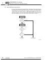
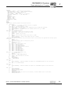
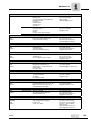
5.3.4
Autosetup for gateway operation
The Autosetup function enables startup of the DFP21B as gateway to be performed
without a PC. Activate the function via the Autosetup DIP switch (see section 4.4 on
page 20).
Switching on the Autosetup DIP switch causes the function to be performed once. The
Autosetup DIP switch must then remain in the ON position. The function can be
performed again by switching the DIP switch off and back on again.
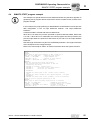
As a first step, the DFP21B searches for drive inverters on the SBus below its hierarchical level. This process is indicated by the H1 LED (system fault) flashing briefly. Different
SBus addresses must be set for the drive inverters (P813). We recommend assigning
the addresses beginning with address 1 in ascending order based on the arrangement
of inverters in the control cabinet. The process image on the fieldbus side is expanded
by three words for each detected drive inverter.
The H1 LED remains lit if no drive inverter was located. A total of up to eight drive inverters is taken into account. The following figure shows the process image for three drive
inverters with three words each of process output data and process input data.
Following the search, the DFP21B cyclically exchanges 3 process data words with each
connected drive inverter. The process output data is fetched from the fieldbus, divided
into blocks of three and transmitted. The drive inverters read the process input data, put
them together and send them to the fieldbus master.
The cycle time of the SBus communication requires 2 ms for each station.
This means the cycle time of the process data update is 8x2 ms=16 ms for an application
with 8 inverters on the SBus.
If you change the process data assignment of the drive inverters connected to the
DFP21B, you have to activate Autosetup again because the DFP21B saves these
values only once during Autosetup. At the same time, the process data assignments of
the connected drive inverters may not be changed dynamically after Autosetup.
40
Manual – DFP21B PROFIBUSDP-V1 Fieldbus Interface
Project Planning and Startup
DP master project planning with MOVITRAC® or gateway GSD file
I
5
0
DFP
59442AXX
Figure 7: Data exchange DP-V1 master DFP inverter
Manual – DFP21B PROFIBUSDP-V1 Fieldbus Interface
41
I
5
Project Planning and Startup
Setting the MOVIDRIVE® MDX61B drive inverter
0
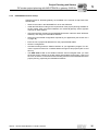
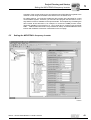
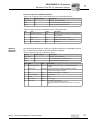
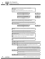
5.4
Setting the MOVIDRIVE® MDX61B drive inverter
11330AEN
To control the drive inverter via PROFIBUS, you must first switch the drive inverter to
control signal source (P101) and setpoint source (P100) = FIELDBUS. The FIELDBUS
setting means the drive inverter parameters are set for acceptance of setpoints via
PROFIBUS. The MOVIDRIVE® drive inverter then responds to the process output data
transmitted from the master programmable controller.
The parameters of the MOVIDRIVE® drive inverter can be set right away via PROFIBUS
without any further settings once the PROFIBUS option card has been installed. For
example, all parameters can be set by the master programmable controller after being
switched on.
42
Manual – DFP21B PROFIBUSDP-V1 Fieldbus Interface
Project Planning and Startup
Setting the MOVITRAC® frequency inverter
I
5
0
Activation of the control signal source and setpoint source FIELDBUS is signaled to the
machine control using the "Fieldbus mode active" bit in the status word.
For safety reasons, you must also enable the drive inverter at the terminals for control
via the fieldbus system. Therefore, you must wire and program the terminals in such a
way that the inverter is enabled via the input terminals. The simplest way of enabling the
drive inverter at the terminals is, for example, to connect the DIØØ (function /CONTROLLER INHIBIT) input terminal to a +24-V signal and to program input terminals
DIØ1 ... DIØ3 to NO FUNCTION. The procedure for startup of the MOVIDRIVE® drive
inverter with a fieldbus connection is described on the next page.
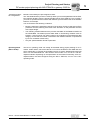
5.5
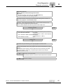
Setting the MOVITRAC® frequency inverter
11329AEN
Manual – DFP21B PROFIBUSDP-V1 Fieldbus Interface
43
5
I
Project Planning and Startup
Setting the MOVITRAC® frequency inverter
0
To control the drive inverter via PROFIBUS, you must first switch the drive inverter to
control signal source (P101) and setpoint source (P100) = SBus. The SBus setting
means the drive inverter parameters are set for control and setpoint entry via gateway.
The MOVITRAC® drive inverter then responds to the process output data transmitted
from the master programmable controller.
It is necessary to set the SBus1 timeout interval (P815) to a value other than 0 ms for
the MOVITRAC® frequency inverter to stop if faulty SBus communication is encountered. We recommend a value in the range 50 to 200 ms.
Activation of the control signal source and setpoint source SBus is signaled to the
machine control using the "SBus mode active" bit in the status word.
For safety reasons, you must also enable the drive inverter at the terminals for control
via the fieldbus system. Therefore, you must wire and program the terminals in such a
way that the inverter is enabled via the input terminals. The simplest way of enabling the
drive inverter at the terminals is, for example, to connect the DI1 (function CW/STOP)
input terminal to a +24-V signal and to program the remaining input terminals to NO
FUNCTION.
Set the parameter P881 SBus address to values between 1 to 8 in ascending order.
The SBus address 0 is used by DFP21B gateway and therefore must not be used.
Set P883 SBus timeout to values between 50 to 200 ms.
44
Manual – DFP21B PROFIBUSDP-V1 Fieldbus Interface
I
PROFIBUSDP Operating Characteristics
Controlling the MOVIDRIVE® MDX61B drive inverter
6
0
6
PROFIBUSDP Operating Characteristics
This section describes the basic characteristics of the drive inverter with PROFIBUS DP.
Controlling the MOVIDRIVE® MDX61B drive inverter
6.1
The drive inverter is controlled via the process data channel, which is up to 10 I/O words
in length. These process data words may be mapped in the I/O or peripheral area of the
control if a programmable control is used as DP master and can be addressed as usual.
PA 3
PA 2
PA 1
[1]
PA 1
PA 2
PA 3
PA 10
[1]
PE 1
PE 2
PE 3
PE 10
[2]
PW160
PW158
PW156
PW154
PW152
PW150
PW148
MOVIDRIVE® B
PW160
PW158
PW156
PW154
PW152
PW150
PW148
PE 3
PE 2
PE 1
58688AXX
Figure 8: Mapping PROFIBUS data in the PLC address range
[1]
8-byte MOVILINK® parameter channel
[2]
PLC address range
PE1 ... PE10
Process input data
PA1 ... PO10 Process output data
•
For additional information on programming and project planning, refer to the
README_GSDA6003.PDF file included in the GSD file.
•
For more information about controlling via the process data channel, in particular
regarding the coding of the control and status word, refer to the Fieldbus Unit Profile
manual.
Manual – DFP21B PROFIBUSDP-V1 Fieldbus Interface
45
I
6
PROFIBUSDP Operating Characteristics
Controlling the MOVIDRIVE® MDX61B drive inverter
0
6.1.1
Control example for SIMATIC S7 with MOVIDRIVE® MDX61B
The drive inverter is controlled using SIMATIC S7 in accordance with the selected
process data configuration either directly using load and transfer commands or by
means of special system functions, SFC 14 DPRD_DAT and SFC15 DPWR_DAT.
S7 data lengths of 3 bytes or more than 4 bytes must always be transmitted using
system functions SFC14 and SFC15.
Consequently, the data in the following table applies:
6.1.2
Process data configuration
STEP7 access via
1 PD
Load / transfer commands
2 PD
Load / transfer commands
3 PD
System functions SFC14/15 (length: 6 bytes)
6 PD
System functions SFC14/15 (length: 12 bytes)
10 PD
System functions SFC14/15 (length: 20 bytes)
Param + 1 PD
Parameter channel: System functions SFC14/15 (length: 8 bytes)
Process data: Load / transfer commands
Param + 2 PD
Parameter channel: System functions SFC14/15 (length: 8 bytes)
Process data: Load / transfer commands
Param + 3 PD
Parameter channel: System functions SFC14/15 (length: 8 bytes)
Process data: System functions SFC14/15 (length: 6 bytes)
Param + 6 PD
Parameter channel: System functions SFC14/15 (length: 8 bytes)
Process data: System functions SFC14/15 (length: 12 bytes)
Param + 10 PD
Parameter channel: System functions SFC14/15 (length: 8 bytes)
Process data: System functions SFC14/15 (length: 20 bytes)
PROFIBUSDP timeout (MOVIDRIVE® MDX61B)
If the data transfer via PROFIBUS DP is faulty or interrupted, the response monitoring
time in MOVIDRIVE® elapses (if configured in the DP master). The BUS-FAULT LED
lights up or flashes to indicate that no new user data is being received. At the same time,
MOVIDRIVE® performs the fault response selected with P831 Fieldbus timeout
response.
P819 Fieldbus timeout displays the response monitoring time specified by the DP
master during the PROFIBUS DP startup. The timeout can only be changed via the DP
master. Although modifications made using the keypad or MOVITOOLS® are displayed,
they do not have any effect and are overwritten when the DP is next started up.
6.1.3
Fieldbus timeout response (MOVIDRIVE® MDX61B)
P831 is used to set the parameters for the fault response, which is triggered by the fieldbus timeout monitoring. The setting made here must correspond to the setting in the
master system (S7: response monitoring).
46
Manual – DFP21B PROFIBUSDP-V1 Fieldbus Interface
PROFIBUSDP Operating Characteristics
Control of the MOVITRAC® inverter (gateway)
I
6
0
6.2
Control of the MOVITRAC® inverter (gateway)
The inverter is controlled via the process data channel, which is up to 3 I/O words in
length. These process data words are reproduced in the I/O or peripheral area of the
controller, for example when a programmable logic controller is used as the DP master.
As a result, they can be addressed in the usual manner.
[1]
[2]
POW318
POW316
POW314
POW312
POW310
POW308
PO 3
PO 2
PO 1
PO 3
PO 2
PO 1
PO 1 PO 2 PO 3 PO 1 PO 2 PO 3
MOVITRAC® B 1
PI 1
PIW318
PIW316
PIW314
PIW312
PIW310
PIW308
PI 2
PI 3
MOVITRAC® B 2
PI 1
PI 2
PI 3
PI 3
PI 2
PI 1
PI 3
PI 2
PI 1
58612AXX
Figure 9: Mapping PROFIBUS data in the PLC address range
[1]
Address range MOVITRAC® B, device 2
[2]
Address range MOVITRAC® B, device 1
PO = process output data / PI = process input data
Additional information on programming and project planning can be found in the
README_GSD6009.PDF file included in the GSD file.
Manual – DFP21B PROFIBUSDP-V1 Fieldbus Interface
47
I
6
PROFIBUSDP Operating Characteristics
Control of the MOVITRAC® inverter (gateway)
0
6.2.1
Control example for SIMATIC S7 with MOVITRAC® B (gateway)
The drive inverter is controlled via SIMATIC S7 depending on the selected process data
configuration, either directly via load and transfer commands or via the special system
functions SFC 14 DPRD_DAT and SFC15 DPWR_DAT.
S7 data lengths of 3 bytes or more than 4 bytes must always be transmitted using
system functions SFC14 and SFC15.
STEP7 program
example
6.2.2
Process data configuration
STEP7 access via
3 PD...24 PD
System functions SFC14/15
(length: 6...48 bytes)
Param + 3 PD...24 PD
System functions SFC14/15
(length 6...48 bytes for PD + 8 bytes for parameter)
The "README_GSD6009.PDF" file contains project planning and programming
examples for SIMATIC S7. See also section 6.4 on page 55.
SBus timeout
If one or more drive inverters on the SBus can no longer be addressed by the DFP21,
the gateway enters error code F11 System fault, in status word 1 of the corresponding
drive inverter. The H1 LED (system fault) lights up, and the fault is also displayed via the
diagnostics interface. It is necessary to set the SBus timeout interval (P815) of the
MOVITRAC® B system error to a value other than 0 for the drive inverter to stop. The
error resets itself in the gateway. In other words, the current process data is exchanged
immediately after restarting the communication.
6.2.3
Unit faults
The gateways detect a series of faults during the self test and respond by locking themselves. The exact error responses and remedies can be found in the list of errors. A
hardware defect causes error F111 system fault to be displayed on the fieldbus process
input data for status words 1 of all drive inverters. The H1 LED (system fault) at the
DFP21B then flashes at regular intervals. The exact error code is displayed in the status
of the gateway using MOVITOOLS® MotionStudio on the diagnostic interface.
48
Manual – DFP21B PROFIBUSDP-V1 Fieldbus Interface
PROFIBUSDP Operating Characteristics
Parameter settings via PROFIBUS DP
I
6
0
6.2.4
Fieldbus timeout of the DFP21B in gateway operation
You can set how the gateway should respond in case of timeout using the P831 Fieldbus
timeout response parameter.
6.3
No response
The drives on the subordinate SBus continue with the last setpoint value.
These drives cannot be controlled when the PROFIBUS communication is interrupted.
PA_DATA=0
The rapid stop is activated for all drives that have a process data configuration
with control word 1 or 2 when a PROFIBUS timeout is detected. For this
purpose, the gateway sets the bits 0 to 2 of the control word to 0.
The drives are stopped with the rapid stop ramp.
Parameter settings via PROFIBUS DP
With PROFIBUS DP, the drive parameters are accessed via the 8-byte MOVILINK®
parameter channel. This channel offers extra parameter services in addition to the
conventional READ and WRITE services.
The inverter parameter settings via the PROFIBUS DP parameter channel can only be
used for MOVIDRIVE® MDX61B and the parameters of the DFP21B gateway.
The PROFIBUS DP parameter channel does not provide data access to the parameters
of the inverter that are installed below the gateway at the SBus.
6.3.1
Structure of the 8-byte MOVILINK® parameter channel
PROFIBUS DP enables access to the inverter drive parameters via the "Parameter
process data object" (PPO). This PPO is transmitted cyclically and contains the process
data channel [2] and a parameter channel [1] that can be used to exchange acyclical
parameter values.
[1]
[2]
[1]
[2]
53492AXX
Figure 10: Communication via PROFIBUS DP
Manual – DFP21B PROFIBUSDP-V1 Fieldbus Interface
49
6
I
PROFIBUSDP Operating Characteristics
Parameter settings via PROFIBUS DP
0
The following table shows the structure of the 8-byte MOVILINK® parameter channel.
Essentially, the parameter channel is made up of a management byte, an index word, a
reserved byte and four data bytes.
Byte 0
Management
Management of
the 8-byte
MOVILINK®
parameter
channel
Byte 1
Subindex
Byte 2
Byte 3
Byte 4
Byte 5
Byte 6
Byte 7
Index high
Index low
MSB data
Data
Data
LSB data
Parameter index
4 byte data
The entire procedure for setting parameters is coordinated using management byte 0.
This byte provides important service parameters such as service identifier, data length,
version and status of the service performed. The following table shows that bits 0, 1, 2
and 3 contain the service identifier, and define which service is performed. Bit 4 and bit
5 specify the data length in bytes for the WRITE service. This should be set to 4 bytes
for all SEW drive inverters.
7 / MSB
6
5
4
3
2
1
0 / LSB
Service identifier
0000 = No service
0001 = READ parameter
0010 = WRITE parameter
0110 = READ default
0111 = READ scale
1000 = READ attribute
Data length
00 = 1 byte
01 = 2 bytes
10 = 3 bytes
11 = 4 bytes (must be set)
Handshake bit
Must be changed on every new task in cyclical transmission.
Status bit
0 = No error during service execution
1 = Error during service execution
Bit 6 is used as a handshake between the control and the drive inverter. It triggers the
implementation of the transferred service in the drive inverter. In PROFIBUS DP. the
parameter channel is transmitted cyclically with the process data. For this reason, the
implementation of the service in the drive inverter must be triggered by edge control
using the handshake bit 6. For this purpose, the value of this bit is altered for each new
service that is to be executed. The drive inverter uses the handshake bit to signal
whether the service has been executed or not. The service was executed if the handshake bit received in the control is identical with the transmitted handshake bit. Status
bit 7 indicates whether it was possible to execute the service properly or if errors
occurred.
50
Manual – DFP21B PROFIBUSDP-V1 Fieldbus Interface
I
PROFIBUSDP Operating Characteristics
Parameter settings via PROFIBUS DP
6
0
Index addressing
Byte 2 (Index high) and byte 3 (Index low) determine the parameter which is to be read
or written via the fieldbus system. The parameters of a drive inverter are addressed with
a uniform index regardless of the fieldbus system that is connected. Byte 1 should be
viewed as reserved and must always be set to 0x00.
Data range
As shown in the following table, the data is contained in bytes 4 through 7 of the parameter channel. This means up to 4 bytes of data can be transmitted per service. The data
is always entered with right-justification. In other words, byte 7 contains the least significant data byte (LSB data) whereas byte 4 is the most significant data byte (MSB data).
Byte 0
Byte 1
Byte 2
Byte 3
Byte 4
Byte 5
Byte 6
Byte 7
Management
Subindex
Index high
Index low
MSB data
Data
Data
LSB data
High byte 1
Low byte 1
High byte 2
Low byte 2
High word
Low word
Double word
Incorrect service
execution
The status bit in the management byte is set to signal that a service has been executed
incorrectly. The service was executed by the drive inverter if the received handshake bit
is the same as the sent handshake bit. If the status bit now signals an error, the error
code is entered in the data range of the parameter telegram. Bytes 4 through 7 send
back the return code in a structured format. See section 6.5 on page 56.
Byte 0
Byte 1
Byte 2
Byte 3
Byte 4
Byte 5
Byte 6
Byte 7
Management
Subindex
Index high
Index low
Error class
Error code
Add. code
high:
Add. code
low
Status bit = 1: Incorrect service execution
Manual – DFP21B PROFIBUSDP-V1 Fieldbus Interface
51
I
6
PROFIBUSDP Operating Characteristics
Parameter settings via PROFIBUS DP
0
6.3.2
Reading a parameter with PROFIBUS DP (READ)
Due to the cyclical transfer of the parameter channel, to execute a READ service via the
8-byte MOVILINK® parameter channel, the handshake bit may only be changed if the
complete parameter channel has been set up for the specific service. For this reason,
observe the following sequence when reading a parameter:
1. Enter the index of the parameter to be read in byte2 (index high) and byte3 (index
low).
2. Enter the service identifier for the READ service in the management byte (byte0).
3. Transfer the READ service to the inverter by changing the handshake bit.
Since this is a read service, the sent data bytes (bytes 4 through 7) and the data length
(in the management byte) are ignored and consequently do not need to be set.
The inverter now processes the READ service and sends the service confirmation back
by changing the handshake bit.
7 / MSB
6
5
4
3
2
1
0 / LSB
0
0/11)
X2)
X2)
0
0
0
1
Service identifier
0001 = READ parameter
Data length
Not relevant for READ service
Handshake bit
Must be changed on every new task in cyclical transmission.
Status bit
0 = No error during service execution
1 = Error during service execution
1) Bit value is changed
2) Not relevant
The above table shows how a READ service is coded in the management byte. The data
length is not relevant, you only need to enter the service identifier for the READ service.
This service is now activated in the drive inverter when the handshake bit changes. For
example, it would be possible to activate the READ service with the management byte
coding 01hex or 41hex.
52
Manual – DFP21B PROFIBUSDP-V1 Fieldbus Interface
I
PROFIBUSDP Operating Characteristics
Parameter settings via PROFIBUS DP
6
0
6.3.3
Writing a parameter via PROFIBUS DP (WRITE)
Due to the cyclical transfer of the parameter channel, to execute a WRITE service via
the 8-byte MOVILINK® parameter channel, the handshake bit may only be changed if
the complete parameter channel has been set up for the specific service. For this
reason, observe the following sequence when writing a parameter:
1. Enter the index of the parameter to be written in byte 2 (index high) and byte 3 (index
low).
2. Enter the data to be written in bytes 4 through 7.
3. Enter the service identifier and the data length for the WRITE service in the management byte (byte 0).
4. Transfer the WRITE service to the inverter by changing the handshake bit.
The inverter now processes the WRITE service and sends the service confirmation back
by changing the handshake bit.
The following table shows how a WRITE service is coded in the management byte. The
data length is 4 bytes for all parameters of SEW drive inverters. This service is now
transferred to the drive inverter when the handshake bit changes. As a result, a WRITE
service on SEW drive inverters generally has the management byte coding 32hex or
72hex.
7 / MSB
6
5
4
3
2
1
0 / LSB
0
0/11)
1
1
0
0
1
0
Service identifier
0010 = WRITE Parameter
Data length
11 = 4 bytes
Handshake bit
Must be changed on every new task in cyclical transmission.
Status bit
0 = No error during service execution
1 = Error during service execution
1) Bit value is changed
Manual – DFP21B PROFIBUSDP-V1 Fieldbus Interface
53
I
6
PROFIBUSDP Operating Characteristics
Parameter settings via PROFIBUS DP
0
6.3.4
Parameter setting procedure with PROFIBUS DP
Using the WRITE service as an example, the following figure represents a process of
setting parameters between the controller and the drive inverter via PROFIBUS DP. To
simplify the procedure, the following figure only shows the management byte of the
parameter channel.
The parameter channel is only received and returned by the drive inverter while the
control is preparing the parameter channel for the WRITE service. The service is not
activated until the moment when the handshake bit is changed (in this example, when it
changes from 0 to 1). The drive inverter now interprets the parameter channel and
processes the WRITE service; however, it continues to respond to all telegrams with
handshake bit = 0. Confirmation that the service has been performed occurs when the
handshake bit in the response telegram of the drive inverter is changed. The control now
detects that the received handshake bit is once again the same as the one that was sent.
It can now prepare another parameter setting procedure.
Control
PROFIBUS DP(V0)
Drive inverter (slave)
--
00110010XXX...
→
←
00110010XXX...
--
--
01110010XXX...
→
←
00110010XXX...
--
Parameter channel is received, but
not evaluated
Parameter channel is
prepared for the WRITE
service
Handshake bit is changed
and the service is transferred to the drive inverter
Service confirmation is
received as the send and
receive handshake bits are
the same again
6.3.5
--
01110010XXX...
→
←
00110010XXX...
--
←
01110010XXX...
--
--
01110010XXX...
→
WRITE service is performed,
handshake bit is changed
Parameter channel is received, but
not evaluated
Parameter data format
When parameters are set via the fieldbus interface, the same parameter coding is used
as with the serial RS-485 interfaces or the system bus.
The data formats and ranges of values for the individual parameters can be found in the
publication "MOVIDRIVE® Parameter List".
54
Manual – DFP21B PROFIBUSDP-V1 Fieldbus Interface
PROFIBUSDP Operating Characteristics
SIMATIC STEP7 program example
I
6
0
6.4
SIMATIC STEP7 program example
This example is a special and free service that demonstrates only the basic approach to
generating a PLC program without commitment. We are not liable for the contents of the
program example.
In this example, the project planning for MOVIDRIVE® or MOVITRAC® has the process
data configuration "3 PD" on input addresses PIW576... and output addresses
POW576...
A data block DB3 is created with about 50 data words.
When SFC14 is called, the process input data is copied to data block DB3, data words
0, 2 and 4. When SFC15 is called after the control program has been processed, the
process output data are copied from data words 20, 22 and 24 to the output address
POW 576 ...
Note the length information in bytes for the RECORD parameter. The length information
must correspond to the configured length.
Refer to the online help for STEP7 for further information about the system functions.
//Start of cyclical program processing in OB1
BEGIN
NETWORK
TITLE =Copy PI data from inverter to DB3, words 0/2/4
CALL SFC 14 (DPRD_DAT)
//READ DP slave record
LADDR := W#16#240
//Input address 576
RET_VAL:= MW 30
//Result in flag word 30
RECORD := P#DB3.DBX 0.0 BYTE 6 //Pointer
NETWORK
TITLE =PLC program with drive application
// PLC program uses the process data in DB3 for
// controlling the drive
L
L
L
DB3.DBW 0//Load PI1 (status word 1)
DB3.DBW 2
//Load PI2 (actual speed value)
DB3.DBW 4
//Load PI3 (no function)
L
T
L
T
L
T
W#16#0006
DB3.DBW 20//Write 6hex to PO1 (control word = enable)
1500
DB3.DBW 22//Write 1500dec to PO2 (speed setpoint = 300 rpm)
W#16#0000
DB3.DBW 24//Write 0hex to PO3 (however, it has no function)
//End of cyclical program processing in OB1
NETWORK
TITLE =Copy PO data from DB3, word 20/22/24 to inverter
CALL SFC 15 (DPWR_DAT)
//WRITE DP Slave Record
LADDR := W#16#240
//Output address 576 = 240hex
RECORD := P#DB3.DBX 20.0 BYTE 6 //Pointer to DB/DW
RET_VAL:= MW 32
//Result in flag word 32
Manual – DFP21B PROFIBUSDP-V1 Fieldbus Interface
55
I
6
PROFIBUSDP Operating Characteristics
Return codes for parameter setting
0
6.5
Return codes for parameter setting
6.5.1
Elements
In the event of an incorrect parameter setting, the drive inverter sends back various
return codes to the master that set the parameters. These codes provide detailed information about what caused the error. Generally, these return codes are structured. The
system distinguishes between the following elements:
•
Error class
•
Error code
•
Additional code
These return codes are described in detail in the Fieldbus Communications Profile
manual and are not included in this documentation. However, the following special
cases can occur in connection with PROFIBUS:
6.5.2
Error class
The error class element provides a more exact classification of the error type.
MOVIDRIVE® supports the following error classes defined in accordance with
EN 50170(V2):
Class (hex)
Designation
Meaning
1
vfd state
Status error of the virtual field device
2
application reference
Error in application program
3
definition
Definition error
4
resource
Resource error
5
service
Fault during service execution
6
access
Access error
7
ov
Error in the object directory
8
other
Other error (see section 6.5.4 on page 57)
Except for Error class 8 = other error, the error class is generated by the communications software of the fieldbus card when faulty communication is encountered. Return
codes sent from the drive inverter system are all in Error class 8 = other error. The error
can be identified more precisely using the Additional code element.
6.5.3
Error code
The error code element allows for a more detailed identification of the error cause within
the error class and is generated by the communications software of the fieldbus card
when faulty communication is encountered. For Error class 8 = other error, only error
code = 0 (other error code) is defined. In this case, detailed identification is made using
the Additional code.
56
Manual – DFP21B PROFIBUSDP-V1 Fieldbus Interface
PROFIBUSDP Operating Characteristics
Special cases
I
6
0
6.5.4
Additional code
The additional code contains the return codes specific to SEW dealing with incorrect
parameter settings of the drive inverter. They are returned to the master under Error
class 8 = other error. The following table shows all possible codings for the additional
code.
Add. code
high (hex)
Add. code
low (hex)
Meaning
00
00
No error
00
10
Illegal parameter index
00
11
Function/parameter not implemented
00
12
Read access only
00
13
Parameter lock is active
00
14
Factory setting is active
00
15
Value for parameter too large
00
16
Value for parameter too small
00
17
Required option card missing for this function/parameter
00
18
Error in system software
00
19
Parameter access via RS-485 process interface on X13 only
00
1A
Parameter access via RS-485 diagnostic interface only
00
1B
Parameter is access-protected
00
1C
Control inhibit required
00
1D
Invalid value for parameter
00
1E
Factory setting was activated
00
1F
Parameter was not saved in EEPROM
00
20
Parameter cannot be changed with enabled output stage
6.6
Special cases
6.6.1
Special return codes
Errors in the parameter settings that cannot be identified either automatically by the
application layer of the fieldbus system or by the system software of the drive inverter
are treated as special cases. The following is a list of errors that can occur depending
on the fieldbus option card used:
•
Incorrect coding of a service via parameter channel
•
Incorrect length specification of a service via parameter channel
•
Internal communication error
Manual – DFP21B PROFIBUSDP-V1 Fieldbus Interface
57
6
I
PROFIBUSDP Operating Characteristics
Special cases
0
Incorrect service
code in the
parameter
channel
Incorrect code was specified in the management byte or reserved byte during parameter
setting via the parameter channel. The following table shows the return code for this
special case.
Error class:
Code (dec)
Meaning
5
Service
Error code:
5
Illegal parameter
Add. code high:
0
–
Add. code low:
0
–
Troubleshooting
Check bits 0 and 1 in the parameter channel.
Incorrect length
specification in
parameter
channel
A data length other than 4 data bytes was specified in a READ or WRITE service when
setting parameters via the parameter channel. The following table displays the return
codes.
Code (dec)
Meaning
Error class:
6
Access
Error code:
8
Type conflict
Add. code high:
0
–
Add. code low:
0
–
Troubleshooting
Check bits 4 and 5 for the data length in the management byte of the parameter channel.
Both bits must be set to 1.
Internal communication error
The return code listed in the following table is sent back if a communication error has
occurred within the system. The parameter service transferred via the fieldbus may not
have been performed and should be repeated. If this error occurs again, switch off the
drive inverter completely and then back on again so it is re-initialized.
Code (dec)
Troubleshooting
58
Meaning
Error class:
6
Access
Error code:
2
Hardware fault
Add. code high:
0
–
Add. code low:
0
–
Repeat the READ or WRITE service. If this error occurs again, disconnect the drive
inverter from the supply system and then reconnect it. Contact SEW Service for advice
if this error occurs continuously.
Manual – DFP21B PROFIBUSDP-V1 Fieldbus Interface
I
PROFIBUSDP-V1 Functions
Introduction to PROFIBUS DP-V1
7
0
7
PROFIBUSDP-V1 Functions
This section provides you with information about the PROFIBUS DP-V1 functions.
7.1
Introduction to PROFIBUS DP-V1
This section describes the functions and terms used for operating SEW drive inverters
on PROFIBUS DP-V1. Refer to the PROFIBUS user group or visit www.profibus.com
for detailed technical information on PROFIBUS DP-V1.
The PROFIBUS DP-V1 specification introduced new acyclical READ/WRITE services
as part of the PROFIBUS DP-V1 expansions. These acyclical services are added to the
current cyclical bus operation in special telegrams to ensure compatibility with PROFIBUS DP (version 0) and PROFIBUS DP V1 (version 1).
The acyclical READ/WRITE services can be used to exchange larger data quantities
between master and slave (drive inverter) than it would be possible to transfer in the
cyclical input and output data using the 8-byte parameter channel. The advantage of the
acyclical data exchange via DP-V1 lies in the minimum load on the cyclical bus operation since DP-V1 telegrams are only added to the bus cycle if required.
The DP-V1 parameter channel provides the user with 2 options:
•
The higher-level controller can access all the device information of the SEW DP-V1
slaves. This means that cyclical process data and unit settings can be read, stored
in the controller and modified in the slave.
•
It is also possible to route the service and startup tool MOVITOOLS® MotionStudio
via the DP-V1 parameter channel instead of using a proprietary RS-485 connection.
Once you have installed the MOVITOOLS® MotionStudio software, you can access
detailed information in the folder ...\SEW\MOVITOOLS\Fieldbus.
The main features of PROFIBUS DP-V1 are explained below.
C1-Master
C2-Master
C2-Master
Cyclic OUT Data
Param
PD
Param
PD
PROFIBUS DP-V1
Cyclic IN Data
Acyclic DP-V1
C2-Services
Acyclic DP-V1
C1-Services
Acyclic DP-V1
C2-Services
SEW
Drive
58617AXX
Manual – DFP21B PROFIBUSDP-V1 Fieldbus Interface
59
I
7
PROFIBUSDP-V1 Functions
Introduction to PROFIBUS DP-V1
0
7.1.1
Class 1 master (C1 master)
The PROFIBUSDP-V1 network differentiates between master classes. The C1 master
essentially performs the cyclical data exchange with the slaves. A typical C1 master is
a control system, such as a PLC, that exchanges cyclical process data with the slave. If
the DPV1 function has been activated via the GSD file, the acyclical connection between
C1 master and slave is established automatically when the cyclical connection of the
PROFIBUS-DP-V1 is being established. Only one C1 master can be operated in a
PROFIBUSDP-V1 network.
7.1.2
Class 2 master (C2 master)
The C2 master itself does not perform cyclical data exchange with the slaves. Examples
for a typical C2 master are visualization systems or temporary installed programming
devices (notebook / PC). The C2 master uses exclusively acyclic connections for
communication with the slaves. The acyclic connections between C2 master and slave
are established by the initiate service. The connection is established once the initiate
service has been performed successfully. An established connection allows for cyclical
data exchange with the slaves by means of READ or WRITE services. Several C2
masters can be active in a DP-V1 network. The number of C2 connections, established
simultaneously for a slave, is determined by the slave. SEW drive inverters support two
parallel C2 connections.
7.1.3
Data sets (DS)
The user data transported via a DP-V1 service is collected in data sets. Each data set
is represented uniquely by its length, a slot number and an index. The structure of data
set 47 is used for DP-V1 communication with the SEW drive inverter. This data set is
defined as the DP-V1 parameter channel for drives as of V3.1 in the PROFIdrive profile
drive engineering of the PROFIBUS user group. Different procedures for accessing
parameter data in the drive inverter are provided via this parameter channel.
60
Manual – DFP21B PROFIBUSDP-V1 Fieldbus Interface
PROFIBUSDP-V1 Functions
Introduction to PROFIBUS DP-V1
I
7
0
7.1.4
DP-V1 services
The DP-V1 expansions offer new services, which can be used for acyclical data
exchange between master and slave. The system distinguishes between the following
services:
7.1.5
C1 master
Connection type: MSAC1 (master / slave acyclical C1)
READ
Read data set
WRITE
Write data set
C2 master:
Connection type: MSAC2 (master / slave acyclical C2)
INITIATE
Establish C2 connection
ABORT
Disconnect C2 connection
READ
Read data set
WRITE
Write data set
DP-V1 alarm handling
In addition to the acyclical services, the DP-V1 specification also defines extended
alarm handling. Alarm handling now distinguishes between different alarm types. As a
result, unit-specific diagnostics cannot be evaluated in DP-V1 operation using the
"DDLM_SlaveDiag" DP-V0 service. DP-V1 alarm handling has not been defined for
drive engineering as a drive inverter does not usually transfer its status information via
cyclical process data communication.
Manual – DFP21B PROFIBUSDP-V1 Fieldbus Interface
61
I
7
PROFIBUSDP-V1 Functions
Features of SEW drive inverters
0
7.2
Features of SEW drive inverters
The SEW fieldbus interfaces to PROFIBUS DP-V1 have the same communication
features for the DP-V1 interface. The drives are usually controlled via a C1 master with
cyclical process data in accordance with the DP-V1 standard. This C1 master (usually
a PLC) can also use an 8-byte MOVILINK® parameter channel during cyclical data
exchange to perform the parameter services with DFP21B. The READ and WRITE
services give the C1 master access to connected stations via the DP-V1 C1 channel.
Two additional C2 channels can be connected in parallel to these parameter channels.
The first C2 master as a visualization device, for example could use these channels to
read parameter data, and a second C2 master in the form of a notebook could use them
to configure the drive using the MOVITOOLS® software.
C2-Master
C1-Master
C2-Master
Acyclic DP-V1
C1-Services
DP:
8 Byte Param
PROFIBUS DP-V1
Acyclic DP-V1
C2-Services
C2-Parameterbuffer
C2-Parameterbuffer
SEW PROFIBUS
DP-V1 Interface
Cyclic IN/Out
C1-Parameterbuffer
PD
DP Parameterbuffer
DP:
Acyclic DP-V1
C2-Services
cyclic
Process Data
Parameterbuffer
Drive System
53124AXX
Figure 11: Parameter channels for PROFIBUS DP-V1
62
Manual – DFP21B PROFIBUSDP-V1 Fieldbus Interface
PROFIBUSDP-V1 Functions
Structure of the DP-V1 parameter channel
I
7
0
7.3
Structure of the DP-V1 parameter channel
Generally, the parameter setting of the drives to the PROFIdrive DP-V1 parameter
channel of profile version 3.0 is implemented via data set 47. The Request ID entry is
used to distinguish between parameter access based on PROFIdrive profile or via SEWMOVILINK® services. The following table shows the possible codes of the individual
elements. The data set structure is the same for PROFIdrive and MOVILINK® access.
PROFIdrive
DP-V1
Parameter Channel
READ/WRITE DS47
SEW MOVILINK®
53125AXX
The following MOVILINK® services are supported:
•
8-byte MOVILINK® parameter channel with all the services supported by the drive
inverter such as
–
–
–
–
READ parameter
WRITE parameter
WRITE parameter volatile
Etc.
Manual – DFP21B PROFIBUSDP-V1 Fieldbus Interface
63
7
I
PROFIBUSDP-V1 Functions
Structure of the DP-V1 parameter channel
0
The following PROFIdrive services are supported:
•
Reading (request parameter) individual parameters of type double word
•
Writing (change parameter) individual parameters of type double word
Table 1: Elements of data set DS47
Box
Data type
Values
Request
reference
Unsigned8
0x00
0x01 ... 0xFF
Reserved
Request ID
Unsigned8
0x01
0x02
0x40
Request parameter (PROFIdrive)
Change parameter (PROFIdrive)
SEW MOVILINK® service
Response ID
Unsigned8
Response (+):
0x00
0x01
0x02
0x40
reserved
Request parameter (+) (PROFIdrive)
Change parameter (+) (PROFIdrive)
SEW-MOVILINK® service (+)
Response (–):
0x81
Request parameter (–) (PROFIdrive)
0x82
Change parameter (–) (PROFIdrive)
0xC0
SEW-MOVILINK® service (–)
Axis
Unsigned8
0x00 ... 0xFF
Number of axes 0 ... 255
No. of parameters
Unsigned8
0x01 ... 0x13
1 ... 19 DWORDs (240 DP-V1 data bytes)
Attributes
Unsigned8
0x10
value
For SEW MOVILINK® (request ID = 0x40):
0x00
No service
0x10
READ parameter
0x20
WRITE parameter
0x30
WRITE parameter volatile
0x40 ... 0xF0 reserved
64
No. of elements
Unsigned8
0x00
0x01 ... 0x75
for parameters that are not indexed
Quantity 1 ... 117
Parameter number
Unsigned16
0x0000 ... 0xFFFF MOVILINK parameter index
Subindex
Unsigned16
0x0000
SEW: Always 0
Format
Unsigned8
0x43
0x44
Double word
Error
No. of values
Unsigned8
0x00 ... 0xEA
Quantity 0 ... 234
Error value
Unsigned16
0x0000 ... 0x0064 PROFIdrive error codes
0x0080 + MOVILINK® additional code low
For SEW MOVILINK® 16-bit error value
Manual – DFP21B PROFIBUSDP-V1 Fieldbus Interface
I
PROFIBUSDP-V1 Functions
Structure of the DP-V1 parameter channel
7
0
7.3.1
Parameter setting procedure via data set 47
Parameter access is provided by the combination of the DP-V1 services WRITE and
READ. The parameter setting service is transferred to the slave with WRITE.req
followed by slave-internal processing.
The master now sends a READ.req to pick up the parameter setting response. The
master repeats the READ.req if the READ.res from the slave is negative. As soon as the
parameter processing in the drive inverter is concluded, it answers with a positive
response READ.res. The user data now contain the parameter setting response of the
parameter setting order that was previously sent with WRITE.req (see the following
illustration). This mechanism applies to a C1 as well as a C2 master.
Master
Parameter
Request
PROFIBUS-DP-V1
WRITE.req DS47
with data (parameter request)
Slave (Drive)
Parameter
Request
WRITE.res
without data
READ.req DS47
without data
Parameter
Processing
READ.res(-)
without data
READ.req DS47
without data
Parameter
Response
READ.res(+)
with data (parameter response)
Parameter
Response
53126AXX
Figure 12: Telegram sequence for parameter access via PROFIBUSDP-V1
Manual – DFP21B PROFIBUSDP-V1 Fieldbus Interface
65
I
7
PROFIBUSDP-V1 Functions
Structure of the DP-V1 parameter channel
0
7.3.2
DP-V1 master processing sequence
If the bus cycles are very short, the request for the parameter response arrives before
the inverter has concluded parameter access in the device. This means that the
response data from the inverter is not yet available. In this case, the inverter sends a
negative answer with the Error_Code _1 = 0xB5 (status conflict) to the DP-V1 level.
The DP-V1 master must then send another request with the above-mentioned
READ.req headeruntil it receives a positive response from the drive inverter.
Send Write request
with parameter data
Check Write.
response
Write.response
negative
Write.response
positive
Send DS_Read.req
with parameter data
Read.
response
status
conflict?
Yes
No
Other error
or timeout
Yes
No
Parameter transfer ok,
data available
Parameter transfer
cancelled with ERROR
53127AEN
66
Manual – DFP21B PROFIBUSDP-V1 Fieldbus Interface
I
PROFIBUSDP-V1 Functions
Structure of the DP-V1 parameter channel
7
0
7.3.3
Addressing connected drive inverters
The structure of the DS47 data set defines an axis element. This element is used to
reach multi-axis drives that are operated via one PROFIBUS interface. The axis element
addresses one of the devices connected via the PROFIBUS interface. This mechanism
can be used, for example, by the SEW MQP bus modules for MOVIMOT® or UFP for
MOVITRAC® 07.
Addressing a
MOVIDRIVE®
inverter one the
PROFIBUS DP-V1
With the setting Axis = 0, the parameter of the drive inverters can be accessed directly.
Since there are no drive devices connected to the MOVIDRIVE®, access with Axis > 0
is returned with an error code.
C1-Master
C2-Master
C2-Master
Cyclic OUT Data
Param
PD
Param
PD
Cyclic IN Data
Acyclic DP-V1
C1-Services
PROFIBUS DP-V1
Acyclic DP-V1
C2-Services
Acyclic DP-V1
C2-Services
Axis = 0
Axis = 0
Axis = 0
Figure 13: Addressing a MOVIDRIVE® directly via PROFIBUSDP-V1 with Axis = 0
7.3.4
53556AXX
MOVILINK® parameter requests
The MOVILINK® parameter channel of the SEW drive inverter is directly mapped in the
structure of data set 47. The Request ID 0x40 (SEW MOVILINK® service) is used for the
exchange of MOVILINK® parameter setting request. Parameter access with
MOVILINK® services usually takes place according to the structure described below.
The typical telegram sequence for data set 47 is used.
Request-ID:
0x40 SEW-MOVILINK® service
The actual service is defined by the data set element Attribute on the MOVILINK®
parameter channel. The high nibble of this element corresponds to the service nibble in
the management byte of the DP parameter channel.
Manual – DFP21B PROFIBUSDP-V1 Fieldbus Interface
67
7
I
PROFIBUSDP-V1 Functions
Structure of the DP-V1 parameter channel
0
Example for
reading a parameter via
MOVILINK®
The following tables show an example of the structure of the WRITE.request and
READ.res user data for reading an individual parameter via the MOVILINK® parameter
channel.
Sending parameter request
The table shows the coding of the user data for the WRITE.req service specifying the
DP-V1 header. The WRITE.req service is used to transfer the parameter setting request
to the drive inverter. The firmware version is read.
Table 2: WRITE.request header for transferring the parameter request
Service:
WRITE.request
Description
Slot_Number
0
Random, (is not evaluated)
Index
47
Index of the data set; constant index 47
Length
10
10 byte user data for parameter request
Table 3: WRITE.req USER DATA for MOVILINK® "READ parameter"
Byte
Field
Value
Description
0
Request reference
0x01
Individual reference number for the parameter
setting request, mirrored in the parameter
response
1
Request ID
0x40
SEW MOVILINK® service
2
Axis
0x00
Axis number; 0 = single axis
3
No. of parameters
0x01
1 parameter
4
Attributes
0x10
MOVILINK® service "READ parameter"
5
No. of elements
0x00
0 = access to direct value, no subelement
6, 7
Parameter number
0x206C
MOVILINK® index 8300 = "Firmware version"
8, 9
Subindex
0x0000
Subindex 0
Query parameter response
The following table shows the coding of the READ.req USER DATA including the DPV1 header.
Table 4: READ.req for requesting the parameter response
Service:
READ.request
Description
Slot_Number
0
Random, (is not evaluated)
Index
47
Index of the data set; constant index 47
Length
240
Maximum length of response buffer in the DP-V1 master
Positive MOVILINK® parameter response
The table shows the READ.res USER DATA with the positive response data of the
parameter setting request. For example, the parameter value for index 8300 (firmware
version) is returned.
Table 5: DP-V1 header of the positive READ.response with parameter response
68
Service:
READ.request
Description
Slot_Number
0
Random, (is not evaluated)
Index
47
Index of the data set; constant index 47
Length
10
10 byte user data in response buffer
Manual – DFP21B PROFIBUSDP-V1 Fieldbus Interface
PROFIBUSDP-V1 Functions
Structure of the DP-V1 parameter channel
I
7
0
Table 6: Positive response for MOVILINK® service
Byte
Field
Value
Description
0
Response reference
0x01
Reflected reference number from the parameter
setting request
1
Response ID
0x40
Positive MOVILINK® response
2
Axis
0x00
Reflected axis number; 0 = single axis
3
No. of parameters
0x01
1 parameter
4
Format
0x43
Parameter format: Double word
5
No. of values
0x01
1 value
6, 7
Value Hi
0x311C
Higher-order part of the parameter
8, 9
Value Lo
0x7289
Lower-order part of the parameter
Decoding:
0x 311C 7289 = 823947913 dec
>> Firmware version 823 947 9.13
Example for
writing a
parameter via
MOVILINK®
As an example, the following tables show the structure of the WRITE and READ
services for the volatile writing of the value 12345 to IPOSplus® variable H0 (parameter
index 11000). The MOVILINK® service WRITE parameter volatile is used for this
purpose.
Send "WRITE parameter volatile" request
Table 7: DP-V1 header of the WRITE.request with parameter request
Service:
WRITE.request
Description
Slot_Number
0
Random, (is not evaluated)
Index
47
Index of the data set; constant index 47
Length
16
16-byte user data for order buffer
Table 8: WRITE.req user data for MOVILINK® service "WRITE parameter volatile"
Byte
Field
Value
Description
0
Request reference
0x01
Individual reference number for the parameter
setting request, mirrored in the parameter
response
1
Request ID
0x40
SEW MOVILINK® service
2
Axis
0x00
Axis number; 0 = single axis
3
No. of parameters
0x01
1 parameter
4
Attributes
0x30
MOVILINK® service "WRITE parameter volatile"
5
No. of elements
0x00
0 = access to direct value, no subelement
6, 7
Parameter number
0x2AF8
Parameter index 11000 = "IPOS variable H0"
8, 9
Subindex
0x0000
Subindex 0
10
Format
0x43
Double word
11
No. of values
0x01
Change 1 parameter value
12, 13
Value HiWord
0x0000
Higher-order part of the parameter value
14, 15
Value LoWord
0x0BB8
Lower-order part of the parameter value
After sending this WRITE.request, the WRITE.response is received. If there was no
status conflict in processing of the parameter channel, a positive WRITE.response
results. Otherwise, the status fault is located in Error_code_1.
Manual – DFP21B PROFIBUSDP-V1 Fieldbus Interface
69
I
7
PROFIBUSDP-V1 Functions
Structure of the DP-V1 parameter channel
0
Query parameter response
The following table shows the coding of the WRITE.req USER DATA including the DPV1 header.
Table 9: READ.req for requesting the parameter response
Field
Value
Description
X
Slot_Number not used
Index
47
Index of the data set
Length
240
Maximum length of response buffer in the DP master
Function_Num
Slot_Number
READ.req
Positive response to "WRITE Parameter volatile"
Table 10: DP-V1 header of the positive READ.response with parameter response
Service:
READ.response
Description
Slot_Number
0
Random, (is not evaluated)
Index
47
Index of the data set; constant index 47
Length
4
4-byte user data in response buffer
Table 11: Positive response for MOVILINK® service "WRITE parameter"
Negative
parameter
response
70
Byte
Field
Value
Description
0
Response reference
0x01
Reflected reference number from the parameter
setting request
1
Response ID
0x40
Positive MOVILINK® response
2
Axis
0x00
Reflected axis number; 0 = single axis
3
No. of parameters
0x01
1 parameter
The following table shows the coding of a negative response of a MOVILINK® service.
Bit 7 is entered in the response ID if the response is negative.
Table 12: Negative response for MOVILINK® service
Service:
READ.response
Description
Slot_Number
0
Random, (is not evaluated)
Index
47
Index of the data set; constant index 47
Length
8
8-byte user data in response buffer
Byte
Field
Value
Description
0
Response reference
0x01
Reflected reference number from the parameter setting request
1
Response ID
0xC0
Negative MOVILINK® response
2
Axis
0x00
Reflected axis number; 0 = single axis
3
No. of parameters
0x01
1 parameter
4
Format
0x44
Error
5
No. of values
0x01
1 error code
6, 7
Error value
0x0811
MOVILINK® return code
e.g. Error class 0x08, Add. code 0x11
(see section "MOVILINK® return code of the parameter settings
for DP-V1" on page page 71)
Manual – DFP21B PROFIBUSDP-V1 Fieldbus Interface
PROFIBUSDP-V1 Functions
Structure of the DP-V1 parameter channel
I
7
0
MOVILINK parameter setting return
codes for DP-V1
The following table shows the return codes that are returned by the SEW DP-V1
interface if an error occurs during DP-V1 parameter access.
MOVILINK
Return codes (hex)
Description
0x0810
Invalid index, parameter index does not exist in the unit
0x0811
Function/parameter not implemented
0x0812
Read access only
0x0813
Parameter lock active
0x0814
Factory setting is active
0x0815
Value for parameter too large
0x0816
Value for parameter too small
0x0817
Required option card not installed
0x0818
Error in system software
0x0819
Parameter access via RS-485 process interface only
0x081A
Parameter access via RS-485 diagnostic interface only
0x081B
Parameter is access-protected
0x081C
Control inhibit is required
0x081D
Invalid value for parameter
0x081E
Factory setting was activated
0x081F
Parameter was not saved in EEPROM
0x0820
Parameter cannot be changed with output stage enabled / reserved
0x0821
Reserved
0x0822
Reserved
0x0823
Parameter may be changed at IPOS program stop only
0x0824
Parameter may only be changed Autosetup is deactivated
0x0505
Incorrect coding of management and reserved byte
0x0602
Communication error between inverter system and fieldbus option card
0x0502
Timeout of secondary connection (such as during reset or with Sys-Fault)
Manual – DFP21B PROFIBUSDP-V1 Fieldbus Interface
71
I
7
PROFIBUSDP-V1 Functions
Structure of the DP-V1 parameter channel
0
7.3.5
PROFIdrive parameter requests
The PROFIdrive parameter channel of SEW drive inverters is directly mapped in the
structure of data set 47. Parameter access with PROFIdrive services usually takes place
according to the structure described below. The typical telegram sequence for data set
47 is used. PROFIdrive only defines the following two request IDs:
Request ID:0x01Request parameter (PROFIdrive)
Request ID:0x02Change parameter (PROFIdrive)
This means that there is restricted data access in comparison with the MOVILINK®
services.
The request ID = 0x02 = Change parameter (PROFIdrive) results in remanent write
access to the selected parameter. Consequently, the internal flash/EEPROM of the
inverter is written with each write access. Use the MOVILINK® service "WRITE Parameter volatile" if parameters must be written cyclically at short intervals. With this service,
you only alter the parameter values in the RAM of the inverter.
Example for
reading a
parameter
according to
PROFIdrive
The following tables show an example of the structure of the WRITE.request and
READ.resuser data for reading an individual parameter via the MOVILINK® parameter
channel.
Sending parameter request
The table shows the coding of the user data for the WRITE.reqservice specifying the
DP-V1 header. The WRITE.req service is used to transfer the parameter setting request
to the drive inverter.
Table 13: WRITE.request header for transferring the parameter request
Service:
WRITE.request
Description
Slot_Number
0
Random, (is not evaluated)
Index
47
Index of the data set; constant index 47
Length
10
10-byte user data for parameter request
Table 14: WRITE.req USER DATA for PROFIdrive "Request parameter"
72
Byte
Field
Value
Description
0
Request reference
0x01
Individual reference number for the parameter
setting request, mirrored in the parameter
response
1
Request ID
0x01
Request parameter (PROFIdrive)
2
Axis
0x00
Axis number; 0 = single axis
3
No. of parameters
0x01
1 parameter
4
Attributes
0x10
Access to parameter value
5
No. of elements
0x00
0 = access to direct value, no subelement
6, 7
Parameter number
0x206C
MOVILINK® index 8300 = "Firmware version"
8, 9
Subindex
0x0000
Subindex 0
Manual – DFP21B PROFIBUSDP-V1 Fieldbus Interface
PROFIBUSDP-V1 Functions
Structure of the DP-V1 parameter channel
I
7
0
Query parameter response
The following table shows the coding of the READ.req USER DATA including the DPV1 header.
Table 15: READ.req for requesting the parameter response
Service:
READ.request
Description
Slot_Number
0
Random, (is not evaluated)
Index
47
Index of the data set; constant index 47
Length
240
Maximum length of response buffer in the DP-V1 master
Positive PROFIdrive parameter response
The table shows the READ.res user data with the positive response data of the
parameter setting request. For example, the parameter value for index 8300 (firmware
version) is returned.
Table 16: DP-V1 header of the positive READ.response with parameter response
Service:
READ.request
Description
Slot_Number
0
Random, (is not evaluated)
Index
47
Index of the data set; constant index 47
Length
10
10-byte user data in response buffer
Table 17: Positive response for MOVILINK® service
Byte
Field
Value
Description
0
Response reference
0x01
Reflected reference number from the parameter
setting request
1
Response ID
0x01
Positive response for "Request Parameter"
2
Axis
0x00
Reflected axis number; 0 = single axis
3
No. of parameters
0x01
1 parameter
4
Format
0x43
Parameter format: Double word
5
No. of values
0x01
1 value
6, 7
Value Hi
0x311C
Higher-order part of the parameter
8, 9
Value Lo
0x7289
Lower-order part of the parameter
Decoding:
0x 311C 7289 = 823947913 dec
>> firmware version 823 947 9.13
Manual – DFP21B PROFIBUSDP-V1 Fieldbus Interface
73
7
I
PROFIBUSDP-V1 Functions
Structure of the DP-V1 parameter channel
0
Example for writing a parameter
according to
PROFIdrive
The following tables show an example of the structure of the WRITE and READ services
for the remanent writing of the internal setpoint n11 (see section "Example for writing a
parameter via MOVILINK® on page 69). The PROFIdrive service Change parameter is
used for this purpose.
Send "WRITE parameter"request
Table 18: DP-V1 header of the WRITE.request with parameter request
Service:
WRITE.request
Description
Slot_Number
0
Random, (is not evaluated)
Index
47
Index of the data set; constant index 47
Length
16
16-byte user data for order buffer
Table 19: WRITE.req user data for PROFIdrive service "Change parameter"
Byte
Field
Value
Description
0
Request reference
0x01
Individual reference number for the parameter
setting request, mirrored in the parameter
response
1
Request ID
0x02
Change parameter (PROFIdrive)
2
Axis
0x01
Axis number; 0 = single axis
3
No. of parameters
0x01
1 parameter
4
Attributes
0x10
Access to parameter value
5
No. of elements
0x00
0 = access to direct value, no subelement
6, 7
Parameter number
0x7129
Parameter index 8489 = P160 n11
8, 9
Subindex
0x0000
Subindex 0
10
Format
0x43
Double word
11
No. of values
0x01
Change 1 parameter value
12, 13
Value HiWord
0x0000
Higher-order part of the parameter value
14, 15
Value LoWord
0x0BB8
Lower-order part of the parameter value
After sending this WRITE.request, the WRITE.response is received. If there was no
status conflict in processing of the parameter channel, a positive WRITE.response
results. Otherwise, the status fault is located in Error_code_1.
Query parameter response
The following table shows the coding of the WRITE.req user data including the DP-V1
header.
Table 20: READ.req for requesting the parameter response
Field
Value
Description
X
Slot_Number not used
Index
47
Index of the data set
Length
240
Maximum length of response buffer in the DP-V1 master
Function_Num
Slot_Number
74
READ.req
Manual – DFP21B PROFIBUSDP-V1 Fieldbus Interface
PROFIBUSDP-V1 Functions
Structure of the DP-V1 parameter channel
I
7
0
Positive response to "WRITE parameter"
Table 21: DP-V1 header of the positive READ.response with parameter response
Service:
READ.response
Description
Slot_Number
0
Random, (is not evaluated)
Index
47
Index of the data set; constant index 47
Length
4
4-byte user data in response buffer
Table 22: Positive response for PROFIdrive service "Change parameter"
Negative
parameter
response
Byte
Field
Value
Description
0
Response reference
0x01
Reflected reference number from the parameter
setting request
1
Response ID
0x02
Positive PROFIdrive response
2
Axis
0x01
Reflected axis number; 0 = single axis
3
No. of parameters
0x01
1 parameter
The following table shows the coding of a negative response of a PROFIdrive service.
Bit 7 is entered in the response ID if the response is negative.
Table 23: Negative response for PROFIdrive service
Service:
READ.response
Description
Slot_Number
0
Random, (is not evaluated)
Index
47
Index of the data set; constant index 47
Length
8
8-byte user data in response buffer
Byte
Field
Value
Description
0
Response reference
0x01
Reflected reference number from the parameter setting
request
1
Response ID
0x810x82
Negative response for "Request parameter," negative
response for "Change Parameter"
2
Axis
0x00
Reflected axis number; 0 = single axis
3
No. of parameters
0x01
1 parameter
4
Format
0x44
Error
5
No. of values
0x01
1 error code
6, 7
Error value
0x0811
MOVILINK® return code
e.g. Error class 0x08, Add. code 0x11
(see section "MOVILINK® return codes for DP-V1" on page
71)
Manual – DFP21B PROFIBUSDP-V1 Fieldbus Interface
75
7
I
PROFIBUSDP-V1 Functions
Structure of the DP-V1 parameter channel
0
PROFIdrive
return codes for
DP-V1
76
This table shows the coding of the error number in the PROFIdrive DP-V1 parameter
response according to PROFIdrive profile V3.1. This table applies if you use the
PROFIdrive services "Request parameter" and/or "Change parameter".
Error no.
Meaning
Used for
0x00
Invalid parameter number.
Access to non-existent parameters
0x01
Parameter value cannot be
changed
An attempt was made to change a parameter value that
cannot be changed
0x02
Minimum or maximum value
exceeded
An attempt was made to change a value to one that is outside
of the limit values
0x03
Incorrect subindex
Access to non-existent subindex
0x04
No assignment
Access with subindex to parameter that is not indexed
0x05
Incorrect data type
An attempt was made to change a replace a value with one
that does not correspond to the data type of the parameter
0x06
Setting not permitted (can
only be reset)
An attempt was made to set a value to one larger than 0
where this is not permitted
0x07
Description element cannot
be changed
Access to description element that cannot be changed
0x08
Reserved
(PROFIdrive profile V2: PPO write query for IR not available)
0x09
Description does not exist
Access to description that is not accessible (parameter value
is exists)
0x0A
Reserved
(PROFIdrive profile V2: incorrect access group)
0x0B
No operation priority
An attempt was made to change a parameter without change
rights
0x0C
Reserved
(PROFIdrive profile V2: incorrect password)
0x0D
Reserved
(PROFIdrive profile V2: text cannot be read in cyclic data
transfer)
0x0E
Reserved
(PROFIdrive profile V2: name cannot be read in cyclic data
transfer)
0x0F
No text assignment available
Access to text assignment that is not accessible (parameter
value exists)
0x10
Reserved
(PROFIdrive profile V2: no PPO write)
0x11
Request cannot be executed due to the operating
mode
Access is currently not possible and the reason is not
explained
0x12
Reserved
(PROFIdrive profile V2: other error)
0x13
Reserved
(PROFIdrive profile V2: data cannot be read in cyclic
exchange)
0x14
Incorrect value
An attempt was made to change a value to one that is in the
permitted range but is not permitted due to other long-term
reasons (parameter with specified individual values)
0x15
Response is too long
The length of the current response exceeds the maximum
transmittable length
0x16
Invalid parameter address
Invalid value or value that is not valid for this attribute, number of elements, parameter number, subindex or a combination of these factors.
0x17
Incorrect format
Write request: Invalid format or parameter data format that is
not supported
0x18
Number of values is not
consistent
Write request: Number of values of parameter data does not
correspond to the number of elements in the parameter
address
0x19
Axis does not exist
Access to an axis that does not exist
up to 0x64
Reserved
–
0x65..0xFF
Depends on the manufacturer
–
Manual – DFP21B PROFIBUSDP-V1 Fieldbus Interface
PROFIBUSDP-V1 Functions
Project planning for a C1 master
I
7
0
7.4
Project planning for a C1 master
A special GSD file SEWA6003.GSD is required for the project planning of a DP-V1 C1
master. This file activates the DP-V1 functions of the DFP21B. Therefore, the functions
of the GSD file and the DFP21B firmware must correspond with one another. When you
implement the DP-V1 functions, SEW-EURODRIVE provides you with two GSD files
(see section 5.2.1 on page 26, section 5.2.2 on page 27 and section 5.3.1 on page 34).
7.4.1
Operating mode (DP-V1 mode)
The DP-V1 operating mode can usually be activated during project planning for a C1
master. All DP slaves that have the DP-V1 functions enabled in their GSD files and that
support DP-V1 will then be operated in the DP-V1 mode. Standard DP slaves will still
run via PROFIBUS DP. This ensures mixed mode is run for DP-V1 and DP-capable
modules. Depending on the specification of the master functionality, a DP-V1-capable
station that was configured using the DP-V1 GSD file, can run in the "DP" operating
mode.
Manual – DFP21B PROFIBUSDP-V1 Fieldbus Interface
77
I
7
PROFIBUSDP-V1 Functions
Project planning for a C1 master
0
7.4.2
Example program for SIMATIC S7
The STEP7 code stored in the GSD file shows how parameters are accessed via the
STEP7 system function modules SFB 52/53. You can copy the STEP7 code and
import/compile it as a STEP7 source.
This example is a special and free service that demonstrates only the basic approach to
generating a PLC program without commitment. We are not liable for the contents of the
program example.
Example: Function module FB5 "DPV1_Movilink_FB"
FUNCTION_BLOCK FB 5
TITLE =DPV1_Movilink_FB
//NOTE!
//This example program only shows the basics procedure.
//Neither legal nor any kind of liability can be inferred from faulty program functions and the consequences
thereof.
//System requirements:
// - DP master interface module of series S7-300 or S7-400 that support DPV1 master functions.
// - DPV1 Profibus connections from SEW (identifier "SEWA600x.GSD")
//This function module performs the parameter exchange between the inverter and the PLC via the DPV1 channel. As
data exchange via the DPV1 parameter channel is an acyclic service, the function module must be called up until
the data exchange is complete (duration starting when a parameter request is triggered via fActivate until checkback from fDone).
AUTHOR : SEW
FAMILY : Movilink
VERSION : 0.1
VAR_INPUT
Drive_IO_Address : INT ; //Periphery address of the inverter
bService : BYTE ; //Movilink service byte 0x01 = READ, 0x02 = WRITE, etc.
bAxis : BYTE ;
//0 for single axis, subaddress of the axis when using UFP11A
wParameterIndex : WORD ; //Movilink parameter index
wSubIndex : WORD ;
//Movilink subindex
dwWRITEData : DWORD ; //WRITEData
InstanzDB_SFB52 : BLOCK_DB ; //InstanzDB of the system function SFB52. Required for DPV1_READ
InstanzDB_SFB53 : BLOCK_DB ; //InstanzDB of the system function SFB53. Required for DPV1_WRITE
END_VAR
VAR_OUTPUT
bError : BYTE ;
dwData : DWORD ;
END_VAR
//No error = 0, S7 error = 1, timeout = 2, Movilink error = 3;
//Contains data if fError=0; S7 error code if fError=1; otherwise undef.
VAR_IN_OUT
fActivate : BOOL ;
//Triggering the function
fBusy : BOOL ;
//Busy bit. TRUE until the function is finished or timeout monitoring responds
fDone : BOOL ;
//Indicates that the function is finished (with or without error)
END_VAR
VAR
fStaticBusy : BOOL ; //Storage bit for busy flag
fStaticWRITEReq : BOOL ; //When MVLK WRITEReq = TRUE or MVLK READReq = FALSE
fDPV1WRITEDone : BOOL ;
//Indicates whether DPV1 WRITE was performed
fAuxflag : BOOL ;
dwStaticDriveAddr : DWORD ;
//I/O address of the inverter
iStaticReqLength : INT ; //Length of the telegrams to be transmitted
MVLK_Req : STRUCT
//MovilinkStruktur WRITERequest
RequestReference : BYTE := B#16#1; //REQ: Request Reference
RequestId : BYTE := B#16#40;
//REQ: Request ID
Axis : BYTE ;
//REQ: Axis
No_of_Parameter : BYTE := B#16#1;
//REQ: No of Parameters
Attribute : BYTE ;
//REQ: Attribute
No_of_Elements : BYTE ; //REQ: No of Elements
ParameterNumber : WORD ; //REQ: Parameternumber
Subindex : WORD ;
//REQ: Subindex
Format : BYTE := B#16#43;
Values : BYTE := B#16#1;
WRITEData : DWORD ; //REQ: WRITEData
END_STRUCT ;
TimeoutCounter : WORD ;
//Timeout counter
END_VAR
78
Manual – DFP21B PROFIBUSDP-V1 Fieldbus Interface
PROFIBUSDP-V1 Functions
Project planning for a C1 master
I
7
0
VAR_TEMP
MVLK_Resp : STRUCT
//Movilink structure response
ResponseReference : BYTE ;
//RESP: Response reference
ResponseId : BYTE ; //RESP: Response ID
Axis : BYTE ;
//RESP: Axis
No_of_Parameter : BYTE ; //RESP: No of Parameters
Attachment : ARRAY [0 .. 7 ] OF //REQ: Data
BYTE ;
END_STRUCT ;
fTempError : BOOL ;
fTempBusy : BOOL ;
fTempDone : BOOL ;
fTempValid : BOOL ;
dwTempStatus : DWORD ;
END_VAR
BEGIN
NETWORK
TITLE =Insert transfer parameter in Movilink structure
U
#fActivate;
FP
#fAuxflag; //If neither a parameter service is triggered
O
#fBusy; //...nor processed,
SPBN END; //...then the function is ended
U
#fStaticBusy; //If static busy is set, WRITE service has already been performed,
SPBN NEWR; //then go to new request
U
#fDPV1WRITEDone; //If WRITE service was finished without error, go to READ
SPB
READ;
SPA
WRIT; //Else go to WRITE
NEWR: NOP
0; //Initialization:
UN
#fStaticBusy; //Output bits and values are reset
S
#fStaticBusy; //Busy output and flag bit are set
S
#fBusy;
R
#fDone; //DoneBit will be reset
L
0;
T
#bError; //Error and data output values are set to ZERO
T
#dwData;
L
#Drive_IO_Address; //Convert drive address from Int to DWord
T
#dwStaticDriveAddr;
//Bring data into Movilink structure (only the variable values of the structure are supplied with the input parameters here)
L
#bAxis;
T
#MVLK_Req.Axis;
L
#bService; //Service byte is multiplied by 10 hex
SLW
4;
T
#MVLK_Req.Attribute;
L
#bService;
SPL
ERUI; //Go to MVLK service error
SPA
ERUI; // 0x00 No Service
SPA
ZEHN; // 0x01 READ Parameter
SPA
SEXZ; // 0x02 WRITE Parameter
SPA
SEXZ; // 0x03 WRITE Parameter volatile
SPA
ZEHN; // 0x04 READ Min
SPA
ZEHN; // 0x05 READ Max
SPA
ZEHN; // 0x06 READ Default
SPA
ZEHN; // 0x07 READ Scale
SPA
ZEHN; // 0x08 READ Attribute
SPA
ZEHN; // 0x09 READ EEPROM
ERUI: NOP
L
T
L
SET
S
R
R
R
BEA
0; // Illegal MVLK service error
3; //Movilink error
#bError;
DW#16#501; //MLER_ILLEGAL_SERVICE
;
#fDone; //Busy and done bits are reset
#fBusy;
#fStaticBusy;
#fDPV1WRITEDone;
; //End function
SEXZ: NOP
SET
S
L
SPA
0;
;
#fStaticWRITEReq; //Indicates whether the request was a MVLK WRITE request for data evaluation
16;
LEN; //Go to defined length
ZEHN: NOP
SET
R
L
0;
;
#fStaticWRITEReq; //Indicates whether the request was a MVLK READ request for data evaluation
10;
LEN:
0;
#iStaticReqLength;
#wParameterIndex;
#MVLK_Req.ParameterNumber;
#wSubIndex;
#MVLK_Req.Subindex;
#dwWRITEData; //Data is written to the structure, no matter whether write or read access
#MVLK_Req.WRITEData;
NOP
T
L
T
L
T
L
T
Manual – DFP21B PROFIBUSDP-V1 Fieldbus Interface
79
I
7
PROFIBUSDP-V1 Functions
Project planning for a C1 master
0
NETWORK
TITLE =WRITEDienst
//To transfer the parameter requirement to the inverter, an SFB53 call
//(DPV1WRITE service) must be executed.
WRIT: NOP
0;
CALL SFB
53 , #InstanzDB_SFB53 (
REQ
:= TRUE,
ID
:= #dwStaticDriveAddr,
INDEX
:= 47,//Data set 47
LEN
:= #iStaticReqLength,
DONE
:= #fTempDone,
BUSY
:= #fTempBusy,
ERROR
:= #fTempError,
STATUS
:= #dwTempStatus,
RECORD
:= #MVLK_Req);
//Evaluation of return values
U
#fTempBusy; //The FB is exited and the busy bit set if the function is not finished.
SPB
ENDB;
U
#fTempError; //If no error has occurred, go to read preparation.
SPBN RD_V;
SET
; //An error has occurred. Set error bit and reset busy bits
R
#fBusy;
R
#fStaticBusy;
R
#fDPV1WRITEDone;
S
#fDone;
L
1; //Issue error code 1 (S7 error)
T
#bError;
L
#dwTempStatus; //Return the S7 error code
T
#dwData;
BEA
;
RD_V: NOP
0; //DPV1 read service preparation
SET
;
S
#fDPV1WRITEDone;
NETWORK
TITLE =READDienst
//To fetch the parameter response from
//(DPV1READ service) must be executed.
READ: NOP
0;
CALL SFB
52 , #InstanzDB_SFB52
REQ
:=
ID
:=
INDEX
:=
MLEN
:=
VALID
:=
BUSY
:=
ERROR
:=
STATUS
:=
LEN
:=
RECORD
:=
the inverter, a SFB52 call
(
TRUE,
#dwStaticDriveAddr,
47,//Data set 47
12,
#fTempValid,
#fTempBusy,
#fTempError,
#dwTempStatus,
#iStaticReqLength,
#MVLK_Resp);
//Evaluation of return values
U
#fTempBusy; //The FB is exited and the busy bit set if the function is not finished.
SPB
ENDB;
U
#fTempError; //If no error has occurred, go to data evaluation.
SPBN DATA;
L
#TimeoutCounter; //Timeout counter is increased
L
1;
+I
;
T
#TimeoutCounter;
L
#TimeoutCounter; //A timeout error is triggered when the timeout counter has reached 300
L
300;
>=I
;
SPB
TOUT;
//If error xx80B5xx hex (state conflict) is reported, then another parameter order already exists and the read
operation must be repeated
L
ERR:
80
#dwTempStatus;
UD
DW#16#FFFF00;
L
DW#16#80B500;
==D
;
SPBN ERR;
NOP
0;
SPA
ENDB;
SET
R
R
R
S
L
T
L
T
L
T
BEA
; //An error has occurred. Set error bit and reset busy bits
#fBusy;
#fStaticBusy;
#fDPV1WRITEDone;
#fDone;
1; //Issue error code 1 (S7 error)
#bError;
#dwTempStatus; //Return the S7 error code
#dwData;
0;
#TimeoutCounter; //Reset timeout counter
;
Manual – DFP21B PROFIBUSDP-V1 Fieldbus Interface
PROFIBUSDP-V1 Functions
Project planning for a C1 master
I
7
0
DATA: NOP
L
L
==I
SPB
L
L
==I
SPB
SET
S
R
R
R
L
T
L
T
L
T
BEA
0; //Data evaluation (first selection; positive or negative response)
#MVLK_Resp.ResponseId;
B#16#40; //positive MoviLink response?
;
POSR; //go to positive response
#MVLK_Resp.ResponseId;
B#16#C0; //negative MoviLink response?
;
NEGR; //go to negative response
; //illegal Movilink response
#fDone;
#fBusy;
#fStaticBusy;
#fDPV1WRITEDone;
3; //Movilink error
#bError;
DW#16#502; //MLER_NO_RESPONSE
#dwData;
0;
#TimeoutCounter; //Reset timeout counter
; //End function
TOUT: NOP
0; //Timeout
L
2; //Movilink error
T
#bError;
L
0;
T
#dwData;
T
#TimeoutCounter; //Reset timeout counter
SET
; //The function is finished:
S
#fDone; //=> set Done, reset ..Busy
R
#fActivate;
R
#fBusy;
R
#fStaticBusy;
R
#fDPV1WRITEDone;
BEA
;
NETWORK
TITLE =Auswertung der Parameterdaten
POSR: NOP
0;
U
#fStaticWRITEReq;
SPB
WRR; //go to WRITERequestResponse
// //READRequest was performed
L
#MVLK_Resp.Attachment[2]; //Received data is written into output parameter.
SLD
24;
L
#MVLK_Resp.Attachment[3];
SLD
16;
+D
;
L
#MVLK_Resp.Attachment[4];
SLD
8;
+D
;
L
#MVLK_Resp.Attachment[5];
+D
;
T
#dwData;
L
0; //kein Fehler
T
#bError;
SET
; //The function is finished:
S
#fDone; //=> set Done, reset fActivate, ...
R
#fActivate;
R
#fBusy;
R
#fStaticBusy;
R
#fDPV1WRITEDone;
L
0;
T
#TimeoutCounter; //Reset timeout counter
BEA
;
WRR: NOP
0;
// //WRITERequest was performed
L
0; //Output parameter is filled with ZEROS
T
#dwData;
L
0; //No error
T
#bError;
SET
; //Clear error bits
S
#fDone;
R
#fActivate;
R
#fBusy;
R
#fStaticBusy;
R
#fDPV1WRITEDone;
L
0;
T
#TimeoutCounter; //Reset timeout counter
BEA
;
Manual – DFP21B PROFIBUSDP-V1 Fieldbus Interface
81
I
7
PROFIBUSDP-V1 Functions
Project planning for a C1 master
0
NEGR: NOP
L
T
L
SLW
L
+I
T
SET
S
R
R
R
R
L
T
BEA
0;
3; //Movilink error
#bError;
#MVLK_Resp.Attachment[2]; //Write error code to output parameter
8;
#MVLK_Resp.Attachment[3];
;
#dwData;
; //The function is finished:
#fDone; //=> set Done, reset ..Busy
#fActivate;
#fBusy;
#fStaticBusy;
#fDPV1WRITEDone;
0;
#TimeoutCounter; //Reset timeout counter
;
ENDB: SET
; //Busy end
S
#fBusy;
END: NOP
0;
END_FUNCTION_BLOCK
Example for calling FB5 "DPV1_Movilink_FB"
Insert these lines into your cyclical S7 program to call the function module.
FUNCTION FC 1 : VOID
TITLE =Operation of the _DPV1 parameter channel
//This example program only shows the basics procedure.
//Neither legal nor any kind of liability can be inferred from faulty program functions and the consequences
thereof.
VERSION : 0.1
BEGIN
NETWORK
TITLE =Writing an MC07 parameter
//In this example, the internal setpoint n11 (P160) is written volatile with the value 123 rpm.
service can be triggered by a positive edge at M100.0 (variable table "MC07").
The parameter
//The parameter service addresses the MC07 with SBUS address 2.
//
//PROFIBUS addr. 9
//Per. addr. 512
//
I
//
UFP11A
MC07_1
MC07_2
//
I________________I_______________I
//
SBUS addr.0
SBUS addr.1
SBUS addr. 2
//
//
//Note on the hardware configuration:
//The peripheral addresses ("PEW address" and "PAW address") of the UFP11A must have the same numerical value so
that the input "Drive_IO_Address" can be clearly defined.
//
//
L
L#123000; //Convert the parameter value from DINT..
T
MD
110; //... to DWORD
//Conversion factor/value range of the parameter value: see parameter list in the "MC07 Communication" manual
CALL FB
5 , DB
5 (
Drive_IO_Address
bService
bAxis
wParameterIndex
wSubIndex
dwWRITEData
InstanzDB_SFB52
InstanzDB_SFB53
bError
dwData
:=
:=
:=
:=
:=
:=
:=
:=
:=
:=
fActivate
fBusy
:= M
:= M
100.0,//Activation bit: Triggering a parameter request
100.1,//The parameter request is being processed or a timeout has
fDone
:= M
100.2);//The parameter request is finished
512,
B#16#3,//0x01 = read, 0x02 = write, 0x03 = write volatile
B#16#2,//MC07 with SBUS addr. 2
W#16#2129,//MOVILINK parameter index 8489d = P160, internal setpoint n11
W#16#0,//MOVILINK subindex = 0
MD
110,//Parameter value that is being written
DB
201,//Instance-DB for SFB52 is required for DPV1_READ
DB
202,//Instance-DB for SFB53 is required for DPV1_WRITE
MB
118,//No error = 0; S7 error = 1, timeout = 2, MOVILINK error = 3;
MD
114,//bError = 0 => parameter value that was read; bError = 1 => S7
error code
occurred
END_FUNCTION
82
Manual – DFP21B PROFIBUSDP-V1 Fieldbus Interface
PROFIBUSDP-V1 Functions
Project planning for a C1 master
I
7
0
7.4.3
7.4.4
DP-V1 technical data for MOVIDRIVE® DFP21
GSD file for DP-V1:
SEWA6003.GSD
Module name for project planning:
MOVIDRIVE® DFP21B/MCH (DP-V1)
Number of parallel C2 connections:
2
Supported data set:
Index 47
Supported slot number:
Recommended: 0
Manufacturer code:
10A hex (SEW-EURODRIVE)
Profile ID:
0
C2 response timeout
1s
Max. length C1 channel:
240 bytes
Max. length C2 channel:
240 bytes
Technical data DP-V1 for the gateway operation and MOVITRAC®
GSD file for DP-V1:
SEW6009.GSD
Module name for project planning:
DFP21B gateway
Number of parallel C2 connections:
2
Supported data set:
Index 47
Supported slot number:
Recommended: 0
Manufacturer code:
10A hex (SEW-EURODRIVE)
Profile ID:
0
C2 response timeout
1s
Max. length C1 channel:
240 bytes
Max. length C2 channel:
240 bytes
Manual – DFP21B PROFIBUSDP-V1 Fieldbus Interface
83
I
7
PROFIBUSDP-V1 Functions
Project planning for a C1 master
0
7.4.5
Error codes of the DP-V1 services
This table shows possible error codes of DP-V1 services that may occur in the event of
an error in the communication on DP-V1 telegram level. This table is relevant if you want
to write your own parameter assignment block based on the DP-V1 services because
the error codes are reported directly back on the telegram level.
Bit:
7
6
5
4
Error_Class
Error_Class (from DPV1-Specification)
3
3
2
0
Error_Code
Error_Code (from DP-V1Specification)
DP-V1 Parameter channel
0x0 ... 0x9 hex =
reserved
0xA = application
0x0 = read error
0x1 = write error
0x2 = module failure
0x3 to 0x7 = reserved
0x8 = version conflict
0x9 = feature not supported
0xA to 0xF = user specific
0xB = access
0x0 = invalid index
0xB0 = No data block Index 47 (DB47);
parameter requests are not supported
0x1 = write length error
0x2 = invalid slot
0x3 = type conflict
0x4 = invalid area
0x5 = state conflict
0xB5 = Access to DB 47 temporarily not
possible due to intenal processing status
0x6 = access denied
0x7 = invalid range
0xB7 = WRITE DB 47 with error in the DB 47
header
0x8 = invalid parameter
0x9 = invalid type
0xA to 0xF = user specific
0xC = resource
0x0 = read constraint conflict
0x1 = write constraint conflict
0x2 = resource busy
0x3 = resource unavailable
0x4..0x7 = reserved
0x8..0xF = user specific
0xD...0xF = user specific
84
Manual – DFP21B PROFIBUSDP-V1 Fieldbus Interface
I
Operation of MOVITOOLS® MotionStudio via PROFIBUS
Introduction
8
0
8
Operation of MOVITOOLS® MotionStudio via PROFIBUS
This section describes the operation of the MOVITOOLS® MotionStudio via PROFIBUS.
8.1
Introduction
PROFIBUS DP-V1 provides the user with acyclical parameter services in addition to
cyclical process data. These acyclic parameter services can be used by the control
system (class 1 or C1 master) as well as by other diagnostics and visualization devices
(class 2 or C2 master).
C1-Master
C2-Master
C2-Master
Cyclic OUT Data
Param
PD
Param
PD
PROFIBUS DP-V1
Cyclic IN Data
Acyclic DP-V1
C2-Services
Acyclic DP-V1
C1-Services
Acyclic DP-V1
C2-Services
SEW
Drive
58617AXX
"MOVITOOLS® via PROFIBUS DP-V1" makes use of the features of the C2 master.
There are two configuration variants:
Access via Softnet-DP driver
The Softnet-DP driver from Siemens is installed on the diagnostics PC.
A connection to the drive can then be established by means of acyclical
C2 services and MOVITOOLS® MotionStudio can be used online.
This configuration variant is independent of the C1 master. For example,
a connection can even be established if the C1 master has failed.
See section 8.5 for a description of how to configure the SIMATIC Net.
Access via STEP7
A PG/PC PROFIBUS connection is configured and transferred to the
programmable controller in NetPro / SIMATIC STEP7. If STEP7 version
5.3 SP3 is installed on your PC, the Softnet driver need not be installed
on the diagnostics PC.
Manual – DFP21B PROFIBUSDP-V1 Fieldbus Interface
85
I
8
Operation of MOVITOOLS® MotionStudio via PROFIBUS
Required hardware
0
8.2
Required hardware
Siemens PROFIBUS master card (CP5512, CP5611)
8.3
6GK1561-1AA00
SIMATIC NET CP5611 PCI card
PCI card for PCs
6GK1551-2AA00
SIMATIC NET CP5512
PCMCIA card
PCMCIA card for notebook
32-bit cardbus
Required software
•
STEP7 version 5.3, SP3
or
•
Siemens Softnet DP PC driver for PROFIBUSDP, version 6.0 or higher
6GK1704-5DW61-3AA0
8.4
86
SIMATIC NET PB Softnet DP 6.1
Driver package for WinNT 4.0,
Win2k
•
MOVITOOLS® MotionStudio, version 5.20 or higher
•
Install the PROFIBUS master card into the diagnostics PC and install the driver
according to the manufacturers specifications.
•
Install the MOVITOOLS® MotionStudio.
Installation
Manual – DFP21B PROFIBUSDP-V1 Fieldbus Interface
Operation of MOVITOOLS® MotionStudio via PROFIBUS
Configuring SIMATIC NET
I
8
0
8.5
Configuring SIMATIC NET
•
Start the program "Set PG-PC interface" from the start menu [SIMATIC]/[SIMATIC
NET]/[Settings] or from the Windows system control.
•
Set the access path of the application as displayed in the following image:
11307AEN
Figure 14: Setting the PG/PC interface
If SIMATIC STEP7 is installed on the computer and is started there from the program
"Set PG-PC interface", the field for the access path is deactivated. Start the program via
the start menu as described above.
Manual – DFP21B PROFIBUSDP-V1 Fieldbus Interface
87
8
I
Operation of MOVITOOLS® MotionStudio via PROFIBUS
Configuring SIMATIC NET
0
•
Press the "Properties" button. The following dialog box opens:
11308AEN
Figure 15: Setting properties
•
Set the required parameters and ensure that the PC (in most cases) is added as a
class 2 master in an existing PROFIBUS network.
– If a PLC is active as a class 1 master, the check box [PG/PC is the only master
on Bus] must be deactivated.
– Assign the PC a free address that is not yet reserved by other masters or
slaves.
– The baud rate must match the baud rate if the class 1 master.
•
88
Select "DP" as the profile or set the bus timing parameters according to the existing
PROFIBUS network.
Manual – DFP21B PROFIBUSDP-V1 Fieldbus Interface
Operation of MOVITOOLS® MotionStudio via PROFIBUS
Configuring SIMATIC NET
I
8
0
•
Close the configuration dialog and open the following dialog box using the
"Diagnostics" button to check it.
11309AEN
Figure 16: SIMATIC NET diagnostics
Everything has been correctly configured up to now when the "OK" status is displayed
after pressing the "Test" button and all devices on the PROFIBUS are displayed using
the "Read" button. You can now operate MOVITOOLS® MotionStudio via PROFIBUSDP-V1.
Manual – DFP21B PROFIBUSDP-V1 Fieldbus Interface
89
I
8
Operation of MOVITOOLS® MotionStudio via PROFIBUS
Configuration of SEW communication server
0
8.6
Configuration of SEW communication server
To operate MOVITOOLS® MotionStudio via PROFIBUS DP-V1, you require the
CP5512-PC option card and the associated Softnet-DP driver package from Siemens.
The PC is connected to an existing PROFIBUS network as a class 2 master and can
communicate with inverters via acyclic parameter services using the DP-V1 protocol. To
be able to operate the MOVITOOLS® MotionStudio via PROFIBUS, you must first
configure the SEW communication server.
8.6.1
Establishing communication
MOVITOOLS® MotionStudio allows you to communicate with the electronics products
from SEW-EURODRIVE GmbH&CoKG via several, different communication paths at
the same time.
When you start MOVITOOLS® MotionStudio, you will also start the SEW communication
server, and an additional icon
will appear in the Windows status bar.
8.6.2
Procedure
3 steps are involved in configuring the communication:
1. Start the SEW communication server by double-clicking the icon in the Windows task
bar.
11327AXX
90
Manual – DFP21B PROFIBUSDP-V1 Fieldbus Interface
Operation of MOVITOOLS® MotionStudio via PROFIBUS
Configuration of SEW communication server
I
8
0
2. Activate the communication media tool bar by pressing the depicted icon.
11325AXX
3. Configure the requested interface using drag and drop. Use the mouse to drag the
required connection from the [Available Plugs] field to one of the four communication
channels and enter the information in the dialog windows.
58656AXX
Manual – DFP21B PROFIBUSDP-V1 Fieldbus Interface
91
8
I
Operation of MOVITOOLS® MotionStudio via PROFIBUS
Configuration of SEW communication server
0
When configuring the PROFIBUS connection, you can set up the PROFIBUS server
when starting MOVITOOLS® MotionStudio by activating the following dialog:
11311AEN
The following message appears when attempting to establish communication with
PROFIBUS:
11312AXX
After the PROFIBUS connection is successfully started, the PB server icon
appears in the Windows task bar.
11310AXX
92
Manual – DFP21B PROFIBUSDP-V1 Fieldbus Interface
Operation of MOVITOOLS® MotionStudio via PROFIBUS
Automatic search for connected units (unit scan)
I
8
0
8.7
Automatic search for connected units (unit scan)
After pressing the <F5> function key or the "Online-Scan" button
, all configured
communication channels will be searched automatically and the addressable units
displayed in the unit tree.
11315ADE
8.8
Activating online operation
•
Perform the unit scan (see section 8.7).
•
Use the mouse to highlight the unit you want to operate. Switch MOVITOOLS®
MotionStudio to online mode by pressing the "Online mode" button.
11316ADE
•
Now highlight the unit you want to operate and activate the plug-in menu using the
right mouse button.
Manual – DFP21B PROFIBUSDP-V1 Fieldbus Interface
93
I
8
Operation of MOVITOOLS® MotionStudio via PROFIBUS
Known problems when operating MOVITOOLS® MotionStudio
0
8.9
Known problems when operating MOVITOOLS® MotionStudio
Check the following points if problems occur during configuration:
•
Is the PC connected to the PROFIBUS without violating the bus structure?
•
Are the terminating resistors at the bus connectors correctly switched?
•
Is the bus address of the PC still available for use?
Operation via SIMATIC NET:
94
•
Is the check box "PG/PC is the only master on the bus" enabled/disabled?
•
Is the baud rate set correctly?
Manual – DFP21B PROFIBUSDP-V1 Fieldbus Interface
Error Diagnostics
Diagnostic procedures
9
Error Diagnostics
9.1
Diagnostic procedures
9
The diagnostic procedures described in the following section demonstrate the fault
analysis methods for the most frequent problems:
•
Inverter does not work on PROFIBUS-DP
•
Inverter cannot be controlled using the DP master
For more information dealing specifically with the inverter parameter settings for various
fieldbus applications, refer to the Fieldbus Unit Profile and MOVIDRIVE® Parameter List
manual. In addition, read the current information on the GSD disk.
Manual – DFP21B PROFIBUSDP-V1 Fieldbus Interface
95
9
Error Diagnostics
Diagnostic procedures
Diagnostic problem 1: Inverter does not work on PROFIBUS.
Initial status:
• Inverter is connected to PROFIBUS
• Inverter configured in PROFIBUS master and bus communication is
active
↓
Is the bus connector plugged in?
no →
[A]
OFF →
[B]
ON →
[C]
Yes
↓
Response of the LED BUS FAULT?
FLASHES
↓
Inverter detects baud rate (P092 Baud rate fieldbus). However it was not
configured, or was configured incorrectly, in the PROFIBUS master.
↓
Check the configured bus address and the one set using the DIP switches
(P093 Fieldbus address)
↓
no →
Are the bus addresses the same?
[D]
Yes
↓
You may have configured an incorrect unit type or defined the configuration
incorrectly
↓
Delete the project planning for the inverter from the DP network.
↓
Perform project planning for the inverter again, choosing the unit designation
"MOVIDRIVE®+DFP21".
To simplify the project planning process, use a predefined configuration (for
example, "Param + 3PD"). Do not change any of the preset configuration
data.
Assign the address range for your control system.
↓
Load the configuration in the DP master and start the bus communication
again.
↓
[A]
Check the bus cabling.
[B]
Inverter is currently exchanging data cyclically with the PROFIBUS master.
P090 PD configuration displays the configuration that the inverter is
controlled with via PROFIBUS.
↓
Bus communication is functioning properly (for problems with controlling or
setpoint selection via PROFIBUSDP, continue with Diagnostic problem2).
[C]
Inverter does not detect the baud rate (P092 Baud rate fieldbus).
↓
Check the bus cabling.
[D]
96
Modify the bus addresses.
Manual – DFP21B PROFIBUSDP-V1 Fieldbus Interface
Error Diagnostics
Diagnostic procedures
9
Diagnostic problem 2:
Inverter cannot be controlled using the DP master.
Initial status:
• Bus communication with inverter OK (LED BUS FAULT off)
• Inverter running with 24 V (no supply voltage)
↓
The problem is either caused by incorrect parameter settings in the inverter or a
faulty control program in the PROFIBUS master.
↓
Use P094 ... P097 (setpoint description PO1 ... PO3) to check whether the setpoints sent by the controller are received correctly.
To do so, send a setpoint other than 0 as a test in each output word.
↓
Setpoints received?
yes →
[A]
No
↓
Check that the correct settings have been made for the following drive parameters:
• P100 SETPOINT SOURCE
FIELDBUS
(for MOVITRAC B = SBus1 / Fixed setpoint)
• P101 CONTROL SIGNAL SOURCEFIELDBUS
(for MOVITRAC B = SBus1)
• P876 ENABLE PO DATA
YES
↓
Settings OK?
no →
[B]
Yes
↓
The problem may be caused by your control program in the DP master.
↓
Check that the address used in the program is the same as the address for project
planning.
Note that the inverter requires consistent data and access must take place within
the control program, if necessary, via special system functions (for example,
SIMATIC S7, SFC 14 / 15).
[A]
Setpoints are not transferred.
Check whether the drive inverter has been enabled at the terminals.
[B]
Correct the settings.
Manual – DFP21B PROFIBUSDP-V1 Fieldbus Interface
97
Error Diagnostics
List of errors
9
9.2
98
List of errors
Error
code
Designation
Response
Cause
Measure
17
Stack overflow
SBus communication
stopped
18
Stack underflow
SBus communication
stopped
19
NMI
SBus communication
stopped
20
Undefined
opcode
SBus communication
stopped
Malfunction of inverter electronics,
possibly due to EMC influence
Check grounding and shielding and
improve, if necessary. Consult SEW
service if the error occurs again.
21
Protection fault
SBus communication
stopped
22
Illegal word
operand access
SBus communication
stopped
23
Illegal instruction access
SBus communication
stopped
25
Eeprom
SBus communication
stopped
Error while accessing EEPROM
Activate factory settings, perform
reset and set parameters for DFP
again. Contact SEW service if the
error occurs again.
28
Fieldbus timeout
Default: PO data = 0
Error response
adjustable via P831
No communication between master
and slave within the projected response
monitoring.
•
•
Check communications routine of
the master
Extend the fieldbus timeout interval (response monitoring) in the
master configuration or deactivate
monitoring
37
Watchdog error
SBus communication
stopped
Error during execution of system software
Contact SEW Service.
45
Initialization
error
SBus communication
stopped
Error after self-test during reset
Perform a reset. Consult SEW service
if the error occurs again.
111
System error
device timeout
None
Check the red system error LED (H1) of
the DFP. If this LED is on, one or several stations on the SBus could not be
addressed within the timeout interval. If
the red system error LED (H1) flashes,
the DFP itself is in an error state. In this
case, error F111 was reported to the
control only via fieldbus.
Check voltage supply and SBus
cabling, check SBus terminating
resistors. Check the project planning
if the DFP was configured with the
PC. Switch DFP off and on again. If
the error is still present, query the
error via diagnostic interface and perform the action described in this table.
Manual – DFP21B PROFIBUSDP-V1 Fieldbus Interface
Technical Data
Option DFP21B for MOVIDRIVE® MDX61B
10
kVA
i
f
n
10
P Hz
Technical Data
10.1 Option DFP21B for MOVIDRIVE® MDX61B
Option DFP21B (MOVIDRIVE® MDX61B)
Part number
824 240 2
Power consumption
P=3W
PROFIBUS protocol
options
PROFIBUSDP and DP-V1 according to IEC 61158
Automatic baud rate
detection
9.6 kBaud to 12 MBaud
Connection technology
•
•
Via 9-pin sub D plug
Pin assignment according to IEC 61158
Bus termination
Not integrated, implement using suitable PROFIBUS plug with terminating resistors that can be switched on.
Station address
1 to 125, adjustable via DIP switches
Name of the GSD file
•
•
DP ident. number
SEW_6003.GSD (PROFIBUS DP)
SEWA6003.GSD (PROFIBUS DP-V1)
6003hex = 24579dec
Application-specific
parameter-setting data
(Set-Prm application
data)
•
•
DP configurations for
DDLM_Chk_Cfg
•
•
•
•
•
•
•
•
•
•
•
Length: 9 bytes
Hex parameter settings 00,00,00,06,81,00,00,01 = DP diagnostics alarm
= OFF
Hex parameter settings 00,00,00,06,81,00,00,01,00 = DP diagnostics
alarm = ON
F0hex = 1 process data word (1 I/O word)
F1hex = 2 process data words (2 I/O words)
F2hex = 3 process data words (3 I/O words)
0hex, F5hex = 6 process data words (6 I/O words)
0hex, F9hex = 10 process data words (10 I/O words)
F3hex, F0hex = parameter channel + 1 process data word (5 I/O words)
F3hex, F1hex = parameter channel + 2 process data words (6 I/O words)
F3hex, F2hex = parameter channel + 3 process data words (7 I/O words)
F3hex, F5hex = parameter channel + 6 process data words (10 I/O
words)
F3hex, F9hex = parameter channel +10 process data words (14 I/O
words)
Diagnostics data
•
•
Max. 8 bytes
Standard diagnostics: 6 bytes
Tools for startup
•
•
PC program MOVITOOLS® MotionStudio
DBG11B keypad
Manual – DFP21B PROFIBUSDP-V1 Fieldbus Interface
99
10
kVA
i
f
n
Technical Data
DFP21B option for MOVITRAC® B and UOH11B gateway housing
P Hz
10.2 DFP21B option for MOVITRAC® B and UOH11B gateway housing
28
185
234.5
257.5
224
5.5
4.5
22.5
30
100
59796AXX
Figure 17: Device dimensions of the UOH11B gateway housing
DFP21B option (MOVITRAC® B gateway)
Part number
824 240 2
External voltage supply
V = DC 24 V (–15 %, +20 %)
Imax = DC 200 mA
Pmax = 3.4 W
PROFIBUS protocol options
PROFIBUS DP and DP-V1 according to IEC 61158
Automatic baud rate detection
Connection technology
9.6 kBaud to 12 MBaud
•
•
Bus termination
Not integrated, must be implemented using suitable PROFIBUS connector with switchable
terminating resistors.
Station address
1 to 125, adjustable via DIP switches
Name of the GSD file
SEW_6009.GSD (PROFIBUSDP-V1)
DP ident. number
Application-specific parameter
setting data
(Set-Prm application data)
6009hex = 24585dec
•
•
DP configurations for
DDLM_Chk_Cfg
100
Via 9-pin sub D plug
Pin assignment according to IEC 61158
Length: 3bytes
Hex parameter setting 00,00,00
See section "Configuration of process data" on page 37.
Diagnostics data
•
Standard diagnostics: 6 bytes
Tools for startup
•
PC program MOVITOOLS® MotionStudio
Manual – DFP21B PROFIBUSDP-V1 Fieldbus Interface
Index
11
11
Index
A
Activating online operation ..................................93
Additional code ...................................................57
Assembly
Installing and removing an option card .........15
Installing the DFP21B option card in
MOVITRAC® B .............................................16
MOVIDRIVE®® MDX61B with DFP21B
option card ....................................................14
UOH11B gateway housing ...........................18
Autosetup for gateway operation ........................40
B
Baud rate ....................................... 18, 21, 99, 100
Bus cables ..........................................................22
Bus termination .................................... 22, 99, 100
C
C1 master
Project planning ............................................77
Configuration of the process data .......................37
Configuration of the PROFIBUS-DP interface ....36
Configuring SIMATIC NET ..................................87
Configuring the PROFIBUS option card .............12
Connection ..........................................................17
DFP21B option .............................................20
Connection technology .............................. 99, 100
Control
MOVIDRIVE® MDX61B ................................45
MOVITRAC® B .............................................47
Control example ..................................................46
D
Data exchange via PROFIBUSDP ......................11
Data exchange via PROFIBUSDP-V1 ................11
DFP21B
Connection ...................................................20
Operating displays ........................................24
Terminal description .....................................20
DFP21B operating displays ................................24
Diagnostics .........................................................13
MOVIDRIVE® MDX61B external
diagnostics ....................................................32
DP configuration ...................... 36, 37, 39, 99, 100
for MOVIDRIVE® MDX61B ...........................29
universal .......................................................30
DP ident. number ....................................... 99, 100
E
Error class ...........................................................56
Error code ...........................................................56
Error codes of the DP-V1 services ......................84
Error Diagnostics ................................................95
Explanation of symbols .........................................6
Manual – Fieldbus Interface DFP21B PROFIBUS DP-V1
F
Fieldbus monitor ................................................. 13
Functions
PROFIBUSDP-V1 ........................................ 59
G
GSD file ................................................ 35, 99, 100
for operation in MOVITRAC® B ................... 34
for operation in UOH11B gateway housing . 34
for PROFIBUSDP ........................................ 26
for PROFIBUSDP-V1 ................................... 27
Validity for DFP21B ..................................... 26
I
Ident number .............................................. 99, 100
Incorrect service execution ................................ 51
Index addressing ................................................ 51
Internal communication error ............................. 58
L
LEDs, PROFIBUS .............................................. 24
Length specification ........................................... 58
Liability for defects ............................................... 7
M
Monitoring functions ........................................... 12
MOVIDRIVE® MDX61B
Control ......................................................... 45
Setting the drive inverter .............................. 42
MOVIDRIVE® MDX61B external diagnostics ..... 32
MOVITOOLS® MotionStudio
PROFIBUS Operation .................................. 85
MOVITRAC® B
Control ......................................................... 47
Setting the frequency inverter ...................... 43
N
Notes
Assembly / Installation ................................. 14
Documentation ............................................... 6
Important notes .............................................. 6
Safety ............................................................. 8
O
Option card
Installation and removal ............................... 15
P
Parameter channel
Data range ................................................... 51
Structure ...................................................... 49
Parameter channel data range ........................... 51
Parameter channel management ....................... 50
Parameter channel structure .............................. 49
Parameter channel, management ...................... 50
Parameter data format ....................................... 54
Parameter settings
101
11
Index
Procedure .....................................................54
Return codes ................................................56
via PROFIBUS DP ........................................49
Parameter, reading .............................................52
Parameter-setting data .............................. 99, 100
Part number ............................................... 99, 100
Pin assignment ...................................................21
Process data configuration .................................37
PROFIBUS
Configuring the option card ..........................12
LEDs .............................................................24
PROFIBUS DP
Data exchange .............................................11
Operating characteristics ..............................45
Parameter setting procedure ........................54
Parameter settings .......................................49
Timeout .........................................................46
PROFIBUS DP operating characteristics ............45
PROFIBUSDP-V1
Alarm handling ..............................................61
Data exchange .............................................11
Functions ......................................................59
Services ........................................................61
Structure of the parameter channel ..............63
Program example
SIMATIC S7 ..................................................78
SIMATIC STEP7 ...........................................55
Project planning
C1 master .....................................................77
DP master with MOVIDRIVE® GSD file .......26
DP master with MOVITRAC® and gateway
DFP21B ........................................................34
Procedure .....................................................28
Protocol options ......................................... 99, 100
SIMATIC STEP7
Program example ........................................ 55
Station address .......................................... 99, 100
Settings ........................................................ 23
Storage ................................................................. 8
System bus ........................................................ 17
T
Technical data
DFP21B option for MOVITRAC® B ............ 100
DFP21B option for UOH11B gateway
housing ...................................................... 100
Option DFP21B for MOVIDRIVE®
MDX61B ............................................................. 99
Terminal description
DFP21B option ............................................ 20
Timeout
PROFIBUSDP ............................................. 46
SBus ............................................................ 48
Transport .............................................................. 8
U
Unit scan ............................................................ 93
Universal configuration ....................................... 39
Universal DP configuration ................................. 30
W
WRITE ................................................................ 53
Write parameter ................................................. 53
R
READ ..................................................................52
Return codes for parameter setting ....................56
S
Safety notes ..........................................................8
Bus systems ...................................................8
Installation / assembly ....................................9
Startup / operation ..........................................9
Transport / storage .........................................8
SBus
Timeout .........................................................48
Service coding ....................................................58
Setting
MOVIDRIVE® MDX61B drive inverter ..........42
MOVITRAC® B frequency inverter ...............43
SEW communication server ................................90
Shielding .............................................................22
SIMATIC NET
Configuration ................................................87
SIMATIC S7 ........................................................46
Program example .........................................78
102
Manual – Fieldbus Interface DFP21B PROFIBUS DP-V1
Address List
Address List
Germany
Headquarters
Production
Sales
Bruchsal
SEW-EURODRIVE GmbH & Co KG
Ernst-Blickle-Straße 42
D-76646 Bruchsal
P.O. Box
Postfach 3023 • D-76642 Bruchsal
Tel. +49 7251 75-0
Fax +49 7251 75-1970
http://www.sew-eurodrive.de
[email protected]
Service
Competence Center
Central
Gear units /
Motors
SEW-EURODRIVE GmbH & Co KG
Ernst-Blickle-Straße 1
D-76676 Graben-Neudorf
Tel. +49 7251 75-1710
Fax +49 7251 75-1711
[email protected]
Central
Electronics
SEW-EURODRIVE GmbH & Co KG
Ernst-Blickle-Straße 42
D-76646 Bruchsal
Tel. +49 7251 75-1780
Fax +49 7251 75-1769
[email protected]
North
SEW-EURODRIVE GmbH & Co KG
Alte Ricklinger Straße 40-42
D-30823 Garbsen (near Hannover)
Tel. +49 5137 8798-30
Fax +49 5137 8798-55
[email protected]
East
SEW-EURODRIVE GmbH & Co KG
Dänkritzer Weg 1
D-08393 Meerane (near Zwickau)
Tel. +49 3764 7606-0
Fax +49 3764 7606-30
[email protected]
South
SEW-EURODRIVE GmbH & Co KG
Domagkstraße 5
D-85551 Kirchheim (near München)
Tel. +49 89 909552-10
Fax +49 89 909552-50
[email protected]
West
SEW-EURODRIVE GmbH & Co KG
Siemensstraße 1
D-40764 Langenfeld (near Düsseldorf)
Tel. +49 2173 8507-30
Fax +49 2173 8507-55
[email protected]
Drive Service Hotline / 24 Hour Service
+49 180 5 SEWHELP
+49 180 5 7394357
Additional addresses for service in Germany provided on request!
France
Production
Sales
Service
Haguenau
SEW-USOCOME
48-54, route de Soufflenheim
B. P. 20185
F-67506 Haguenau Cedex
Tel. +33 3 88 73 67 00
Fax +33 3 88 73 66 00
http://www.usocome.com
[email protected]
Assembly
Sales
Service
Bordeaux
SEW-USOCOME
Parc d'activités de Magellan
62, avenue de Magellan - B. P. 182
F-33607 Pessac Cedex
Tel. +33 5 57 26 39 00
Fax +33 5 57 26 39 09
Lyon
SEW-USOCOME
Parc d'Affaires Roosevelt
Rue Jacques Tati
F-69120 Vaulx en Velin
Tel. +33 4 72 15 37 00
Fax +33 4 72 15 37 15
Paris
SEW-USOCOME
Zone industrielle
2, rue Denis Papin
F-77390 Verneuil I'Etang
Tel. +33 1 64 42 40 80
Fax +33 1 64 42 40 88
Additional addresses for service in France provided on request!
Algeria
Sales
Alger
Réducom
16, rue des Frères Zaghnoun
Bellevue El-Harrach
16200 Alger
Tel. +213 21 8222-84
Fax +213 21 8222-84
Buenos Aires
SEW EURODRIVE ARGENTINA S.A.
Centro Industrial Garin, Lote 35
Ruta Panamericana Km 37,5
1619 Garin
Tel. +54 3327 4572-84
Fax +54 3327 4572-21
[email protected]
Argentina
Assembly
Sales
Service
12/2006
103
Address List
Australia
Assembly
Sales
Service
Melbourne
SEW-EURODRIVE PTY. LTD.
27 Beverage Drive
Tullamarine, Victoria 3043
Tel. +61 3 9933-1000
Fax +61 3 9933-1003
http://www.sew-eurodrive.com.au
[email protected]
Sydney
SEW-EURODRIVE PTY. LTD.
9, Sleigh Place, Wetherill Park
New South Wales, 2164
Tel. +61 2 9725-9900
Fax +61 2 9725-9905
[email protected]
Townsville
SEW-EURODRIVE PTY. LTD.
12 Leyland Street
Garbutt, QLD 4814
Tel. +61 7 4779 4333
Fax +61 7 4779 5333
[email protected]
Wien
SEW-EURODRIVE Ges.m.b.H.
Richard-Strauss-Strasse 24
A-1230 Wien
Tel. +43 1 617 55 00-0
Fax +43 1 617 55 00-30
http://sew-eurodrive.at
[email protected]
Brüssel
SEW Caron-Vector S.A.
Avenue Eiffel 5
B-1300 Wavre
Tel. +32 10 231-311
Fax +32 10 231-336
http://www.caron-vector.be
[email protected]
Sao Paulo
SEW-EURODRIVE Brasil Ltda.
Avenida Amâncio Gaiolli, 50
Caixa Postal: 201-07111-970
Guarulhos/SP - Cep.: 07251-250
Tel. +55 11 6489-9133
Fax +55 11 6480-3328
http://www.sew.com.br
[email protected]
Austria
Assembly
Sales
Service
Belgium
Assembly
Sales
Service
Brazil
Production
Sales
Service
Additional addresses for service in Brazil provided on request!
Bulgaria
Sales
Sofia
BEVER-DRIVE GmbH
Bogdanovetz Str.1
BG-1606 Sofia
Tel. +359 2 9151160
Fax +359 2 9151166
[email protected]
Douala
Electro-Services
Rue Drouot Akwa
B.P. 2024
Douala
Tel. +237 4322-99
Fax +237 4277-03
Toronto
SEW-EURODRIVE CO. OF CANADA LTD.
210 Walker Drive
Bramalea, Ontario L6T3W1
Tel. +1 905 791-1553
Fax +1 905 791-2999
http://www.sew-eurodrive.ca
[email protected]
Vancouver
SEW-EURODRIVE CO. OF CANADA LTD.
7188 Honeyman Street
Delta. B.C. V4G 1 E2
Tel. +1 604 946-5535
Fax +1 604 946-2513
[email protected]
Montreal
SEW-EURODRIVE CO. OF CANADA LTD.
2555 Rue Leger Street
LaSalle, Quebec H8N 2V9
Tel. +1 514 367-1124
Fax +1 514 367-3677
[email protected]
Cameroon
Sales
Canada
Assembly
Sales
Service
Additional addresses for service in Canada provided on request!
Chile
Assembly
Sales
Service
104
Santiago de
Chile
SEW-EURODRIVE CHILE LTDA.
Las Encinas 1295
Parque Industrial Valle Grande
LAMPA
RCH-Santiago de Chile
P.O. Box
Casilla 23 Correo Quilicura - Santiago - Chile
Tel. +56 2 75770-00
Fax +56 2 75770-01
www.sew-eurodrive.cl
[email protected]
12/2006
Address List
China
Production
Assembly
Sales
Service
Tianjin
SEW-EURODRIVE (Tianjin) Co., Ltd.
No. 46, 7th Avenue, TEDA
Tianjin 300457
Tel. +86 22 25322612
Fax +86 22 25322611
[email protected]
http://www.sew-eurodrive.com.cn
Assembly
Sales
Service
Suzhou
SEW-EURODRIVE (Suzhou) Co., Ltd.
333, Suhong Middle Road
Suzhou Industrial Park
Jiangsu Province, 215021
P. R. China
Tel. +86 512 62581781
Fax +86 512 62581783
[email protected]
Additional addresses for service in China provided on request!
Colombia
Assembly
Sales
Service
Bogotá
SEW-EURODRIVE COLOMBIA LTDA.
Calle 22 No. 132-60
Bodega 6, Manzana B
Santafé de Bogotá
Tel. +57 1 54750-50
Fax +57 1 54750-44
http://www.sew-eurodrive.com.co
[email protected]
Zagreb
KOMPEKS d. o. o.
PIT Erdödy 4 II
HR 10 000 Zagreb
Tel. +385 1 4613-158
Fax +385 1 4613-158
[email protected]
Praha
SEW-EURODRIVE CZ S.R.O.
Business Centrum Praha
Luzna 591
CZ-16000 Praha 6 - Vokovice
Tel. +420 220121234
Fax +420 220121237
http://www.sew-eurodrive.cz
[email protected]
Kopenhagen
SEW-EURODRIVEA/S
Geminivej 28-30, P.O. Box 100
DK-2670 Greve
Tel. +45 43 9585-00
Fax +45 43 9585-09
http://www.sew-eurodrive.dk
[email protected]
Tallin
ALAS-KUUL AS
Mustamäe tee 24
EE-10620Tallin
Tel. +372 6593230
Fax +372 6593231
[email protected]
Lahti
SEW-EURODRIVE OY
Vesimäentie 4
FIN-15860 Hollola 2
Tel. +358 201 589-300
Fax +358 3 780-6211
[email protected]
http://www.sew-eurodrive.fi
Libreville
Electro-Services
B.P. 1889
Libreville
Tel. +241 7340-11
Fax +241 7340-12
Normanton
SEW-EURODRIVE Ltd.
Beckbridge Industrial Estate
P.O. Box No.1
GB-Normanton, West- Yorkshire WF6 1QR
Tel. +44 1924 893-855
Fax +44 1924 893-702
http://www.sew-eurodrive.co.uk
[email protected]
Athen
Christ. Boznos & Son S.A.
12, Mavromichali Street
P.O. Box 80136, GR-18545 Piraeus
Tel. +30 2 1042 251-34
Fax +30 2 1042 251-59
http://www.boznos.gr
[email protected]
Croatia
Sales
Service
Czech Republic
Sales
Denmark
Assembly
Sales
Service
Estonia
Sales
Finland
Assembly
Sales
Service
Gabon
Sales
Great Britain
Assembly
Sales
Service
Greece
Sales
Service
12/2006
105
Address List
Hong Kong
Assembly
Sales
Service
Hong Kong
SEW-EURODRIVE LTD.
Unit No. 801-806, 8th Floor
Hong Leong Industrial Complex
No. 4, Wang Kwong Road
Kowloon, Hong Kong
Tel. +852 2 7960477 + 79604654
Fax +852 2 7959129
[email protected]
Budapest
SEW-EURODRIVE Kft.
H-1037 Budapest
Kunigunda u. 18
Tel. +36 1 437 06-58
Fax +36 1 437 06-50
[email protected]
Assembly
Sales
Service
Baroda
SEW-EURODRIVE India Pvt. Ltd.
Plot No. 4, Gidc
Por Ramangamdi • Baroda - 391 243
Gujarat
Tel. +91 265 2831086
Fax +91 265 2831087
http://www.seweurodriveindia.com
[email protected]
Technical Offices
Bangalore
SEW-EURODRIVE India Private Limited
308, Prestige Centre Point
7, Edward Road
Bangalore
Tel. +91 80 22266565
Fax +91 80 22266569
[email protected]
Dublin
Alperton Engineering Ltd.
48 Moyle Road
Dublin Industrial Estate
Glasnevin, Dublin 11
Tel. +353 1 830-6277
Fax +353 1 830-6458
Tel-Aviv
Liraz Handasa Ltd.
Ahofer Str 34B / 228
58858 Holon
Tel. +972 3 5599511
Fax +972 3 5599512
[email protected]
Milano
SEW-EURODRIVE di R. Blickle & Co.s.a.s.
Via Bernini,14
I-20020 Solaro (Milano)
Tel. +39 02 96 9801
Fax +39 02 96 799781
http://www.sew-eurodrive.it
[email protected]
Abidjan
SICA
Ste industrielle et commerciale pour l'Afrique
165, Bld de Marseille
B.P. 2323, Abidjan 08
Tel. +225 2579-44
Fax +225 2584-36
Toyoda-cho
SEW-EURODRIVE JAPAN CO., LTD
250-1, Shimoman-no,
Iwata
Shizuoka 438-0818
Tel. +81 538 373811
Fax +81 538 373814
[email protected]
Ansan-City
SEW-EURODRIVE KOREA CO., LTD.
B 601-4, Banweol Industrial Estate
Unit 1048-4, Shingil-Dong
Ansan 425-120
Tel. +82 31 492-8051
Fax +82 31 492-8056
http://www.sew-korea.co.kr
[email protected]
Riga
SIA Alas-Kuul
Katlakalna 11C
LV-1073 Riga
Tel. +371 7139253
Fax +371 7139386
http://www.alas-kuul.com
[email protected]
Hungary
Sales
Service
India
Ireland
Sales
Service
Israel
Sales
Italy
Assembly
Sales
Service
Ivory Coast
Sales
Japan
Assembly
Sales
Service
Korea
Assembly
Sales
Service
Latvia
Sales
106
12/2006
Address List
Lebanon
Sales
Beirut
Gabriel Acar & Fils sarl
B. P. 80484
Bourj Hammoud, Beirut
Tel. +961 1 4947-86
+961 1 4982-72
+961 3 2745-39
Fax +961 1 4949-71
[email protected]
Alytus
UAB Irseva
Naujoji 19
LT-62175 Alytus
Tel. +370 315 79204
Fax +370 315 56175
[email protected]
http://www.sew-eurodrive.lt
Brüssel
CARON-VECTOR S.A.
Avenue Eiffel 5
B-1300 Wavre
Tel. +32 10 231-311
Fax +32 10 231-336
http://www.caron-vector.be
[email protected]
Johore
SEW-EURODRIVE SDN BHD
No. 95, Jalan Seroja 39, Taman Johor Jaya
81000 Johor Bahru, Johor
West Malaysia
Tel. +60 7 3549409
Fax +60 7 3541404
[email protected]
Queretaro
SEW-EURODRIVE MEXIKO SA DE CV
SEM-981118-M93
Tequisquiapan No. 102
Parque Industrail Queretaro
C.P. 76220
Queretaro, Mexico
Tel. +52 442 1030-300
Fax +52 442 1030-301
http://www.sew-eurodrive.com.mx
[email protected]
Casablanca
Afit
5, rue Emir Abdelkader
MA 20300 Casablanca
Tel. +212 22618372
Fax +212 22618351
[email protected]
Rotterdam
VECTOR Aandrijftechniek B.V.
Industrieweg 175
NL-3044 AS Rotterdam
Postbus 10085
NL-3004 AB Rotterdam
Tel. +31 10 4463-700
Fax +31 10 4155-552
http://www.vector.nu
[email protected]
Auckland
SEW-EURODRIVE NEW ZEALAND LTD.
P.O. Box 58-428
82 Greenmount drive
East Tamaki Auckland
Tel. +64 9 2745627
Fax +64 9 2740165
http://www.sew-eurodrive.co.nz
[email protected]
Christchurch
SEW-EURODRIVE NEW ZEALAND LTD.
10 Settlers Crescent, Ferrymead
Christchurch
Tel. +64 3 384-6251
Fax +64 3 384-6455
[email protected]
Moss
SEW-EURODRIVE A/S
Solgaard skog 71
N-1599 Moss
Tel. +47 69 241-020
Fax +47 69 241-040
http://www.sew-eurodrive.no
[email protected]
Lima
SEW DEL PERU MOTORES REDUCTORES
S.A.C.
Los Calderos, 120-124
Urbanizacion Industrial Vulcano, ATE, Lima
Tel. +51 1 3495280
Fax +51 1 3493002
http://www.sew-eurodrive.com.pe
[email protected]
Lithuania
Sales
Luxembourg
Assembly
Sales
Service
Malaysia
Assembly
Sales
Service
Mexico
Assembly
Sales
Service
Morocco
Sales
Netherlands
Assembly
Sales
Service
New Zealand
Assembly
Sales
Service
Norway
Assembly
Sales
Service
Peru
Assembly
Sales
Service
12/2006
107
Address List
Poland
Assembly
Sales
Service
Lodz
SEW-EURODRIVE Polska Sp.z.o.o.
ul. Techniczna 5
PL-92-518 Lodz
Tel. +48 42 67710-90
Fax +48 42 67710-99
http://www.sew-eurodrive.pl
[email protected]
Coimbra
SEW-EURODRIVE, LDA.
Apartado 15
P-3050-901 Mealhada
Tel. +351 231 20 9670
Fax +351 231 20 3685
http://www.sew-eurodrive.pt
[email protected]
Bucuresti
Sialco Trading SRL
str. Madrid nr.4
011785 Bucuresti
Tel. +40 21 230-1328
Fax +40 21 230-7170
[email protected]
St. Petersburg
ZAO SEW-EURODRIVE
P.O. Box 36
195220 St. Petersburg Russia
Tel. +7 812 3332522 +7 812 5357142
Fax +7 812 3332523
http://www.sew-eurodrive.ru
[email protected]
Dakar
SENEMECA
Mécanique Générale
Km 8, Route de Rufisque
B.P. 3251, Dakar
Tel. +221 849 47-70
Fax +221 849 47-71
[email protected]
Beograd
DIPAR d.o.o.
Ustanicka 128a
PC Košum, IV floor
SCG-11000 Beograd
Tel. +381 11 347 3244 / +381 11 288
0393
Fax +381 11 347 1337
[email protected]
Singapore
SEW-EURODRIVE PTE. LTD.
No 9, Tuas Drive 2
Jurong Industrial Estate
Singapore 638644
Tel. +65 68621701
Fax +65 68612827
http://www.sew-eurodrive.com.sg
[email protected]
Bratislava
SEW-Eurodrive SK s.r.o.
Rybnicna 40
SK-83107 Bratislava
Tel. +421 2 49595201
Fax +421 2 49595200
http://www.sew.sk
[email protected]
Zilina
SEW-Eurodrive SK s.r.o.
ul. Vojtecha Spanyola 33
SK-010 01 Zilina
Tel. +421 41 700 2513
Fax +421 41 700 2514
[email protected]
Banská Bystrica
SEW-Eurodrive SK s.r.o.
Rudlovská cesta 85
SK-97411 Banská Bystrica
Tel. +421 48 414 6564
Fax +421 48 414 6566
[email protected]
Celje
Pakman - Pogonska Tehnika d.o.o.
UI. XIV. divizije 14
SLO - 3000 Celje
Tel. +386 3 490 83-20
Fax +386 3 490 83-21
[email protected]
Johannesburg
SEW-EURODRIVE (PROPRIETARY) LIMITED
Eurodrive House
Cnr. Adcock Ingram and Aerodrome Roads
Aeroton Ext. 2
Johannesburg 2013
P.O.Box 90004
Bertsham 2013
Tel. +27 11 248-7000
Fax +27 11 494-3104
http://www.sew.co.za
[email protected]
Portugal
Assembly
Sales
Service
Romania
Sales
Service
Russia
Assembly
Sales
Service
Senegal
Sales
Serbia and Montenegro
Sales
Singapore
Assembly
Sales
Service
Slovakia
Sales
Slovenia
Sales
Service
South Africa
Assembly
Sales
Service
108
12/2006
Address List
South Africa
Capetown
SEW-EURODRIVE (PROPRIETARY) LIMITED
Rainbow Park
Cnr. Racecourse & Omuramba Road
Montague Gardens
Cape Town
P.O.Box 36556
Chempet 7442
Cape Town
Tel. +27 21 552-9820
Fax +27 21 552-9830
Telex 576 062
[email protected]
Durban
SEW-EURODRIVE (PROPRIETARY) LIMITED
2 Monaceo Place
Pinetown
Durban
P.O. Box 10433, Ashwood 3605
Tel. +27 31 700-3451
Fax +27 31 700-3847
[email protected]
Bilbao
SEW-EURODRIVE ESPAÑA, S.L.
Parque Tecnológico, Edificio, 302
E-48170 Zamudio (Vizcaya)
Tel. +34 9 4431 84-70
Fax +34 9 4431 84-71
http://www.sew-eurodrive.es
[email protected]
Jönköping
SEW-EURODRIVE AB
Gnejsvägen 6-8
S-55303 Jönköping
Box 3100 S-55003 Jönköping
Tel. +46 36 3442-00
Fax +46 36 3442-80
http://www.sew-eurodrive.se
[email protected]
Basel
Alfred lmhof A.G.
Jurastrasse 10
CH-4142 Münchenstein bei Basel
Tel. +41 61 417 1717
Fax +41 61 417 1700
http://www.imhof-sew.ch
[email protected]
Chon Buri
SEW-EURODRIVE (Thailand) Ltd.
Bangpakong Industrial Park 2
700/456, Moo.7, Tambol Donhuaroh
Muang District
Chon Buri 20000
Tel. +66 38 454281
Fax +66 38 454288
[email protected]
Tunis
T. M.S. Technic Marketing Service
7, rue Ibn EI Heithem
Z.I. SMMT
2014 Mégrine Erriadh
Tel. +216 1 4340-64 + 1 4320-29
Fax +216 1 4329-76
[email protected]
Istanbul
SEW-EURODRIVE
Hareket Sistemleri San. ve Tic. Ltd. Sti.
Bagdat Cad. Koruma Cikmazi No. 3
TR-34846 Maltepe ISTANBUL
Tel. +90 216 4419163 / 164 3838014/15
Fax +90 216 3055867
[email protected]
Dnepropetrovsk
SEW-EURODRIVE
Str. Rabochaja 23-B, Office 409
49008 Dnepropetrovsk
Tel. +380 56 370 3211
Fax +380 56 372 2078
http://www.sew-eurodrive.ua
[email protected]
Greenville
SEW-EURODRIVE INC.
1295 Old Spartanburg Highway
P.O. Box 518
Lyman, S.C. 29365
Tel. +1 864 439-7537
Fax Sales +1 864 439-7830
Fax Manuf. +1 864 439-9948
Fax Ass. +1 864 439-0566
Telex 805 550
http://www.seweurodrive.com
[email protected]
Spain
Assembly
Sales
Service
Sweden
Assembly
Sales
Service
Switzerland
Assembly
Sales
Service
Thailand
Assembly
Sales
Service
Tunisia
Sales
Turkey
Assembly
Sales
Service
Ukraine
Sales
Service
USA
Production
Assembly
Sales
Service
12/2006
109
Address List
USA
Assembly
Sales
Service
San Francisco
SEW-EURODRIVE INC.
30599 San Antonio St.
Hayward, California 94544-7101
Tel. +1 510 487-3560
Fax +1 510 487-6381
[email protected]
Philadelphia/PA
SEW-EURODRIVE INC.
Pureland Ind. Complex
2107 High Hill Road, P.O. Box 481
Bridgeport, New Jersey 08014
Tel. +1 856 467-2277
Fax +1 856 845-3179
[email protected]
Dayton
SEW-EURODRIVE INC.
2001 West Main Street
Troy, Ohio 45373
Tel. +1 937 335-0036
Fax +1 937 440-3799
[email protected]
Dallas
SEW-EURODRIVE INC.
3950 Platinum Way
Dallas, Texas 75237
Tel. +1 214 330-4824
Fax +1 214 330-4724
[email protected]
Additional addresses for service in the USA provided on request!
Venezuela
Assembly
Sales
Service
110
Valencia
SEW-EURODRIVE Venezuela S.A.
Av. Norte Sur No. 3, Galpon 84-319
Zona Industrial Municipal Norte
Valencia, Estado Carabobo
Tel. +58 241 832-9804
Fax +58 241 838-6275
http://www.sew-eurodrive.com.ve
[email protected]
[email protected]
12/2006
SEW-EURODRIVE – Driving the world
Gearmotors \ Industrial Gear Units \ Drive Electronics \ Drive Automation \ Services
How we’re driving the world
With people who
think fast and
develop the
future with you.
With a worldwide
service network that is
always close at hand.
With drives and controls
that automatically
improve your productivity.
With uncompromising
quality that reduces the
cost and complexity of
daily operations.
With comprehensive
knowledge in virtually
every branch of
industry today.
SEW-EURODRIVE
Driving the world
With a global presence
that offers responsive
and reliable solutions.
Anywhere.
With innovative
technology that solves
tomorrow’s problems
today.
With online information
and software updates,
via the Internet, available
around the clock.
SEW-EURODRIVE GmbH & Co KG
P.O. Box 3023 · D-76642 Bruchsal / Germany
Phone +49 7251 75-0 · Fax +49 7251 75-1970
[email protected]
www.sew-eurodrive.com