1
MOVIDRIVE® DFI21A Fieldbus Interface
INTERBUS with Fiber Optic Cable
Edition
10/2000
Manual
0918 7219 / EN
SEW-EURODRIVE
1 Introduction ........................................................................................................4
1.1 Features of the DFI21 option .....................................................................6
2 Assembly / Installation Instructions ................................................................7
2.1 Supported device types .............................................................................7
2.2 Installation of option card...........................................................................7
2.3 INTERBUS topologies with DFI21 option ..................................................9
2.4 Bus connection via fiber optics ................................................................11
2.5 Installing fiber optic connectors ...............................................................11
2.6 Setting of the DIP switches......................................................................13
2.7 Display elements .....................................................................................15
3 Project Planning and Startup..........................................................................18
3.1 Startup of the drive inverter .....................................................................18
3.2 Project planning of the INTERBUS system .............................................20
3.3 Testing the PCP connection ....................................................................26
I
0
4 The PCP Interface ............................................................................................28
4.1 Basic overview.........................................................................................28
4.2 The PCP services ....................................................................................29
4.3 Parameters in the object directory ...........................................................31
4.4 Parameterization return codes.................................................................37
5 Application Examples......................................................................................40
5.1 Control via process data ..........................................................................40
5.2 Parameterization via PCP Interface.........................................................40
5.3 Representation of coding examples ........................................................41
5.4 Procedure of a parameterization sequence.............................................41
5.5 Reading a drive parameter ......................................................................42
5.6 Writing a drive parameter ........................................................................43
5.7 Writing IPOS variables / parameters via
MOVILINK® parameter channel...............................................................44
5.8 Reading IPOS variables / parameters via
MOVILINK® parameter channel...............................................................44
5.9 Writing several IPOS variables / parameters via
download parameter block.......................................................................46
kVA
i
f
n
P Hz
6 Appendix...........................................................................................................48
6.1 Compatibility with DFI11 (RS485 Cu) ......................................................48
6.2 Check list for installation of fiber optic cables ..........................................49
7 Index..................................................................................................................50
Fieldbus interface DFI21A INTERBUS with fiber optic cable – Manual
3
1
1
Introduction
Contents of this
manual
This manual accompanies the DFI21A INTERBUS option with fiber optic cable and
describes the installation of the INTERBUS DFI21A option card in the drive inverter and
the startup of the MOVIDRIVE® unit in the INTERBUS fieldbus system.
It also contains an explanation of all settings on the fieldbus option card and connection
variants with INTERBUS in the form of small startup examples.
Documentation
For a simple and effective connection of MOVIDRIVE® to the INTERBUS fieldbus
system, the following documentation should be used in addition to this manual:
•
Manual for MOVIDRIVE® fieldbus unit profile (publication no. 0919 1607)
•
MOVIDRIVE® system manual (publication no. 0919 1100)
The manual accompanying the MOVIDRIVE® fieldbus unit profile features a description
of fieldbus parameters and related coding. It also features an explanation of the various
control schemes and possible applications in form of small examples.
The parameter list is a list of all drive inverter parameters that can be read and written
via various communication interfaces such as an RS-485, SBus and even the fieldbus
interface.
MOVIDRIVE® and
INTERBUS
The MOVIDRIVE® drive inverter together with the DFI21A option and its highperformance universal fieldbus interface enable the connection to higher-level
automation systems via the open and standardized INTERBUS fieldbus system.
Unit profile
The performance of the inverter (also referred to as the unit profile) that forms the basis
for INTERBUS operation, is fieldbus-independent and, therefore, uniform. This allows
the user to develop fieldbus-independent drive applications. Thus, a change to other bus
systems such as PROFIBUS (DFP 11 option) or DeviceNet (DFD 11 option) can be
easily accomplished.
Drive parameters
Use of the MOVIDRIVE® INTERBUS interface offers digital access to all drive
parameters and functions. Control of the drive inverter is achieved through the fast,
cyclical process data. This process data channel offers the opportunity to initiate various
drive functions such as release, controller inhibit, normal stop, quick stop, etc., and to
specify setpoint values such as setpoint speed, integrator time for acceleration/ramp
down, etc.
At the same time, this channel may also be used to read back actual values from the
drive inverter, such as actual speed, current, device condition, error code or even
reference messages.
READ/WRITE
4
While the process data exchange generally occurs cyclically, the drive parameters can
be read or written only acyclically via the READ and WRITE services. This parameter
data exchange allows for applications in which all important drive parameters are "filed"
in the higher-level automation device. The result is that no manual and frequently timeconsuming parameterization must be performed at the drive inverter.
Fieldbus interface DFI21A INTERBUS with fiber optic cable – Manual
1
Startup
In general, the INTERBUS option card is designed so that all INTERBUS-specific
settings such as process data length and baud rate are made through a hardware switch
on the option card. Using this manual setting, the drive inverter can be integrated into
the INTERBUS system and switched on quickly.
The parameterization can be performed automatically by the higher-level INTERBUS
master (parameter download). This trend-setting variant offers the advantage of
reducing system startup time and simplifying the documentation of the application
program since all important drive parameters can be saved directly in the control
program.
Monitoring
functions
The use of a fieldbus system requires additional drive system monitoring such as timemonitoring of the fieldbus (fieldbus timeout) or even special emergency stop concepts.
The MOVIDRIVE® monitoring functions can be customized to your applications. The
user can thus determine which fault response the drive inverter will trigger in case of a
bus error. A quick stop is useful for many applications, but the user can also cause a
freeze of the last setpoint values so that the drive runs continuously using the last valid
setpoint values (e.g., a conveyor belt). Since the functionality of the control terminals is
ensured in fieldbus operation, the user can still implement fieldbus-independent
emergency stop concepts via the terminals of the drive inverter.
Diagnostics
The MOVIDRIVE® drive inverter offers numerous diagnostic options for startup and
service.
Using the integrated fieldbus monitor, users can control setpoint values sent from the
higher-level controller as well as the actual values. The MOVITOOLS software package
offers a convenient diagnostic option that allows for a detailed display of fieldbus and
device state information in addition to the settings of all drive parameters (including
fieldbus parameters).
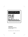
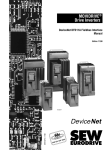
INTERBUS
G4
MOVIDRIVE®
LWL (2MBaud)
I/O (Rugged Line)
03694AXX
Figure 1: Typical design of an INTERBUS fiber optic system
Fieldbus interface DFI21A INTERBUS with fiber optic cable – Manual
5
1
Features of the DFI21 option
1.1
Features of the DFI21 option
Only the transfer medium of the INTERBUS changes for the user through the bus
cabling with fiber optic cables, i.e. bus design, project planning and programming in the
control system are not affected by the use of a fiber optic cable.
The DFI21 option for the MOVIDRIVE® drive inverters is characterized by the following
features:
6
Latest fiber optic technology
Through the use of Supi-3 OPC (Optical Protocol Chip) technology, the light
intensity (output power) of the fiber optic components of the DFI21 is
controlled automatically, so that the fiber optic segment is always operated at
optimum light intensity. At the same time, this procedure allows for permanent
quality monitoring of the optical transmission line.
Integrated detection of bus end
The DFI21 recognizes automatically whether another participant is connected
to the continuing interface.
500 kbps and 2 Mbps
Using a corresponding DIP switch, the DFI21 can be used in 500 kbps and in
2 Mbps INTERBUS systems.
1–6 Process data words
1–4 PCP words
The DFI21 supports a maximum of six input and output words in the
INTERBUS protocol. Classifiying these six words into process and PCP data
is accomplished with the DIP switches. Thus, an application-specific optimum
INTERBUS interface can be implemented between control system and drive
inverter.
Two PCP channels with PCP
version 3
Besides the PCP communications connection with a control system, the
DFI21 also supports a direct PCP connection to the INTERBUS interface
module. This PCP connection can be used for startup, programming and
diagnostics of drive inverters via an additional management PC on the
production control level.
Compatibility with DFI11A
Applications with DFI11A (RS-485 remote bus) can be changed to fiber optics
via DFI21 without changing the project planning and programming of the
control system.
Part number
823 093 5
Fieldbus interface DFI21A INTERBUS with fiber optic cable – Manual
Supported device types
2
Assembly / Installation Instructions
2.1
Supported device types
2
The DFI21A option for INTERBUS connection can be used with all drive inverters in the
MOVIDRIVE® series.
2.2
Installation of option card
Before you begin
•
Discharge your body of electrostatic energy by using appropriate means (anti-static
band, conductive shoes, etc.) before touching the option card.
•
Keep option card in its original packaging and remove it only when you are ready to
install it.
•
Avoid frequent touching of the option card and hold the card only at the edges. Do
not touch any components.
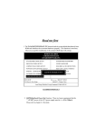
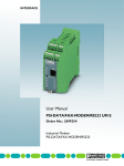
[1]
[2]
[7]
[3]
[4]
[8]
[5]
[6]
03696AXX
Figure 2: DFI 21 option card for INTERBUS fiber optics
[1] DIP switch for process data length, PCP length and baud rate
[2] Diagnostics LEDs
Incoming fiber optic cable remote bus (Remote IN) / [3] Receiver / [4] Sender
Continuing fiber optic cable remote bus (Remote OUT) / [5] Receiver / [6] Sender
[7] Fiber optic cable balance (do not change!)
[8] Supi3 OPC
Fieldbus interface DFI21A INTERBUS with fiber optic cable – Manual
7
2
Installation of option card
Installation of
option card
8
•
Disconnect the supply voltage of the inverter. Switch off the supply voltage and the
24 V supply, if necessary.
•
Remove lower cover of control unit.
•
Unscrew electronics shield terminal.
•
Remove black cover plate.
•
Insert option card into guide rails of OPTION1 slot and push into slot.
•
Apply moderate pressure to the front plate of the option card while pushing it into the
slot.
•
Fasten electronics shield terminal. If the electronics shield terminal cannot be
fastened, the option card was not inserted correctly.
•
Replace cover of control unit.
•
Do not remove the protective cover of the fiber optics output and input until you are
ready to plug in the fiber optics connectors.
•
Depending on the fiber optics connector used, the installation of the cover may not
be possible. This does not affect the enclosure type of the device.
•
The installation of the DFI21A option card is now complete.
•
Fiber optic connections not in use must remain closed using a dust-proof
protective cover.
Fieldbus interface DFI21A INTERBUS with fiber optic cable – Manual
2
INTERBUS topologies with DFI21 option
2.3
INTERBUS topologies with DFI21 option
Using the DFI21 option, the drive inverter is connected to an INTERBUS fiber optics
remote bus. By setting the baud rate, the DFI21 may be operated in 500 kbps and 2
Mbps installations. Although the DFI21 supports the optical control of the transmitter
power, non-controlled fiber optic phases can also be formed if the previous or following
participant does not support optical control.
Installation examples for various bus topologies are listed below.
Direct interface
with 2 Mbps
System
requirements
The implementation of INTERBUS networks with optically controlled fiber optic
technology and a transfer rate of 2 Mbps offers the most efficient networkable solution
with DFI21.
Interface
INTERBUS G4 interface module with optical system diagnostics (e.g.
S7 400 ETH DSC) and optically controlled fiber optics interface or
optical converter (RS485/fiber optics), e.g. IBS OPTOSUB
AK-MA/M/R-LK
CMD tool
version 4.50A or higher
Interbus participants
all INTERBUS components must support 2 Mbps
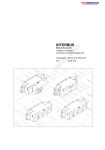
INTERBUS
G4
MOVIDRIVE®
OPTOSUB
SupiOPC
LWL (2MBaud)
03697AXX
Figure 3: 2 Mbps application with optically controlled fiber optics remote bus
All installed components must support the baud rate of 2 Mbps and optical control in
order to obtain an optimal system. It is possible to interface INTERBUS participants with
and without optical control of transmitter power.
Fieldbus interface DFI21A INTERBUS with fiber optic cable – Manual
9
2
INTERBUS topologies with DFI21 option
RS-485/fiber
optics mixed
operation with
500 kbps
System
requirements
The DFI21 may also be used for the installation of sections of fiber optic lines within an
RS485 network.
Interface
all INTERBUS G4 interface modules
CMD tool
version 4.50 or higher
Interbus participants
all types of INTERBUS participants with RS485 or fiber optics
technology (500 kbps)
Optical converters
(Polymer/HC)
for incoming remote bus interface: OPTOSUB-PLUS-K/IN; for
continuing remote bus interface: OPTOSUB-PLUS-K/OUT
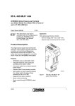
INTERBUS
G4
MOVIDRIVE®
OPTOSUB
plus
OPTOSUB
plus
I/O
RS 485 (Cu)
(500kBaud)
LWL
A
LWL
B
LWL
A
RS 485 (Cu)
03698AXX
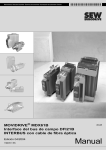
Figure 4: INTERBUS system with fiber optics remote bus segment
A = uncontrolled fiber optics remote bus
B = optically controlled fiber optics remote bus
Figure 4 shows an installation example for mixed operation with RS-485 and fiber optics
bus interface with INTERBUS options DFI11 (RS-485) and DFI21 (fiber optics).
The first drive inverter is coupled with the interface module via an RS-485 bus interface.
The outgoing remote bus interface is converted to fiber optics technology using an
OPTOSUB-PLUS-K/OUT and sent to the fiber optics Remote IN interface of the second
inverter. This segment does not feature an optical control since it is not supported by the
converter.
Data transfer between second and third inverter is accomplished with optically
controlled transmitter power. Interfacing the fourth inverter requires a conversion to
RS-485 technology by using OPTOSUB-PLUS-K/IN. This last fiber optics segment is
once again operated without optical control since it is not supported by OPTOSUBPLUS.
10
Fieldbus interface DFI21A INTERBUS with fiber optic cable – Manual
Bus connection via fiber optics
2
In general, the optical control is independent of the utilized firmware version of the
interface module since it is implemented on the ASIC level between INTERBUS
participants. In order to evaluate the optical system diagnostics, firmware version V4.44
or higher is required for the INTERBUS interface module.
2.4
Bus connection via fiber optics
Bus interfacing for DFI21 is done exclusively via fiber optics. Polymer fiber cables and
HCS cables may be used for this purpose.
Polymer fiber
cable
This type of cable is used for distances up to 70 meters between two interbus
participants. Depending on the operating range, several designs are available. This type
of cable distinguishes itself through simple and cost-effective installation.
HCS cable
This type of cable can be used for distances up to 500 meters since it incurs
considerably lower light attenuation compared to polymer fibers.
The bus cable must be at least 1 meter long. For shorter distances, cable jumpers from
Phoenix Contact must be used.
Note!
Advanced information on proper routing of fiber optic cables can be found in the fiber
optic installation guidelines from Phoenix Contact (item designation IBS SYS FOC
ASSEMBLY).
The appendix contains a checklist for the installation of fiber optic cables.
2.5
Installing fiber optic connectors
F-SMA connectors are used to connect the fiber optic cable to the DFI21 option. Two
connectors each (sender and receiver) are required for the incoming and outgoing
remote bus. In order to maintain optimum bending radius, the use of F-SMA connectors
with kink protection is recommended.
Ordering
information
For F-SMA connectors (e.g. from Phoenix Contact)
Designation
Part designation
F-SMA connector set for polymer fiber cable (4 pieces) with kink protection
PSM-SET-FSMA/4-KT
Fieldbus interface DFI21A INTERBUS with fiber optic cable – Manual
11
2
Installing fiber optic connectors
Connector pin
assignment
For INTERBUS remote bus with fiber optics
Table: Connector pin assignment
Position in
Signal
Direction
Color of fiber optics
cable core
1
Fiber optics remote IN
Input data
orange (og)
2
(incoming remote bus)
Output data
black (bk)
3
Fiber optics remote OUT
Input data
black (bk)
4
(continuing remote bus)
Output data
orange (og)
1
1
og
og
2
bk
2
bk
3
bk
4
og
03699AXX
Figure 5: Fiber optics cable – connector pin assignment DFI21
12
Fieldbus interface DFI21A INTERBUS with fiber optic cable – Manual
Setting of the DIP switches
2.6
2
Setting of the DIP switches
The six DIP switches S1-1 through S1-6 on the front side of the option are used for
setting the process data length and PCP length as well as selecting the baud rate.
[1] Number of process data (1 ... 6 words)
ON
[2] Number of PCP words (1, 2 or 4 words)
2
1
2
2
3
1
5
2
4
4
The figure depicts the following settings:
Process data width: 2 PD
Number of PCP words: 1 PCP
Baud rate: 2 Mbps
6
PACER
[3]
Baud rate: [3] OFF: 2 Mbps / [4] ON: 0.5 Mbps
1
0
2
[2]
ON
[1]
2
2M
0.5M
[4]
DIP switch assignment of DFI21
Note
Before any DIP switches are changed, the drive inverter must be disconnected from
power (supply voltage and 24 V back-up operation). The settings of DIP switches S1-1
through S1-5 are performed only during initialization of the drive inverter.
If incorrect settings of the DIP switches are present, the drive inverter responds with ID
code "Microprocessor not ready" (38 hex).
Setting the baud
rate
DIP switch S1-6 is used to set the baud rate. Changing the baud rate takes effect
immediately and may interrupt the current data communication of the Interbus.
Fieldbus interface DFI21A INTERBUS with fiber optic cable – Manual
13
2
Setting of the DIP switches
Setting the
process data
length and PCP
length
A maximum of six Interbus data words can be exchanged between the INTERBUS
interface module and the DFI21 option. These data words can be distributed to the
process data channel and the PCP channel using DIP switches S1-1 through S1-5. The
limit of six data words results in settings that cannot be mapped onto the Interbus.
In case of an incorrect setting, the DFI21 responds with ID code "Microprocessor not
ready" (38hex) and signals this incorrect setting with the red TR-LED. The following
figure shows the limit conditions for the setting of process data length and PCP length
with the following limits:
[A] PCP setting not in effect!
ON
2
1
2
2
3
1
0
2
1
5
2
4
[A]
ON
6 PD
2
4
6
PACER
2M
0.5M
ID: 03hex (3dez)
Settings for DFI21 operation with six process data
14
Process data length in words
PCP length
ID code
6
PCP setting not in effect;
no PCP channel available
03hex (3dec)
Fieldbus interface DFI21A INTERBUS with fiber optic cable – Manual
2
Display elements
ON
1
2
3
1
2
2
ON
1
5
2
4
4
4 PCP
4
6
PACER
6
PACER
2M
0.5M
ID: E3hex (227dez)
0
1
5
2
2
2
4
2 PCP
6
PACER
2M
2
3
4
max.
2 PD
2
1
1
5
2
2
2
4
1 PCP
0
1
2
3
2
max.
4 PD
2
ON
ON
1
2
2
1
0
ON
max.
5 PD
2
ON
2M
0.5M
ID: E0hex (224dez)
0.5M
ID: E1hex (225dez)
Examples for setting PCP length and maximum process data length
PCP length
Maximum process data length
ID code
1 word
5 words
E3 hex (227dec)
2 words
4 words
E0 hex (224dec)
4 words
2 words
E1 hex (225dec)
If maximum length is exceeded or for
setting 0 or 7 PD
38 hex (56dec) = "Microprocessor not
ready"
All settings not listed here result in the ID code "Microprocessor not ready." The inverter
then signals "PD configuration" = 0PD in parameter P090 and indicates this incorrect
setting by activating the red TR-LED on option DFI21.
2.7
Display elements
The DFI21 option card contains seven LEDs for diagnostics of the INTERBUS system.
These LEDs indicate the current state of the DFI21 and the INTERBUS system
(Figure 6).
UL
CC
BA
RD
FO1
FO2
TR
Logic Voltage (gn = OK)
Cable Check (gr = OK)
Bus Active (gn = ok)
Remote Bus Disabled (rd = off)
Fiber Optic 1 (ye = not OK)
Fiber Optic 2 (ye = not OK)
Transmit (gn = PCP active)
03705AXX
Figure 6: Diagnostics LEDs of DFI21
Fieldbus interface DFI21A INTERBUS with fiber optic cable – Manual
15
2
Display elements
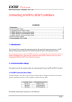
Figure 7 shows frequently occurring LED patterns of the diagnostics LEDs and their
meanings. A detailed description of the LEDs can be found in the following tables.
UL
CC
BA
RD
FO1
FO2
TR
gn
off
off
rd
ye
ye
ye flash, off
UL
CC
BA
RD
FO1
FO2
TR
[A]
gn
off
off
rd
ye
ye
rd
UL
CC
BA
RD
FO1
FO2
TR
[B]
gn
gn
gn blink
rd
ye blink
ye blink
off
UL
CC
BA
RD
FO1
FO2
TR
[C]
gn
gn
gn
off
off
off
off / PCP: gn
[D]
UL
CC
BA
RD
FO1
FO2
TR
gn
gn flash
off
rd
ye
ye
off
[E]
03706AXX
Figure 7: Frequently occurring LED patterns
[A] Power-on of inverter (INTERBUS not yet active)
[B] Incorrect setting of DIP switches (INTERBUS not yet active)
[C] Initialization phase of INTERBUS system
[D] Correct INTERBUS operation
[E] Incorrectly set baud rate
LED UL "U-Logic"
(green)
LED CC "Cable
Check" (green)
LED BA "Bus
Active" (green)
LED RD "Remote
Bus Disable"
(red)
16
Status
Meaning
Fault correction
On
Power supply of bus
electronics is present
-
Off
Power supply of bus
electronics is missing
Verify that the option card is seated correctly and check the
24 V power supply of the inverter.
Status
Meaning
Fault correction
On
Incoming remote bus
connection is functioning
porperly
-
Off
Incoming remote bus
connection is malfunctioning
Check the incoming fiber optic remote bus and the LED
FO1.
Status
Meaning
Fault correction
On
Data transfer on INTERBUS is
active
-
Off
No data transfer; INTERBUS
stopped
Check the incoming remote bus cable. Use the diagnostic
display on the INTERBUS interface module (master) to
localize the fault further.
Status
Meaning
Fault correction
On
Continuing remote bus switched off
-
Off
Continuing remote bus not switched off
-
Fieldbus interface DFI21A INTERBUS with fiber optic cable – Manual
2
Display elements
LED FO1 "Fiber
Optic 1" (yellow)
LED FO2 "Fiber
Optic 2" (yellow)
LED TR
"Transmit"
(green)
Status
Meaning
Fault correction
On
Monitoring of incoming fiber optic line. If the
previous participant
• possesses an optical line diagnostics, the
system reserve of the optical transmission
was undershot
• does not possess an optical line
diagnostics, a control of the optical
transmission power is not possible
Check the incoming fiber optic cable for cable
quality, correct connector installation, bending
radius, etc. Use the optical diagnostics of the
CMD tool or a fiber optic measurement
instrument for further location of faults.
Off
Incoming fiber optic line is functioning
properly
-
Status
Meaning
Fault correction
On
Monitoring of continuing fiber optic line. If the
next participant
• possesses an optical line diagnostics, the
system reserve of the optical transmission
was undershot
• does not possess an optical line
diagnostics, a control of the optical
transmission power is not possible
Check the continuing fiber optic cable for
cable quality, correct connector installation,
bending radius, etc. Use the optical
diagnostics of the CMD tool or a fiber optic
measurement instrument for further location
of faults.
Off
Continuing fiber optic line is functioning
properly
-
Status
Meaning
Fault correction
When the LED TR shows green, it corresponds to the Interbus standard.
LED TR
"Transmit"
(yellow or red)
Off
No PCP communication
-
Green
PCP communication is active or INTERBUS start-up (parameter
access via INTERBUS PCP channel)
-
Status
Meaning
Fault correction
The LED TR indicates system internal conditions with yellow and red that generally do not occur during
INTERBUS operation.
Off or
green
Normal operation (see table for TR = green)
-
Flashing
yellow
Inverter is currently in the initialization phase
-
Constant
red
Selected incorrect DIP switch configuration,
INTERBUS operation is not possible.
Check the settings of the DIP switches S1.
Correct the settings of the DIP switches, if
necessary, and switch the unit on again.
Flashing
red
Incorrect DIP switch configuration or
INTERBUS option card is defect, INTERBUS
operation is not possible.
Check the settings of the DIP switches S1. If
the settings are correct, contact the SEW
Electronics Service.
Fieldbus interface DFI21A INTERBUS with fiber optic cable – Manual
17
3
Startup of the drive inverter
3
Project Planning and Startup
This section describes the project planning and startup of the MOVIDRIVE® drive
inverter with the DFI21A option in the INTERBUS interface module.
3.1
Startup of the drive inverter
After installating the fieldbus option card, the MOVIDRIVE® drive inverter can
immediately be parameterized via the fieldbus system without any additional settings.
For example, after power-on all parameters of the higher-level programmable controller
can be set.
However, in order to control the drive inverter via the INTERBUS system, it must first be
switched over to the control and setpoint source = FIELDBUS. Using the FIELDBUS
setting, the drive inverter is parameterized to the control and setpoint transfer from the
INTERBUS. The drive inverter now responds to the process output data sent by the
higher-level programmable controller.
The activation of the control/setpoint source FIELDBUS is signalled to the higher-level
controller using the "fieldbus mode active" bit in the status word. For safety reasons, the
drive inverter must also be enabled on the terminal side for control via the fieldbus
system. In accordance, the terminals must be connected or programmed so that the
inverter is enabled via the input terminals.
The simplest way of enabling the drive inverter at the terminal side consists of
connecting the input terminal DIØØ (Function/CONTROLLER INHIBIT) with a +24 V
signal and programming the input terminals DIØ1 through DIØ3 to NO FUNCTION .
Figure 8 shows an example of the procedure for the startup of the MOVIDRIVE® drive
inverter with fieldbus interface.
18
Fieldbus interface DFI21A INTERBUS with fiber optic cable – Manual
3
Startup of the drive inverter
Procedure for
startup
1. Enable power output stage on the terminal side.
Connect input terminal DIØØ / X13.1 (Function/CONTROLLER INHIBIT) to a +24 V
signal, e.g. via device jumper.
X13:
DI00
DI01
MOVIDRIVE ®
DI02
DI03
DI04
[A]
DI05
DCOM
V024
DGND
ST11
ST12
X10:
TF1
DGND
DB00
DO01-C
DO01-NO
+
DO01-NC
DO02
−
VO24
24V ext.
VI24
DGND
03692AEN
Figure 8: Wiring for enable
[A] The drive inverter can be enabled on the terminal side with this wire jumper!
X13
DI00: /Controller inhibit
X10
TF1: TF input
DI01 ... X13:DI05: No function
DGND: Reference potential binary
signals
DCOM: Reference DI00 ... DI05
BB00: /Brake
VO24: + 24 V
DO01-C: Relay contact
DGND: Reference potential binary signals
DO01-NO: Relay NO contact
ST11: RS-485 +
DO01-NC: Relay NC contact
ST12: RS-485 -
DO02: /Malfunction
VO24: + 24 V
VI24: + 24 V (external)
2. Switch on 24 V power supply
Only switch on the external 24 V power supply (not the supply voltage!) so that the
drive inverter can be programmed.
Fieldbus interface DFI21A INTERBUS with fiber optic cable – Manual
19
3
Project planning of the INTERBUS system
3. Setpoint source = FIELDBUS / control source = FIELDBUS
To control the drive inverter via fieldbus, program the setpoint source and the control
source to FIELDBUS.
- P100 setpoint source = FIELDBUS
- P101 control source = FIELDBUS
4. Input terminals DIØ1 ... DIØ3 = NO FUNCTION
Programm the functionality of input terminals X13.2, X13.3 and X13.4 to NO
FUNCTION.
- P600 programming terminal DIØ1 (X13.2) = NO FUNCTION
- P601 programming terminal DIØ2 (X13.3) = NO FUNCTION
- P602 programming terminal DIØ3 (X13.4) = NO FUNCTION
Further informationen on startup and control of the MOVIDRIVE® drive inverter can be
found in the manual accompanying the fieldbus communications profile.
3.2
Project planning of the INTERBUS system
There are two steps involved in project planning for the drive inverter in the INTERBUS
interface module using the project planning software "CMD-Tool" (CMD = ConfigurationMonitoring-Diagnosis). The bus structure is created in the first step. Next, the
participants are described and the process data are addressed.
ON
1
1
5
2
4
2 PCP
2
3
2
...
T PAW 144
T PAW 146
T PAW 148
...
2
2
PLC
1
0
ON
3 PD
2
4
6
PACER
2M
0.5M
...
L PEW 144
L PEW 146
L PEW 148
...
PAW 148
PA3
PAW 146
PA2
PAW 144
PA1
PEW 148
PE3
PEW 146
PE2
PEW 144
PE1
INTERBUS
PA1
PA2
PA3
PE1
PE2
PE3
03713AXX
Figure 9: Project planning example for 3PD + 2PCP
The following figures show the settings in the CMD tool for a drive inverter that is
projected with the configuration 3PD + 2PCP in accordance with Figure 9 to the input/
output addresses 144...149 of the controller.
20
Fieldbus interface DFI21A INTERBUS with fiber optic cable – Manual
Project planning of the INTERBUS system
Configuring the
bus structure
The bus structure can be configured online or offline using the CMD-Tool.
Offline
configuration:
Insert with ID code
In offline mode, the drive inverter is projected with the menu item "Edit / Insert with ID
code" in the CMD tool. In accordance with Figure 10, the entries for ID code, process
data channel and device type must be entered.
3
03714AXX
Figure 10: Offline configuration with CMD tool
Note!
Not all combinations are possible since the drive inverter can occupy a maximum of six
words in the INTERBUS.
The following table shows the possible settings. The setting of the ID Code must
correspond to the DIP switches S1-4 and S1-5 on the DFI21 option. The setting of the
process data channel must correspond to the DIP switches S1-1 through S1-3 on the
DFI21 option, otherwise INTERBUS operation is not possible.
Fieldbus interface DFI21A INTERBUS with fiber optic cable – Manual
21
3
Project planning of the INTERBUS system
Information on the
offline configuration of DFI21
option with the
CMD tool
Online
configuration:
Configuration
frame / Read in
22
Program setting
Function (MOVIDRIVE® display)
ID code
227 dec (E3 hex)
Parameter channel: 1 word
Process data
channel:
16 bit
1 process data word (Param+1PD)
32 bit
2 process data words (Param + 2 PD)
48 bit
3 process data words (Param + 3 PD)
64 bit
4 process data words (Param + 4 PD)
80 bit
5 process data words (Param + 5 PD)
ID code
224 dec (E0 hex)
Parameter channel: 2 words
Process data
channel:
16 bit
1 process data word (Param+1PD)
32 bit
2 process data words (Param + 2 PD)
48 bit
3 process data words (Param + 3 PD)
64 bit
4 process data words (Param + 4 PD)
ID code
225 dec (E1 hex)
Parameter channel: 4 words
Process data
channel:
16 bit
1 process data word (Param+1PD)
32 bit
2 process data words (Param + 2 PD)
ID code
3 dec (03 hex)
Parameter channel: -
Process data
channel:
96 bit
6 process data words (6PD)
The INTERBUS system can also be installed completely at first, and the DIP switches
of the DFI21 option can be set. The CMD tool can be used to read in the entire bus
structure (configuration frame). All stations are automatically detected with their data
width settings.
Fieldbus interface DFI21A INTERBUS with fiber optic cable – Manual
Project planning of the INTERBUS system
Creating device
descriptions
3
An individual device description for the drive inverter in the INTERBUS system can be
designed for unique identification and description of the INTERBUS stations.
The following entries are important:
Station description
The fields "Manufacturer Name" and "Device Type" must be furnished with the entries
Manufacturer Name: SEW-EURODRIVE
Device Type: MOVIDRIVE
so that the parameters for the drive can be parameterized with a management PC from
the production control level via the INTERBUS interface module (Figure 11).
Figure 11: Station description for MOVIDRIVE® with DFI21
Interface type
03715AXX
Select "fiber optic remote bus" as interface type.
Fieldbus interface DFI21A INTERBUS with fiber optic cable – Manual
23
3
Project planning of the INTERBUS system
Representation
For simpler identification of the drive inverter, users can copy their own ICO files into the
directory ".\IBSCMD\Pict32\" beginning with CMD tool version 4.50 (Figure 12).
"INTERBUS Description Files for CMD tool" can be found on SEW’s Internet pages at
http://www.SEW-EURODRIVE.de under "Software / Produktunterstützende Software."
03716AXX
Figure 12: Linking the station description with ICO file
24
Fieldbus interface DFI21A INTERBUS with fiber optic cable – Manual
3
Project planning of the INTERBUS system
Parameter channel
The following settings of the parameter channel are necessary, if the PCP channel is to
be used for parameterization of the drive inverter in your application:
•
Message Lengths / Transmit / Receive:
243 bytes each
•
Supported Parameter Channel Services (standard): Read / Write .
03717AXX
Figure 13: Setting of the parameter channel (PCP)
Assigning
process data
INTERBUS process data of the drive inverter are assigned to the program addresses of
the control system using the context menu "Process Data."
03718AXX
Figure 14: Assigning INTERBUS process data and PLC program addresses
A sample program (STEP7) for controlling the drive inverter using the process data of
the INTERBUS can be found in Section 5.
Fieldbus interface DFI21A INTERBUS with fiber optic cable – Manual
25
3
Testing the PCP connection
3.3
Testing the PCP connection
The MONITOR mode of the CMD tools can be used to test the PCP connection to the
drive inverter. The following figures illustrate the procedure for the PCP test. This
procedure establishes a PCP connection to the device and reads the parameter list
(object directory) saved in the device.
Switch the CMD tool to the "Monitoring" mode.
03719AXX
Figure 15: Switching the CMD tool to the "MONITORING" mode
Click on the drive inverter to which you want to establish a PCP connection. Open the
context menu by clicking the right mouse button and select the menu item "Device
Parameterization."
03721AXX
Figure 16: Testing the PCP device parameterization
26
Fieldbus interface DFI21A INTERBUS with fiber optic cable – Manual
3
Testing the PCP connection
Activate the menu item "Device / Read Parameter List" in the "Device Parameterization"
window.
03722AXX
Figure 17: Window for device parameterization via CMD tool
If the device parameters are read in, the project planning of the PCP channel was
performed correctly. The read-in process can be aborted.
If an error message appears instead of the progress indicator, check the PCP
configuration and allocation of CRs. If necessary, reformat the parameterization
memory of the interface module and then write the current project into the
parameterization memory again. Next, perform the parameterization of the interface
module again and repeat this test sequence for checking the PCP connection.
03723AXX
Figure 18: CMD tool reads in device parameters, i.e. PCP communication is ok
Fieldbus interface DFI21A INTERBUS with fiber optic cable – Manual
27
I
4
Basic overview
0
4
The PCP Interface
The MOVIDRIVE® drive inverter provides a standardized interface for parameterization
via the optional DFI21A using the "Peripherals Communication Protocol" (PCP). This
INTERBUS communications channel allows access to all drive parameters of the
MOVIDRIVE® unit.
4.1
Basic overview
The PCP channel must be configured with the corresponding ID code in order to utilize
access to parameter values of the drive inverter. One, two or four words are available in
the INTERBUS protocol for the PCP channel. The access rate to parameter values via
the PCP channel can be varied by the number of PCP words.
Additional PCP
channel for
startup and
diagnostics
The PCP interface for DFI21 is implemented via PCP version 3. Apart from the known
PCP channel between the programmable logic controller (PLC) and drive inverter, an
additional (logical) PCP channel can now be established between interface module and
drive inverter. Using this additional PCP channel, a supervisory computer can access
the parameter values of the drive inverter via the Ethernet/Interbus communications
path.
-CMD Tool
-@X
-MOVITOOLS
Ethernet TCP/IP
PLC
MOVIDRIVE ®
PD
PLC + MOVIDRIVE ®
INTERBUS LWL 2MBd
PCP
PLC
03725AXX
Figure 19: DFI21 communication channels with PCP version 3
Figure 19 shows an example of a systems topology with Ethernet TCP/IP level and
INTERBUS level. An INTERBUS interface module with Ethernet TCP/IP interface that
functions as gateway between the two communication levels is used for this purpose.
28
Fieldbus interface DFI21A INTERBUS with fiber optic cable – Manual
I
The PCP services
4
0
Besides the "CMD-Tool," the higher-level supervisory computer (Windows NT) is also
running the INTERBUS "@utomationXplorer" and "MOVITOOLS" for programming and
parameterization of SEW drive inverters on the INTERBUS. This arrangement allows for
utilizing the existing bus infrastructure for startup and maintenance. This simplifies
startup and diagnostics of the complete automation system since the INTERBUS cable
is now used not only for control purposes but also for startup and diagnostics of all
components used on the fieldbus.
4.2
The PCP services
The MOVIDRIVE® drive inverter with the DFI21A option supports the PCP services
shown in Figure 20. However, only the services for
•
Link establishment ("Initiate")
•
Reading parameter values ("Read")
•
Writing parameter values ("Write")
•
Disconnecting ("Abort")
are important for the parameterization of the inverter. A detailed description of the PCP
services can be found in the user manual for PCP communications of your INTERBUS
interface module.
INTERBUS Slave
INTERBUS Master
Initiate
Abort
Abort/Reject
E
Q
Identify
Get-OV
Status
Read
Write
INTERBUS
Figure 20: PCP services supported by MOVIDRIVE® drive inverter
Fieldbus interface DFI21A INTERBUS with fiber optic cable – Manual
03727AXX
29
4
I
The PCP services
0
Establishing a
communications
link with "Initiate"
The PCP service "Initiate" is used to establish a communications link for
parameterization between an INTERBUS interface module and the MOVIDRIVE® drive
inverter. In principle, the communications link is established from the INTERBUS
interface module. During the link establishment, various settings concerning the
communications link are checked, such as supported PCP services, data blocks, etc.
After successful link establishment, the drive inverter answers with a positive "InitiateResponse." If the link could not be established, the settings concerning the
communications link between INTERBUS interface module and MOVIDRIVE® drive
inverter do not agree. The drive inverter answers with "Initiate-Error-Response." In this
case, compare the list of configured communications relations of the INTERBUS
interface module with that of the drive inverter (see Appendix A).
Any attempt to re-establish an already existing communications link is usually aborted.
Subsequently, no communications link exists so that the PCP service Initiate must be
executed a third time to re-establish the communications link.
30
Disconnecting
the communications link with
"Abort"
The PCP service "Abort" is used to disconnect an existing communications link between
INTERBUS interface module and MOVIDRIVE® drive inverter. Abort is an unconfirmed
PCP service that can be triggered by the INTERBUS interface module and by
MOVIDRIVE®.
Reading
parameter values
with "Read"
The PCP service "Read" is used to grant the INTERBUS interface module read access
to all communications objects (drive parameters) of the MOVIDRIVE® drive inverter.
The documentation MOVIDRIVE® Fieldbus Device Profile and Parameter List contains
a detailed listing of all drive parameters and their coding.
Writing
parameter values
with "Write"
The PCP service "Write" is used to grant the INTERBUS interface module write access
to all MOVIDRIVE® drive parameters. If a drive parameter is accessed incorrectly (e.g.
written value is too high), the drive inverter generates a "Write-Error-Response" with
exact information on the cause of the error.
Fieldbus interface DFI21A INTERBUS with fiber optic cable – Manual
Parameters in the object directory
I
4
0
4.3
Parameters in the object directory
Using the PCP services "Read" and "Write," the INTERBUS interface module can
access all parameters defined in the object directory of the DFI21. All drive parameters
accessible via the bus system are defined as communications objects in the static object
directory of the DFI21. All objects of the static object directory are addressed using
indexes. The following table shows the structure of the object directory of the DFI21 for
the MOVIDRIVE® drive inverter.
The index range is divided into three logical sections. Indexes 8300 … 8800dec are
used to address the drive parameters. The parameter index can be found in the SEW
documentation MOVIDRIVE® Parameter List. Indexes below 8300dec are dealt with
directly on the options card and not to be considered as a drive parameter of the inverter.
Object
description of
drive parameters
Parameter index (decimal)
Designation of communications object
8296
Download parameter block
8297
Last PCP index
8298
Cyclical MOVILINK® parameter channel
8299
Acyclical MOVILINK® parameter channel
8300 ... 8800
Drive parameters for MOVIDRIVE® (directly accessible with PCP services
"Read" and "Write;" for parameter index see SEW documentation
MOVIDRIVE® Parameter List)
8801... 9999
Drive parameters for MOVIDRIVE® (these parameters are accessible only
via MOVILINK® parameter channel)
>10000
Table, program, and variable memory (these parameters are accessible
only via MOVILINK® parameter channel)
A detailed description of the drive parameters of the MOVIDRIVE® drive inverter can be
found in the SEW documentation MOVIDRIVE® Parameter List. Besides the parameter
index, you will find additional information on coding, range of values and meaning of the
parameter data.
The object description in the object list is identical for all drive parameters. Even
parameters that can only be read receive the attribute Read All/Write All in the object list
since the drive inverter performs the corresponding check itself and provides a return
code, if necessary. The following table shows the object description of all drive
parameters.
Index:
8300 ... 8800
Object code:
7 (Simple Variable)
Data type index:
10 (Octet String)
Length:
4
Local address:
Password:
Access groups:
Access rights:
Read all / Write all
Name[16]:
-
Extension length:
-
Fieldbus interface DFI21A INTERBUS with fiber optic cable – Manual
31
4
I
Parameters in the object directory
0
"Download
parameter block"
object
The "Download parameter block" object can be used to write a maximum of 38 drive
parameters of the MOVIDRIVE® at the same time with a single write service.
Consequently, this object offers the possibility to set the parameters of the drive inverter,
for example during the starting phase, with a single call of the write service. Since only
a few parameters will generally have to be changed, this parameter block with a
maximum of 38 parameters is sufficient for nearly all applications. The user data area is
set to 38 x 6 + 2 bytes = 230 bytes (octet string type). The following table shows the
structure of the "download parameter block" object.
Octet
Meaning
Note
0
Reserved (0)
1
Number of parameters
1 ... 38 parameters
2
Index High
1st parameter
3
Index Low
4
MSB data
5
Data
6
Data
7
LSB data
8
Index High
...
...
223
LSB data
224
Index High
225
Index Low
226
MSB data
227
Data
228
Data
229
LSB data
38th parameter
The "download parameter block" object is handled only locally on the fieldbus option
card and defined as listed in the following table.
Index:
8296
Object code:
7 (Simple Variable)
Data type index:
10 (Octet String)
Length:
230
Local address:
Password:
Access groups:
32
Access rights:
Write all
Name[16]:
-
Extension length:
-
Fieldbus interface DFI21A INTERBUS with fiber optic cable – Manual
Parameters in the object directory
I
4
0
The WRITE service to the "download parameter block" object on the fieldbus option card
starts a parameterization mechanism that writes sequentially all parameters listed in the
user data area of the object into the DPRAM and, thereby, sets the parameters of the
drive inverter. After successful processing of the download parameter block, i.e. all
parameters transferred by the INTERBUS interface module were written, the write
service concludes with a positive write response. In case of an error, a negative write
response is returned. Consequently, the return code contains more exact information on
the type of error and the number of the parameter (no.1 ... 38) where the error occurred
(see example).
Example: Error writing the 11th parameter write-error-response:
Error class: 8 Other
Error code: 0
Other
Additional code High: 11dec Error writing parameter 11
Additional code Low: 15hex Value too high
Observe the following note while using the download parameter block:
"Last PCP index"
object
•
Do not execute any factory setting within the download parameter block!
•
After activating the parameter lock, all subsequently written parameters are rejected.
This object is 4 bytes long and returns the numerical value for the last directly accessible
index via the PCP services if a read access occurs. PCP accesses to indexes that are
larger than this numerical value must be performed via the "acyclical MOVILINK®
parameter channel" object.
Index:
8297
Object code:
7 (Simple Variable)
Data type index:
10 (Octet String)
Length:
4
Local address:
Password:
Access groups:
"Cyclical
MOVILINK®
parameter
channel" object
Access rights:
Read all
Name[16]:
-
Extension length:
-
This object is 8 bytes long and contains the cyclical MOVILINK® parameter channel. All
MOVILINK® communications services can be performed with the cyclically alternating
reading and wiriting of this object. The communications service is performed only with
the change of the handshake bit within the management byte. The MOVILINK®
parameter channel allows for access to all indexes and, therefore, also to the IPOS
variable and program memory.
Fieldbus interface DFI21A INTERBUS with fiber optic cable – Manual
33
4
I
Parameters in the object directory
0
The following table shows the structure of this communications object. The structure of
the paramer channel can be found in the documentation "MOVIDRIVE® Fieldbus Device
Profile and Parameter List."
Octet
0
1
2
3
4
5
6
7
Meaning
Mngmt
Res’d
Index
High
Index
Low
MSB
data
Data
Data
LSB data
Note
Mngmt
Res’d
Parameter index
4-byte data
The "cyclical MOVILINK® parameter channel" object is handled only locally on the
fieldbus option card.
Index:
8298
Object code:
7 (Simple Variable)
Data type index:
10 (Octet String)
Length:
8
Local address:
Password:
Access groups:
Access rights:
Read all/Write all
Name[16]:
-
Extension length:
-
The following table shows the process of a parameter access via the cyclical
MOVILINK® parameter channel. The service execution is started in the inverter only
after the control in the parameter channel has changed the handshake bit. For this
purpose, the controller must read the parameter channel at the beginning of the
parameterization in order to obtain the current state of the handshake bit in the inverter.
With the change of the handshake bit, the master can now implement the evaluation of
the parameter channel in the inverter.
34
Fieldbus interface DFI21A INTERBUS with fiber optic cable – Manual
I
Parameters in the object directory
4
0
The inverter now executes the service coded in the parameter channel und re-enters the
service confirmation in the parameter channel. With the controller’s next read access to
the "cyclical MOVILINK® parameter channel," the channel receives the service
confirmation. The following table shows the process of the cyclically called read/write
services for the "cyclical MOVILINK® parameter channel."
MOVIDRIVE® (slave)
Control (master)
1. "READ cyclical MOVILINK® parameter channel" to evaluate the state of the handshake bit.
READ 8298 (parameter channel)
Data = parameter channel
2. Implement the execution of the service coded in the parameter channel with WRITE on the "cyclical
MOVILINK® parameter channel" and toggle of the handshake bit.
WRITE 8298 (parameter channel)
OK
3. READ "cyclical MOVILINK® parameter channel" and evaluation of service confirmation in the parameter
channel.
READ 8298 (parameter channel)
Data = parameter channel with result
"Acyclical
MOVILINK®
parameter
channel" object
The "acyclical MOVILINK® parameter channel" object is 8 bytes long and contains the
MOVILINK® parameter channel. This object can be used for acyclical parameter
access, i.e., the drive inverter executes the processing of the service coded in the
parameter channel every time it receives a WRITE service to this object. The handshake
bit is not evaluated! The following table shows the structure of the "acyclical MOVILINK®
parameter channel." The structure of the parameter channel can be found in the
documentation "MOVIDRIVE® Fieldbus Device Profile and Parameter List."
Octet
0
1
2
3
4
5
6
7
Meaning
Mngmt
Res’d
Index
High
Index
Low
MSB
data
Data
Data
LSB data
Note
Mngmt
Res’d
Parameter index
4-byte data
In principle, two processes are distinguished for parameterization of the drive inverter
via acyclical MOVILINK® parameter channel:
•
Parameter channel performs a write service
•
Parameter channel performs a read service
Fieldbus interface DFI21A INTERBUS with fiber optic cable – Manual
35
4
I
Parameters in the object directory
0
Parameter channel
performs a write
service
If a write service is executed via the acyclical parameter channel (e.g., Write Parameter
or Write Parameter Volatile), the inverter responds with the current service confirmation
after the service has been executed. An incorrect write access returns the
corresponding error code.
This option offers the advantage that the write service can be processed upon sending
a single WRITE "MOVILINK® parameter channel" and the service confirmation can be
accomplished by evaluating the "Write-Confirmation." The following table shows the
execution of write services via the acyclical MOVILINK® parameter channel.
MOVIDRIVE® (slave)
Control (master)
1. Implement the execution of the service coded in the parameter channel with WRITE on the "cyclical
MOVILINK® parameter channel" object.
WRITE 8298 (parameter channel)
Service confirmation (OK/Error code)
The WRITE service coded in the parameter channel is executed and the service
confirmation is returned directly as answer.
Parameter channel
performs a read
service
To read a parameter via the parameter channel, it is necessary to execute a PCP
WRITE service first. The PCP WRITE service determines the standby location for the
data of the inverter. A read service must be executed on the acyclical parameter channel
so that these data can reach the master. Therefore, the execution of read services via
the parameter channel always requires a PCP WRITE and then a PCP READ. The
following table shows the execution of read services via the acyclical MOVILINK®
parameter channel.
MOVIDRIVE® (slave)
Control (master)
1. Implement the execution of the service coded in the parameter channel with WRITE on the "cyclical
MOVILINK® parameter channel" object.
WRITE 8298 (parameter channel)
OK
2. READ "cyclical MOVILINK® parameter channel" and evaluation of service confirmation in the parameter
channel.
READ 8298 (parameter channel)
Data = parameter channel with result
1. Receipt is confirmed immediately; parameter channel is evaluated and requested
service is executed.
2. Service confirmation is entered into parameter channel and can be evaluated via
READ access in the master.
36
Fieldbus interface DFI21A INTERBUS with fiber optic cable – Manual
Parameterization return codes
I
4
0
The acyclical MOVILINK® parameter channel is handled locally only on the fieldbus
option card and defined as listed in the following table.
Index:
8299
Object code:
7 (Simple Variable)
Data type index:
10 (Octet String)
Length:
8
Local address:
Password:
Access groups:
4.4
Access rights:
Read all/Write all
Name[16]:
-
Extension length:
-
Parameterization return codes
In case of incorrect parameterization, the drive inverter returns various return codes to
the parameter setting master that provide detailed information on the cause of the error.
In general, the structural design of these return codes corresponds to EN 50170. The
following components are being distinguished:
•
Error class
•
Error code
•
Additional code
These return codes apply to communications interfaces of the MOVIDRIVE®.
Error class
The error class component provides a more exact classification of the error type. The
error classes listed in Table 1 are distinghuised in accordance with EN 50710.
Class (hex)
Designation
Meaning
1
vfd state
Status error of the virtual field device
2
application reference
Error in application program
3
definition
Definition error
4
resource
Resource error
5
service
Error at service execution
6
access
Access error
7
ov
Error in object list
8
other
Other error (see Additional Code)
Except for error class 8 = other error, the error class is generated by the communications
software of the fieldbus card in case of a faulty communication. Return codes that are
provided by the drive inverter system fall under the category error class 8 = other error.
The more detailed error breakdown is achieved with the additional code component.
Fieldbus interface DFI21A INTERBUS with fiber optic cable – Manual
37
I
4
Parameterization return codes
0
38
Error code
The error code component allows for a more detailed breakdown of the error cause
within the error class and is generated by the communications software of the fieldbus
card in case of faulty communication. For error class 8 = other error, only error code =
0 (other error code) is defined. In this case, the detailed breakdown is achieved in the
additional code.
Additional code
The additional code contains SEW-specific return codes for faulty parameterization of
the drive inverter. They are returned to the master under error class 8 = other error.
Table 2 shows all possible codings for the additional code.
Add.-Code
high (hex)
Add.-Code low
(hex)
Meaning
00
00
No error
00
10
Illegal parameter index
00
11
Function/parameter not implemented
00
12
Read access only
00
13
Parameter lock is active
00
14
Factory setting is active
00
15
Value too large for parameter
00
16
Value too small for parameter
00
17
Required option card missing for this function/parameter
00
18
Error in system software
00
19
Parameter access only via RS485 process interface to X13
00
1A
Parameter access only via RS485 diagnostics interface
00
1B
Parameter is access-protected
00
1C
Controller inhibit required
00
1D
Illegal value for parameter
00
1E
Factory setting was activated
00
1F
Parameter was not saved in EEPROM
00
20
Parameter cannot be changed with released output stage
Fieldbus interface DFI21A INTERBUS with fiber optic cable – Manual
Parameterization return codes
I
4
0
Special case
"Internal
communications
error"
Error correction
The return code listed in the following table is returned if a communications error occurs
between option card and inverter system. The PCP service transmitted via the fieldbus
may not have been executed and should be repeated. If this error occurs again, the drive
inverter must be completely switched off and back on again to perform a new
initialization.
Code (dec)
Meaning
Error class:
6
Access
Error code:
2
Hardware fault
Add. code high:
0
-
Add. code low:
0
-
Repeat the read or write service. If the error occurs again, the drive inverter should be
completely switched off and back on again. If this error occurs permanently, consult the
SEW electronics service.
Fieldbus interface DFI21A INTERBUS with fiber optic cable – Manual
39
5
Control via process data
5
Application Examples
This section features small application examples for process data exchange and
parameterization of the drive inverter via PCP interface.
5.1
Control via process data
The control of the drive inverter via process data is accomplished through simple
reading/writing of program addresses to which the INTERBUS process data of the drive
inverter are mapped. For example, a simple STEP7 program for Simatic S7 looks as
follows:
L W#16#0006
T PAW 144
//writing 6hex to PA1 (control word = enable)
L 1500
T PAW 146
//writing 1500dec to PA2 (speed setpoint value = 300 1/min)
L W#16#0000
T PAW 148 //writing 0hex to PA3 (no function based on factory setting)
Advanced information on the inverter control via process data channel, especially on the
coding of the control and status word, can be found in the manual of the fieldbus device
profile.
5.2
Parameterization via PCP Interface
This section describes how parameters and IPOS variables can be read or written via
the standardized INTERBUS PCP services "Read" and "Write." The example applies to
all INTERBUS interface modules of generation 4 (G4) and is explained in the PHOENIX
nomenclature.
The coding examples shown in the following sections are presented in the same way as
they are described in the INTERBUS user manual "Peripherals Communication Protocol
(PCP)" by Phoenix Contact.
Requirement
40
The following user manuals should be available:
•
INTERBUS user manual "Peripherals Communication Protocol (PCP)," PHOENIX
CONTACT, IBS SYS PCP G4 UM
•
MOVIDRIVE® manual for Fieldbus Device Profile (publication no. 0919 1615)
•
MOVIDRIVE® manual INTERBUS DFI Fieldbus Interface (publ. no. 0919 1410)
Fieldbus interface DFI21A INTERBUS with fiber optic cable – Manual
5
Representation of coding examples
5.3
Representation of coding examples
The coding examples shown in the following sections are presented in the same way as
they are described in the INTERBUS user manual "Peripherals Communication Protocol
(PCP)" by Phoenix Contact.
All information of a PCP service is represented word by word in stacked form, i.e. a word
can be regarded as an SPS word (e.g. Simatic data word). In each case, the right side
shows a coding example for the MOVIDRIVE® drive inverter. All codings shown in red
bold typface are interface or project-specific. All other codings do not change for access
to different drives or drive parameters.
The "Communication Reference (CR)" is used to select the drive inverter whose
parameters are to be set. In the following examples, the drive inverter was assigned CR
= 02 hex in the CMD tool. The index defines the drive parameter that is to be accessed.
Subscriber
description of the
inverter in the
CMD tool
5.4
Word
Meaning
Coding (hex)
1
Command_Code
00 81
2
Parameter_Count
00 03
Before the PCP channel of the drive inverter can be used, the subscriber description in
the CMD tool must be projected for the inverter.
Procedure of a parameterization sequence
The Peripherals Communication Protocol (PCP) of the INTERBUS standardizes access
to parameter data by INTERBUS subscribers and requires the following procedure:
•
Initializing the PCP connection with the "Initiate" service.
•
Reading or writing parameters with the "Read" and "Write" services.
•
If the communications link is no longer required, it can be terminated with the "Abort"
service (the service is not discussed here since it is frequently not required; see PCP
manual).
•
Initializing the PCP connection with the "Initiate" service.
Access to the drive parameters of the inverters takes place only after the PCP
connection has been established with "Initiate_Request." This can be done, for
example, in a single equipment startup.
Word
Meaning
Coding (hex)
1
Command_Code = Initiate_Request
00 8B
2
Parameter_Count
00 02
3
-
Comm._Reference
00 02
4
Password
Access_Groups
00 00
Bits
15 ... 8
7 ... 0
After sending this service, the positive message "Initiate_Confirmation" should be
received (for negative message, see the PCP manual).
Fieldbus interface DFI21A INTERBUS with fiber optic cable – Manual
41
5
Reading a drive parameter
5.5
Reading a drive parameter
Reading a drive parameter (with index £ 8800) is done with the "Read" service. The
drive parameters are generally 4 bytes (1 double word) long.
Example
Reading P130 ramp t11 on RIGHT (index 8470dec = 2116hex)
Word
Meaning
Coding (hex)
1
Command_Code = Read_Request
00 81
2
Parameter_Count
00 03
3
Invoke_ID
Comm._Reference
4
00 02
Index
21 16
5
Subindex
-
Bits
15 ... 8
7 ... 0
00 00
After sending this service, the positive "Read_Confirmation" message should be
received.
Word
Meaning
Coding (hex)
1
Message_Code = Read_Confirmation (+)
80 81
2
Parameter_Count
00 05
3
Invoke_ID
Comm._Reference
4
00 02
Result (+)
00 00
5
-
Length
00 04
6
Data [1]
Data [2]
00 00
7
Data [3]
Data [4]
07 D0
Bits
15 ... 8
7 ... 0
The parameter data are displayed in Motorola format (Simatic format) as follows:
Data [1] = High Byte
Data [2] = Low Byte
Data [3] = High Byte
Data [4] = Low Byte
00 hex
00 hex
07 hex
D0 hex
00 00 07 D0 hex = 2000 dec (= 2000 ms ramp)
Additional information on the coding of drive parameters can be found in the parameter
list in the appendix of the "Fieldbus Device Profile" manual.
Word
Meaning
Coding (hex)
1
Message_Code = Read_Confirmation
80 81
2
Parameter_Count
00 03
3
Invoke_ID
Comm._Reference
00 02
4
Error_Class
Error_Code
08 00
5
Bits
Additional_Code
15 ... 8
00 10
7 ... 0
The table shows an example of the return code "Value too large for parameter."
42
Fieldbus interface DFI21A INTERBUS with fiber optic cable – Manual
5
Writing a drive parameter
5.6
Writing a drive parameter
Writing a drive parameter (with index £ 8800) is done with the "Write" service. The drive
parameters are generally 4 bytes (1 double word) long.
Example
Writing the ramp time 1.65 s on P130 "Ramp t11 on RIGHT"
Index: 8470dec = 2116hex
Value: 1.65s = 1650ms = 1650 dec = 0000 0672 hex
The parameter data are displayed in Motorola format (Simatic format) as follows:
Data [1] = High Byte
Data [2] = Low Byte
Data [3] = High Byte
Data [4] = Low Byte
00 hex
00 hex
06 hex
72 hex
Additional information on the coding of drive parameters can be found in the parameter
list in the appendix of the "Fieldbus Device Profile" manual.
Word
Meaning
Coding (hex)
1
Command_Code = Write_Request
00 82
2
Parameter_Count
00 05
3
Invoke_ID
Comm._Reference
4
Index
00 02
21 16
5
Subindex
Length
00 04
6
Data [1]
Data [2]
00 00
7
Data [3]
Data [4]
06 72
Bits
15 ... 8
7 ... 0
Word
Meaning
Coding (hex)
1
Message_Code = Write_Confirmation (+)
80 82
2
Parameter_Count
00 02
3
Invoke_ID
4
Bits
Comm._Reference
Result (+)
00 02
00 00
15 ... 8
7 ... 0
After sending this service, the positive "Write_Confirmation" message should be
received.
Word
Meaning
Coding (hex)
1
Message_Code = Write_Confirmation (-)
80 82
2
Parameter_Count
00 03
3
Invoke_ID
Comm._Reference
00 02
4
Error_Class
Error_Code
08 00
5
Bits
Additional_Code
15 ... 8
00 15
7 ... 0
The table shows an example of the return code "Value too large for parameter."
Fieldbus interface DFI21A INTERBUS with fiber optic cable – Manual
43
5
Writing IPOS variables / parameters via MOVILINK® parameter
5.7
Writing IPOS variables / parameters via MOVILINK® parameter
The drive inverters provide a special parameter access via MOVILINK® parameter
channel for universal write access to all data of the drive inverter (parameters, IPOS
variables, IPOS program code, etc.). The following mechanism shows how IPOS
variables can be changed via the parameter channel.
The acyclical parameter channel can be utilized via index 8299 dec (206B hex).
Example
Writing the value 74565 of IPOS variable H0 = Index 11000 dec (2AF8 hex)
Value to be written = 74565 dec (0001 2345 hex)
Word
Meaning
Coding (hex)
1
Command_Code = Write_Request
00 82
2
Parameter_Count
00 07
3
4
Invoke_ID
Comm._Reference
Index = MOVILINK parameter channel
00 02
20 6B
5
Subindex
Length
00 08
6
Data [1] = Management byte
Data [2] = Reserved
32 00
7
Data [3/4] = Index (e.g., IPOS variable)
2A F8
8
Data [5]
Data [6]
00 01
9
Data [7]
Data [8]
23 45
Bits
15 ... 8
7 ... 0
After sending this service, the "Write_Confirmation" is issued. The return codes can be
used again to evaluate the negative message.
5.8
Reading IPOS variables / parameters via MOVILINK® parameter
The drive inverters provide a special parameter access via MOVILINK® parameter
channel for universal read access to all data of the drive inverter (parameters, IPOS
variables, IPOS program code, etc.). The following mechanism shows how IPOS
variables can be read via the parameter channel. This requires a two-step procedure:
•
Writing the MOVILINK® parameter channel with the command "Read IPOS Variable
H0"
•
Reading the MOVILINK® parameter channel
The MOVILINK® parameter channel (acyclical) can be utilized via index 8299 dec (206B
hex).
44
Fieldbus interface DFI21A INTERBUS with fiber optic cable – Manual
5
Reading IPOS variables / parameters via MOVILINK® parameter
Example
Reading the IPOS variable H0 = Index 11000 dec (2AF8 hex)
A detailed explanation of the MOVILINK® parameter channel can be found in the
"MOVIDRIVE® Fieldbus Device Profile" manual; also observe the notes in the
"MOVIDRIVE® Fieldbus Interface INTERBUS DFI11A" manual.
Word
Meaning
Coding (hex)
1
Command_Code = Write_Request
00 82
2
Parameter_Count
00 07
3
4
Invoke_ID
Comm._Reference
Index = MOVILINK parameter channel
00 02
20 6B
5
Subindex
Length
00 08
6
Data [1] = Management byte
Data [2] = Reserved
31 00
7
Data [3/4] = Index (e.g., IPOS variable)
2A F8
8
Data [5]
Data [6]
00 00
9
Data [7]
Data [8]
00 00
Bits
15 ... 8
7 ... 0
After receiving the positive "Write_Confirmation (+)," a read access to the MOVILINK®
parameter channel is performed with which the read data are read into the interface
module. These data were previously defined with a read request via "Write_Request."
Word
Meaning
Coding (hex)
1
Command_Code = Read_Request
00 81
2
Parameter_Count
00 03
3
4
Invoke_ID
Comm._Reference
Index = MOVILINK parameter channel
5
Subindex
-
Bits
15 ... 8
7 ... 0
00 02
20 6B
00 00
After sending this service, the positive "Read_Confirmation" message should be
received.
Word
Meaning
Coding (hex)
1
Message_Code = Read_Confirmation (+)
80 81
2
Parameter_Count
00 07
3
Invoke_ID
4
Comm._Reference
Result (+)
00 02
00 00
5
-
Length
00 08
6
Data [1] = Management byte
Data [2] = Reserved
31 00
7
Data [3/4] = Index (e.g., IPOS variable)
2A F8
8
Data [5]
Data [6]
00 01
9
Data [7]
Data [8]
23 45
Bits
15 ... 8
7 ... 0
Fieldbus interface DFI21A INTERBUS with fiber optic cable – Manual
45
5
Writing several IPOS variables / parameters via download parameter
Word
Meaning
Coding (hex)
1
Message_Code = Read_Confirmation
80 81
2
Parameter_Count
00 03
3
Invoke_ID
Comm._Reference
00 02
4
Error_Class
Error_Code
08 00
5
Additional_Code
Bits
15 ... 8
00 10
7 ... 0
The return codes can be used to evaluate the negative message.
5.9
Writing several IPOS variables / parameters via download parameter
The MOVIDRIVE® drive inverters make it possible to write several IPOS variables or
parameters simultaneously with a single PCP service using the download parameter
block.
The download parameter block is always 230 bytes long. A maximum of 42 drive
parameters or IPOS variables can written in one block.
Example
46
Three values of the inverter are to be written with one "Write_Request."
Name of parameter/variable
Index
Value to be written
IPOS variable H0
11000 dec (2AF8 hex)
1 dec (1 hex)
IPOS variable H1
11001 dec (2AF9 hex)
-40000 dec (FFFF63C0 hex)
P130 ramp t11 on RIGHT
8470 dec (2116 hex)
1500 dec (05DC hex)
Fieldbus interface DFI21A INTERBUS with fiber optic cable – Manual
5
Writing several IPOS variables / parameters via download parameter
After sending this service, the "Write_Confirmation" is issued. The return codes can be
used again to evaluate the negative message. Since the individual parameters of the
download parameter block are written sequentially in the inverter, a negative
"Write_Confirmation" will cause the parameter number where the error occurred to be
entered into the High section of the Additional_Codes.
Word
Meaning
Coding (hex)
1
Command_Code = Write_Request
00 82
2
Paraemter_Count = 118 words (= 76 hex)
00 76
3
4
Invoke_ID
Comm._Reference
Index = Download parameter block
00 02
20 68
5
Subindex
Length = 230 bytes (= E6 hex)
00 E6
6
Data [1] = Reserved
Data [2] = Number of
parameters
00 03
7
Data [3/4] = Index of first parameter (e.g., IPOS variable H0)
2A F8
8
Data [5]
Data [6]
00 00
9
Data [7]
Data [8]
00 01
10
Data [9/10] = Index of first parameter (e.g., IPOS variable H1)
2A F9
11
Data [11]
Data [12]
FF FF
12
Data [13]
Data [14]
63 C0
13
Data [15/16] = Index of first parameter (P130 ramp t11)
21 16
14
Data [17]
Data [18]
00 00
15
Data [19]
Data [20]
05 DC
...
...
...
...
Bits
15 ... 8
7 ... 0
After sending this service, the "Write_Confirmation" is issued. The return codes can be
used again to evaluate the negative message. Since the individual parameters of the
download parameter block are written sequentially in the inverter, a negative
"Write_Confirmation" will cause the parameter number where the error occurred to be
entered into the High section of the Additional_Codes (see also DFI manual).
Fieldbus interface DFI21A INTERBUS with fiber optic cable – Manual
47
kVA
6
i
f
n
Compatibility with DFI11 (RS485 Cu)
P Hz
6
Appendix
6.1
Compatibility with DFI11 (RS485 Cu)
For INTERBUS applications using RS-485 (Cu) transfer technology that were
implemented with the MOVIDRIVE® DFI11 option, the transfer medium can be changed
over to the drive inverter at any time by replacing the DFI11 option with the DFI21 option
(fiber optic connection technology). The following tables show the compatibility between
DFI11 and DFI21. In principle, all DFI11 applications can be replaced by DFI21. The
peripheral conditions listed in the tables must be followed, if a fiber optic application with
the DFI21 is to be replaced by an RS485 interface with DFI11.
INTERBUS
configuration
Parameter
channel (PCP
interface)
Supported configurations
DFI11(RS485 Cu)
DFI21(fiber optic link)
ID code: 227 decimal (E3hex)
yes
yes
1 PD + 1 PCP
yes
yes
2 PD + 1 PCP
yes
yes
3 PD + 1 PCP
yes
yes
ID code: 224 decimal (E0hex)
-
yes
1...4 PD + 2 PCP
-
yes
ID code: 225 decimal (E1hex)
-
yes
1 / 2 PD + 4 PCP
-
yes
ID code: 3 decimal (03hex)
-
yes
6 PD
-
yes
Supported features
DFI11(RS485 Cu)
DFI21(fiber optic link)
Send message length:
243 bytes
243 bytes
Receive message length:
243 bytes
243 bytes
Read
yes
yes
Write
yes
yes
8296 download parameter block
yes
yes
8297 last PCP index
-*
yes
yes
yes
8299 acyclical MOVILINK®
parameter channel
yes
yes
8300 ... 8800 drive parameter
yes
yes
Parameter channel settings:
Supported services:
Elements of the object list:
8298 cyclical MOVILINK
parameter channel
48
®
Fieldbus interface DFI21A INTERBUS with fiber optic cable – Manual
kVA
Check list for installation of fiber optic cables
i
f
n
6
P Hz
Supported features
DFI11(RS485 Cu)
DFI21(fiber optic link)
8801 ... 9999 drive parameter
yes
yes
>10000 tables, program, variables
yes
yes
PCP services of the controller:
0
0..7Fhex for control system
PCP services via interface module:
not possible
80..FFhex for interface module
PCP version
1.50**
3.x
Second logical PCP channel for
interface module:
no
yes
Coding of Invoke ID:
* Last PCP index
The object "Last PCP index" is not implemented and returns an error message when a
read access occurs.
** Different PCP versions
Although the PCP versions are distinguished between DFI11 and DFI21, the PCP
interface with the interface module or PLC is identical for both modules. With the
exception of the advanced functions of the DFI21 (2 or 4 PCP words, second logical
PCP channel, etc.), INTERBUS applications that utilize the PCP channel of the DFI11
can also be used with the DFI21.
6.2
Check list for installation of fiber optic cables
Routing fiber
optic cables
Protective
measures for
fiber optic cables
Pre-fabricating
fiber optic cables
Calibrating fiber
optic cables
•
Do not exceed maximum cable length
•
Adhere to bending radius
•
Do not crimp or kink fiber optic cables
•
Do not exceed tensile load during cable installation
•
Unroll fiber optic cables only with an unrolling device during installation
•
Protect/secure against tensile load and inadmissible small bending radii
•
Loop-free routing
•
Protect against sharp edges
•
Install separate from power cables
•
Use special cable for routing in special areas (e.g., underground cable or close to
welding robots)
•
Strip outer sheath and single core without damaging them
•
Secure single core in the connector (strain relief)
•
Polish and assemble connector face according to regulations
•
Check the light intensity with respect to limit values (optical diagnostics with CMD
tool or fiber optic measuring instrument)
Fieldbus interface DFI21A INTERBUS with fiber optic cable – Manual
49
7
Index
A
Abort 29, 30
Acyclical MOVILINK® parameter channel 35
Additional code 38
Application example 40
Assembly 7
Assigning process data 25
B
BA 16
Baud rate 13
Bus Active 16
Bus interface 11
C
Cable Check 16
Cable types 11
CC 16
CMD tool 20
Coding example 41
Communications error 39
Compatibility 6, 48
Configuration Monitoring Diagnosis 20
Configuration of bus structure 21
Configuration offline 21
Configuration online 22
Configuring the bus structure 21
Connector for fiber optic connection 11
Connector pin assignment 12
Cyclical MOVILINK® parameter channel 33
D
Detection of bus end 6
Device parameterization 26, 27
Device type 23
DIP switch 13
Disconnecting 29, 30
Disconnecting the communications link 30
Display elements 15
Download parameter block 32, 46
Drive parameters 31
E
Error class 37
Error code 38
Establishing a link 30
Establishing the communications link 30
Example 40
F
Features 6
Fiber Optic 1 17
Fiber Optic 2 17
Fiber optic connector 11
50
FO1 17
FO2 17
H
HCS cable 11
I
ID code 22
Ident code 21
Initiate 29, 30
Installation 7
Installation of fiber optic cables 49
Installation of option card 8
Installing fiber optic cables 49
Installing the option card 8
Interface type 23
Internal communications error 39
L
Last PCP index 33
LED BA 16
LED CC 16
LED FO1 17
LED FO2 17
LED RD 16
LED TR 17
LED UL 16
LEDs 15
Link establishment 29
M
Manufacturer name 23
Message length 25
Monitoring 26
MOVILINK® parameter channel 44
N
Number of PCP words 13
Number of process data 13
O
Object description 31
Object directory 31
Offline configuration 21
Online configuration 22
P
Parameter channel 25
Parameterization sequence 41
Parameterization, return codes 37
Parameters in the object directory 31
PCP connection 26
PCP interface 28
PCP length 13, 14
PCP services 29
Fieldbus interface DFI21A INTERBUS with fiber optic cable – Manual
Performance characteristics 6
Polymer fiber cable 11
Process data channel 21, 22
Process data length 13, 14
Process data manager 25
Program setting 22
Project Planning 18, 20
R
RD 16
Read 29, 30, 36, 42, 44
Read parameter list 27
Reading drive parameters 42
Reading in the bus structure 22
Reading in the configuration frame 22
Reading IPOS variables 44
Reading parameter list 27
Reading parameter values 29, 30
Reading parameters 44
Remote Bus Disable 16
Return codes 37
S
SEW icons 24
Startup 18, 19
Station description 23
Supported parameter channel services 25
T
Topologies 9
direct interface 9
Mixed operation 10
TR 17
Transmit 17
Type of station 21
U
UL 16
U-Logic 16
Unit design 7
W
Write 29, 30, 36, 43, 44, 46
Writing drive parameters 43
Writing IPOS variables 44, 46
Writing parameter values 29, 30
Writing parameters 44, 46
Fieldbus interface DFI21A INTERBUS with fiber optic cable – Manual
51
SEW-EURODRIVE GmbH & Co · P.O.Box 30 23 · D-76642 Bruchsal/Germany · Phone +49- 72 51-75-0
Fax +49-72 51-75-19 70 · http://www.SEW-EURODRIVE.com · sew @ sew-eurodrive.com
SEW-EURODRIVE around the world
Argentina
1619 Garin
Tel. (0 33 27) 45 72 84
Fax (0 33 27) 45 72 21
Australia
Tel. (03) 99 33 10 00
Tullamarine, Victoria 3043 Fax (03) 99 33 10 03
(Melbourne)
Austria
A-1230 Wien
Tel. (01) 6 17 55 00-0
Fax (01) 6 17 55 00-30
Belgium
B-1300 Wavre
Tel. (0 10) 23 13 11
Fax (0 10) 23 13 36
Brazil
07210 Guarulhos-SP
Tel. (0 11 ) 64 60-64 33
Fax (0 11 ) 64 80-43 43
Canada
Bramalea,
Ontario L6T 3W1
Tel. (9 05) 7 91-15 53
Fax (9 05) 7 91-29 99
Chile
Tel. (02) 6 23 82 03
RCH-Santiago de Chile
6 23 81 63
Fax (02) 6 23 81 79
China
Tianjin 300457
Tel. (0 22) 25 32 26 12
Fax (0 22) 25 32 26 11
Colombia
Bogota
Tel. (05 71) 5 47 50 50
Fax (05 71) 5 47 50 44
Denmark
DK-2670 Greve
Tel. 4395 8500
Fax 4395 8509
Finland
FIN-15860 Hollola 2
Tel. (3) 58 93 00
Fax (3) 7 80 62 11
France
F-67506 Haguenau
Tel. 03 88 73 67 00
Fax 03 88 73 66 00
Great Britain
Tel. 19 24 89 38 55
Normanton,
Fax 19 24 89 37 02
West-Yorkshire WF61QR
Hong Kong
Kowloon, Hong Kong
Tel. 2-7 96-04 77
Fax 2-7 95-91 29
India
Baroda
Tel. (02 65) 83 10 86
Fax (02 65) 83 10 87
Italy
Tel. 02-96 98 01
I-20020 Solaro (Milano) Fax 02-96 79 97 81
Japan
438 Shizuoka-ken,
Iwata-gun, Toyoda-cho
Tel. (0 53 83) 7 38 11-13
Fax (0 53 83) 7 38 14
Malaysia
81100 Johor Barhru
Tel. (07) 3 54 57 07
3 54 94 09
Fax (07) 3 54 14 04
Netherlands
Tel. (0 10) 4 46 37 00
NL-3004 AB Rotterdam Fax (0 10) 4 15 55 52
New Zealand
Auckland
Tel. (09) 2 74 56 27
2 74 00 77
Fax (09) 2 74 01 65
Norway
N-1539 Moss
Tel. (69) 24 10 20
Fax (69) 24 10 40
Peru
Lima
Tel. (5 11) 349-52 80
Fax (5 11) 349-30 02
Portugal
P-3050 Mealhada
Tel. (02 31 ) 20 96 70
Fax (02 31) 20 36 85
Singapore
Singapore 63 86 44
TeI. 86 21 701-705
Fax 8 61 28 27
South Africa
Johannesburg 2013
Tel. (0 11 ) 4 94 43 80
Fax (0 11) 4 94 23 00
South Korea
Ansan-City
Tel. (03 45) 4 92-80 51
Fax (03 45) 4 92-80 56
Spain
E-48170 Zamudio
Tel. 9 44 31 84 70
Fax 9 44 31 84 71
Sweden
S-55303 Jönköping
Tel. (0 36) 34 42 00
Fax (0 36) 34 42 80
Switzerland
CH-4142 Münchenstein
(Basel)
Tel. (0 61) 4 17 17 17
Fax (0 61 ) 4 17 17 00
Thailand
Bangkok
Tel. (0 38) 21 45 29 / 30
Fax (0 38) 21 45 31
Turkey
Istanbul
Tel. (2 16) 4 41 91 63
Fax (2 16) 3 05 58 67
USA
Lyman, S.C. 29365
(South Carolina)
Tel. (8 64) 4 39-87 92
75 37
Fax (8 64) 9 49 30 39
Venezuela
Valencia
Tel. (0 41) 32 95 83
Fax (0 41) 38 62 75