1
WiSnap User Manual 2.36, 2.45 11122012-RW
address and port number of the WiSnap are both apart of the packet, and thus the WiSnap can
be connected to and configured remotely with this information.
-
The MAC address of the associated AP, channel, and RSSI value are available in this packet,
thus enabling a simple location and tracking based function.
By default the WiSnap module now sends out a UDP broadcast to 255.255.255.255 on port 55555 at a
programmable interval. The broadcast address, port and interval are set using the “set broadcast”
commands.
NOTE: You can send the module’s sensor data out via UDP broadcast. The analog-to-digital
convertor is 14 bits on a 400 mV signal, which translates to about 24 microvolts (0x61A80 in
hex). When you use the show q command in command mode, the module displays the raw
readings. However, for HTTP web posting and UDP broadcast packets,the module shifts the
reading by 4 bits (which is a divide by 16) resulting in a 16-bit number. Therefore, if you want
the actual voltage sampled, you must take the 16-bit number and shift it left by 4 bits to get
the number of microvolts. If you the value
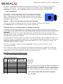
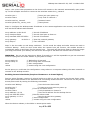
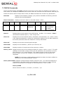
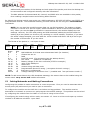
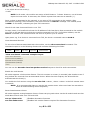
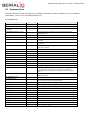
The format of the packet is: 110 bytes of data:
AP MAC
address
Chan
Bytes
0-5
6
7
8-9
10-13
14-15
16-17
18-31
32-59
60-91
92-93
94-110
RSSI
Size
6
1
1
2
4
2
2
13
26
32
2
16
Local
TCP port
Real
Time
Clock
Battery
Voltage
GPIO pins
time of
day
Version and
datecode
User
DEVICEID
Boot
time
SENSOR
pins
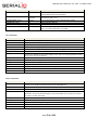
MAC adddress of AP that we are Associated with (for location )
Channel we are on.
RSSI
local TCP port# (for connecting into the WiSnap device )
RTC value
(MSB first to LSB last)
Battery Voltage on Pin 20 in millivolts (2755 for example )
value of the GPIO pins
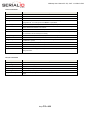
ASCII time
Version string with date code
Programmable Device ID string ( set option deviceid <string>)
Boot time in milliseconds.
Voltage readings of Sensors 0 thru 7 (enabled with “set opt format <mask>”)
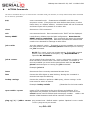
NOTE: To add sensor data to the UDP broadcast message, the sensors have to be enabled using the
sensor mask. set q sensor 0xff enables all sensors.
12 Joining Networks and Making Connections
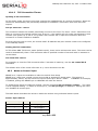
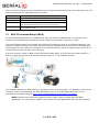
Configuring the module to make connections is a two set process. First you need to associate with a
access point (AP) and second you need to open a connection.
To configure the module over the WiFi link is a chicken and egg problem. The module must be
associated to a network to connect to it and program the network settings. This problem can be solved
by configuring the module from the UART or over the air using ad-hoc mode.
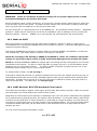
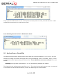
If configuring the module using ad-hoc mode, see section 15. Once in ad-hoc mode open up a telnet
window on IP address 169.254.1.1 port 2000
Page
47 of 83