1
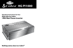
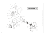
Installation and Operating
Instructions for the
Cobra™ Charger
208/240/480/550/575/600 Volts, 60Hz.
220/380/440 Volts, 50Hz.
I.B. 1424
IND 251
Rev M
Model:
Installed by:
S/N:
AC Input Voltage:
Date:
IMPORTANT
Read and understand your user's manual before installing, operating, or
servicing this product. DO NOT DESTROY THIS BOOK
Description of Model Number
T
C
12
600
B
VAC Input
AH Returned in 8 hours
Number of Cells in Battery
CobraTM Charger
Phase: S = Single
T = Three
TABLE OF CONTENTS
Safety Instructions ...........................................................................................................................................1
Location ...........................................................................................................................................................2
Installation........................................................................................................................................................2
Changing Voltages ..........................................................................................................................................3
Operation .........................................................................................................................................................6
Features and Functions...................................................................................................................................8
Viewing and Changing Parameters.................................................................................................................10
Maintenance ....................................................................................................................................................11
Service.............................................................................................................................................................11
Glossary...........................................................................................................................................................12
Replacement Parts ..........................................................................................................................................14
Drawings..........................................................................................................................................................18
Maintenance Record .......................................................................................................................................32
IMPORTANT SAFETY INSTRUCTIONS
1. This manual contains important safety and operating instructions. Before using the battery charger, read all
instructions, cautions, and warnings on the battery charger, the battery, and the product using the
battery.
2. This charger has been designed to only charge flooded, lead-acid batteries. (It cannot be adapted for sealed
batteries.)
3. Read and understand all setup and operating instructions before using the battery charger to prevent damage
to the battery and to the charger.
4. Do not touch non-insulated parts of the output connector or the battery terminals to prevent electrical shock.
5. During charge, batteries produce hydrogen gas which can explode if ignited. Never smoke, use an open
flame, or create sparks in the vicinity of the battery. Ventilate well when the battery is in an enclosed space.
6. Do not connect or disconnect the battery plug while the charger is on. Doing so will cause arcing and
burning of the connector resulting in charger damage or battery explosion.
7. Lead-acid batteries contain sulfuric acid which causes burns. Do not get in eyes, on skin, or on clothing. In
cases of contact with eyes, flush immediately with clean water for 15 minutes. Seek medical attention
immediately.
8. Only factory qualified personnel can service this equipment. For service, contact the nearest EnerSys Battery
authorized representative. (1-866-443-9433)
9. De-energize all AC and DC power connections before servicing the charger.
10. The charger is not for outdoor use.
11. Do not expose the charger to moisture. Operating conditions should be 0º to 104º F; 0 to 70% relative
humidity.
12. Do not operate the charger if it has been dropped, received a sharp hit, or otherwise damaged in any way.
13. For continued protection and to reduce the risk of fire, install chargers on a floor of non-combustible material
such as stone, brick, or grounded metal.
WARNING: The shipping pallet must be removed for proper and safe operation.
INSTRUCTIONS DE SÉCURITÉ IMPORTANTES
1. Ce manuel contient des informations importantes sur la sécurité et le fonctionnement. Avant d’utiliser le
chargeur de batterie, lire toutes les instuctions, les précautions et les avertissements sur le chargeur de
batterie, la batterie et le produit utilisant la batterie.
2. Ce chargeur est réglé en usine pour charger des batteries plomb-acide, noyées.
3. Lire et comprendre toutes les instructions de configuration et de fonctionnement avant d’utiliser le chargeur
de batterie pour éviter de détériorer la batterie et le chargeur.
4. Ne pas toucher les parties non isolées du connecteur de sortie ou les cosses de la batterie pour éviter une
électrocution.
5. Pendant la charge, les batteries produisent de l’hydrogène qui peut exploser s’il est enflammé. Ne jamais
fumer, utiliser une flamme vive, ou créer des étincelles à proximité de la batterie. Bien aérer si la batterie est
dans un lieu clos.
6. Ne pas connecter ou déconnecter la batterie pendant que la sortie du chargeur est sous tension. Cela
pourrait déçlencher un arc et brûler le connecteur entrainant des détériorations du chargeur.
7. Les batteries plomb-acide contiennent de l’acide sulfurique qui cause des brûlures. Éviter le contact avec les
yeux, la peau ou les vêtements. En cas de contact avec les yeux, rincer immédiatement à l’eau claire
pendant 15 minutes. Consulter immédiatement un médecin.
8. Seul le personnel d’usine qualifié peut entretenir cet équipement.
9. Supprimer la tension des connexions électriques alternatives et continues avant d’entretenir le chargeur.
10. Le chargeur ne doit pas être utilisé en plein-air.
11. Ne pas exposer le chargeur à l’humidite.
12. Ne pas utiliser le chargeur s’il est tombé, s’il a reçu un coup violent, ou s’il a été détérioré de toute autre
manière; appeler ou expédier l’appareil au centre d’entretien autorisé EnerSys General Battery le plus
proche.
13. Pour une protection continue it pour réduir le risque d’incendie, installer les chargeurs sur le sol ou sur un
matériau non-combustible comme la pierre, la brique, ou du metal mis à la terre.
1
CAUTION: DO NOT DESTROY THIS BOOK
This charger has been designed for simple and trouble free installation and operation. This manual has all the
instructions for installation, operation, maintenance, service, and parts ordering. Read carefully all the
instructions. Any deviation can cause serious and permanent damage. Failure to follow the instructions voids the
warranty.
LOCATION
Locate the charger in a clean, cool, dry, and well ventilated area where ambient temperature does not exceed
104OF (40OC). Mount the charger on a level and stable surface. There are holes in the base of the charger to
securely fasten it to wall mounting brackets or to a surface.
CAUTION: Operating at greater than 104OF ambient temperature will cause damage to the charger. Call
EnerSys General Battery for proper derating of the charger at temperatures greater than 104OF.
WARNING: Do not place flammable material on or near the charger. Place the charger on a nonflammable
surface such as concrete, stone or metal.
Leave ample space around the charger to allow for the free flow of air for convection cooling and to provide easy
accessibility. Air enters through the bottom of the charger and exits through the sides and back. Locate the
charger a minimum of 4 inches from any wall, and 6 inches from any other equipment.
For proper ventilation, do not store excess lengths of charger cables beneath the charger.
INSTALLATION
Connect this equipment to the proper AC supply as specified on the charger’s nameplate located on the outside
of the charger. Connection to any other voltage or frequency will cause equipment damage.
When selecting the size for an input wire, check the voltage setting, the input current draw, and the fuse size.
Reference this information in tables in this manual, or the nameplate of the charger, or the Fuse-Size label
located inside the charger next to the fuse block.
The size of the input wire must be in accordance with the National Electric Code (NEC) and other local codes.
This charger is for use with permanent wiring routed in an approved conduit.
WARNING: Only use copper conductors.
Make AC connections at the contactor or at the optional AC Disconnect switch labeled “AC Input Connections:
L1, L2, L3” located in the upper-right corner inside the charger. The AC connection wires can enter the cabinet
from the front, top, or bottom. The user must provide a suitable external AC disconnect switch from the AC power
supply to the charger to allow for safe servicing.
WARNING: There is a grounding lug inside the cabinet on the charger frame indicated as shown:
Connect to an external proven reliable ground source to prevent the possibility of electrical shock.
2
Stacking Multiple Chargers:
All CobraTM models stack up to three units high to conserve space.
WARNING: Fasten stacked chargers to wall to prevent tipping.
To stack chargers, follow these steps:
1.
Position the first charger so that a minimum of 4 inches of space is between the charger and any wall,
and 6 inches between the charger and any other equipment.
2.
Place the second charger on top of the first charger. Align the bolt holes of the top charger with the bolt
holes of the bottom charger.
3.
Fasten both charger cabinets together securely using 5/16” bolts and nuts.
4.
If a third charger is to be stacked, repeat steps 2 and 3 for the third charger.
5.
Attach stacked chargers to the wall using fastening devices suitable to the wall construction.
CHANGING INPUT VOLTAGE
When reconnecting for different input voltages, change the following:
1.
2.
3.
Jumpers on the terminal blocks.
Jumpers on the control transformer.
Input fuses.
Size the input wires for proper current draw. To make the changes refer to the tables in this manual or the FuseRating label in the charger. For each voltage setting refer to the diagrams, following, to verify the locations of
jumper wires on the AC terminal blocks. Check the control transformer wiring.
WARNING: Use only the proper AC fuse rating as shown in the Fuse-Rating label or tables in this manual. Use
of other size or rating voids the warranty and UL rating. Use of other fuse ratings will cause equipment
damage or create an unsafe operating condition. Be sure that the AC supply, the number of cells, and the
capacity of the battery to be charged correspond with the values shown on the charger’s nameplate rating.
WARNING: When changing AC jumper wires, tighten all leads securely into the terminal block. Tighten terminal
block screws to a torque value of 20 in-lbs. Loose connections will cause overheating and create an unsafe
operating condition.
Control Transformer: NOTE: The model "C" (575 volts) control transformer can only be connected in one way.
3
Three Phase, Model B
4
Three Phase, Model C
Three Phase, Model D
Three Phase, Model J
5
Single Phase, Model B
OPERATION
CobraTM charges batteries with the same cell size and ampere hour (AH) rating as listed on the charger’s
nameplate. If the battery’s AH rating is other than the AH rating specified on the charger’s nameplate, contact
your EnerSys General Battery service representative. Your service representative may be able to reconfigure the
charger to a different AH rating.
Factory Set Operating Instructions:
CobraTM is factory set for Auto-Start, DV/DT termination, Time-Voltage termination, and Auto-Equalize every fifth
cycle.
When AC power to the charger starts with no battery connected, these messages will display in rotation on the
front panel:
Conn (connect)
bAtt (battery)
When a battery is first connected to a powered-up charger, the display will show the message “Strt” which
indicates that the charger is starting.
In 5 seconds, the charger will start outputting Start Rate current, and the display will begin to show:
000A Charger current in amps.
0.000 Volts per cell.
0000 Amp hours returned to the battery.
00:00 Time spent in the charge cycle.
6
These values display in rotation for about 3 seconds each. Other messages display in this scrolling display as
needed. Reference the table following for a list of all messages shown in the display.
When the Gassing-Voltage point occurs (factory setting is 2.37 v/c), the 80% LED will light, the On LED remains
on, and the display will show the message, “80PC”.
After the current tapers to the Finish Rate current, the Finish LED will light. The LED’s that were lit before will
continue to be lit. Charging will continue until the time in Finish Rate meets the termination method’s
requirements. The charger will Auto Stop and the display will read “donE”.
When the charge cycle completes, the cycle counter increments by 1. If this was an Equalize charge cycle, the
cycle counter resets to 1.
When the number of charge cycles equals the Auto Equalize setting, the battery receives an Auto-Equalize
charge with the charge cycle continuing for 3 more hours. The display will continue to show the messages listed
above, with “EquL” added to the list. At the end of 3 hours the charger stops, and the display contains “donE”.
If the battery remains connected to the charger for 12 hours (factory default setting) after the completion of a
charge, a Refresh charge will automatically begin. A Refresh charge takes 20 minutes. A Refresh message will
display when the charge is being given, and a Charge Complete message will display when the Refresh charge
finishes.
Display Messages
Display
Message
000A
Amps
0.000
V/C
0000
AH
00:00
Hour:Minute
80PC
80 percent reached
Clrd
Fault cleared
CLrF
Clear fault
CodE
Pass code made
Conn bAtt
Connect battery
Cool
Battery cool down
CyCL
Equalize cycle
dELy
Set delay
donE
Charge completed
Mode
Charge
Charge
Charge
Charge
Charge
Select
Select
Select
Idle
Display
Select
Select
Display
EquL
FAtL
HdSt
Hour
OFF
ON
rEFS
rESt
StoP
Equalize charge.
Fatal fault
Hand start
Hour
Delay start off
Delay start on
Refresh
Restart
Charge stopped
Charge
Fault
Manual
Select
Select
Select
Charge
Fault
Display
Strt
Starting charge
Display
Description
Charge current in amps.
Volts per cell.
Amp hours returned to battery.
Time spent in charge cycle.
Displays when gassing voltage is reached.
Faults are cleared.
Clears fault message.
For EnerSys General Battery representatives.
Displays after charge stops while battery is in cool down period.
Displays after charge stops while battery is in cool down period.
Sets Equalize cycle count.
Delay start time.
Displays after a charge is complete and the cool down period is
over.
Displays when equalize charge begins.
Must take appropriate action before fault can be cleared.
Start pushbutton must be pressed to start charger.
Set amount of time for delayed start.
Turns off Delay Start function.
Turns on Delay start function to allow to set Delay Start time.
Displays when a refresh charge cycle begins.
Restarts automatically after AC power failure.
Displays when the stop pushbutton is pressed while a charge is in
progress.
Indicates that the charger is starting.
7
CHARGER FEATURES AND FUNCTIONS
Charge Mode - Automatic / Manual
This charger operates in either Automatic or Manual mode. The factory default setting is Automatic mode.
In Automatic mode, after detecting a battery, the control circuitry will Auto Start a Daily or an Equalize charge
cycle in 5 seconds. With a delay time programmed into the control, automatic mode will wait the specified
amount of time and then start the charge cycle.
In Manual mode, after detecting a battery, the display will contain “HdSt”. Pressing the Start pushbutton begins
the charge cycle.
Manual Equalize is in either Automatic or Manual modes. Push the Equal pushbutton to start an Equalize cycle.
AC Power Failure
The control circuitry detects AC power failures or brownout conditions. If this occurs, the control circuitry saves
key information concerning the charge cycle electronically, and the display contains “ACFt”. When power returns,
the control circuitry retrieves this information automatically, and the display will contain “reSt”. With a battery
connected to the charger, charging automatically continues after a random delay from 0 to 1 minute.
WARNING: With a battery connected to the charger at the moment power returns, the charge cycle continues
from the point it was before the power failure occurred.
Fault Condition Monitor
The charger control circuitry constantly monitors for several Fault conditions. If a fault should occur, the charge in
progress is interrupted and the Fault LED lights. A Fault message displays on the front control. Reference the
Fault messages following.
Determine the cause of the fault and correct it before resetting the Fault Condition monitor and trying to charge
the battery again. Clear the Fault code by using the CLEAR FAULTS (CLrF) select function, or by disconnecting
and re-connecting the battery.
If the fault code is “t-2F” or “t-1F”, then you must disconnect and reconnect the battery twice. Disconnecting the
battery the second time resets the timers.
Fault Messages
Messages
Description
ACFt
Displays if the AC line voltage falls below 10% of
the nominal line voltage.
-dLt
Displays when the battery voltage satisfies a
decreasing slope; related to the sample period.
Eror
Displays if it detects battery voltage above 3.00
volts per cell before charger starts.
Hi A
Displays if it detects DC output current for longer
than 5 seconds above 27% of the AH setting.
8
Possible Causes
Check the complete contactor coil string and
associated wiring.
AC brownout.
AC failure.
Bad AC fuse(s).
Battery charge, battery problems such as:
cell problem.
heating problem.
hot battery.
Battery with a larger cell size than charger’s
nameplate rating.
Wrong charger cell size setting. Sulfated battery.
Battery problem.
Severe line shifts.
AC taps set to 208 with 240 VAC applied.
SCR locked on.
Messages
HiAH
Description
Displays when 220% of the charger’s AH rating
have been delivered to the battery.
Hi b
Displays if it detects battery voltage above 2.40
volts per cell before charger starts. Displays
when the battery reaches 3 v/c of the battery cell
size the charger has been set to. Fault LED will
be lit.
Displays if DC output current falls 30% below
finish current setting for longer than 5 seconds.
Lo A
Lo b
Displays if it detects battery voltage below 1.7
volts per cell before charger starts.
no b
No battery voltage when expected.
Fault Messages
Messages
Description
OPEn
Displays if DC current falls below the minimum
setting.
t-1F
Displays when the charger does not reach the
80% point within 9 hours.
t-2F
Fails to complete the charge cycle within 15
hours (factory default) of the start of charge.
Up b
Displays if the up battery or finish rate reject is
satisfied.
9
Possible Causes
Battery does not match AH range on nameplate.
Charger’s AH rating programmed wrong.
SCR failure during last use.
Battery with a larger cell size than charger’s
nameplate rating.
Charger cell size programmed wrong.
Wrong charger cell size setting.
Loose connection in DC output string (shunt,
cable, etc.).
Battery intercell connector problem.
Severe line shifts.
Severely sulfated battery.
Battery cell size smaller than charger’s
nameplate rating.
Charger cell size programmed wrong.
Wrong charger cell size setting.
Charger output shorted.
Capacitor shorted.
Possible Causes
DC cable disconnected during charge.
DC fuse open.
Loose connection in output string.
Battery problem.
Reverse polarity.
Check charger/battery connector.
Shorted caps.
Battery’s AH larger than the charger’s AH rating.
Battery temperature too high.
80% point set too high.
Battery’s cell size smaller than charger’s cell
size.
Battery AH rating larger than the charger AH
rating.
Battery temperature too high.
Defective AC fuse.
Capacitor.
Diode.
Charged battery.
Cold battery.
Sulfated battery.
80% point set too low.
Battery cell size larger than charger cell size.
VIEWING AND CHANGING PARAMETERS
Two modes of operation are available:
1.
2.
Display mode, used to view charge cycle data.
Select mode, which is used to clear faults, enable delay start, equalize count, etc.
Display Mode
Push the Up- and Down-Arrow pushbuttons to display the information described in the following table. The
Display mode is available whether or not the charger is in a charge cycle.
Display Mode Information
Message
Description
000A
Displays the DC current to the battery.
0.000
Displays the voltage per cell.
0000
Displays the cumulative AH returned to the battery.
00:00
Displays the time spent in the current charge cycle.
00
Displays the cell size of the battery.
0000
Displays the battery AH rating.
Select Mode
To enter the Select mode, press the Select pushbutton. “CLrF” will appear in the display. Use the Up- and
Down-Arrow pushbuttons to scroll through the variables. To exit Select mode and return to Display mode, press
the Equal pushbutton.
The following table describes the variables you can change in Select mode. The following sections describe how
to change each variable.
NOTE: Select mode is not available during a charge cycle.
Select Mode Variables
Display
Description
CLrF
Clears fault messages.
Clrd
Faults are cleared.
dELy
Delay start time. Used when the charger is set to Automatic mode. Determines how long the
charger will wait before beginning the charge cycle after the control circuitry determines that a
battery is connected.
EquL
Set Equalize charge. Determines when an Equalize charge cycle will automatically occur.
The Equalize counter determines how often an Equalize charge cycle will occur.
When the cycle counter = Equalize counter, an Equalize charge cycle occurs, and after the
Equalize charge completes, the cycle counter will be reset to 1.
CodE
For EnerSys General Battery service representatives.
Setting the Delay Start Parameter
“dELy” specifies the amount of time the charger will wait before beginning a charge cycle.
1.
2.
3.
4.
5.
6.
Press the Select pushbutton if you want to view or change the value of this parameter. After the Select
pushbutton is pressed, ON or OFF will display.
To turn off Automatic delay, put OFF in the display, and press the Select pushbutton.
To turn on Automatic delay or to change the time of the delay, put ON in the display and press the Select
pushbutton.
To view or change the parameter, press the Select button once again. A time (hours, minutes) will now
display.
Use the Up- and Down-Arrow keys to change the value in the display.
Press the Select pushbutton to save the new value you just entered.
10
7.
Press the Equal pushbutton twice to exit the User level.
Setting the Equalize Parameter
If the charger is running in Automatic mode, an Equalize charge cycle will begin when the cycle counter equals
the Equalize counter. After an Equalize charge cycle, the cycle counter resets to 1, and the Equalize parameter
will remain the same.
To change an Equalize parameter, follow these steps:
1.
2.
3.
4.
To view or change the value of the Equalize Counter parameter, press the Select pushbutton to display
the value of the parameter.
Use the Up- and Down-Arrow keys to change the value in the display.
Press the Select pushbutton to save the new value you just entered.
Press the Equal pushbutton twice to return to Select mode.
Setting the Clear Fault/Faults are Clear Parameter
To clear a fault or to verify if the fault monitor contains a fault code, please follow these steps.
1.
Use the Up- and Down-Arrow pushbuttons to scroll through the variables. display “CLrF” or “Clrd”.
2.
a.
If the display shows “Clrd”, then there are no faults in the fault monitor.
b.
If “CLrF” (clear faults) displays, press the Select pushbutton to clear the faults.
If FAtL displays when using the CLrF function, then you must disconnect and reconnect the battery twice,
or push the Select pushbutton after unplugging battery. the only Faults that should cause this are t-1F
and t-2F.
3.
Pressing the Equal pushbutton will exit you from the Select mode, but will NOT clear the faults.
Pass Code Parameter
The pass code parameter is available to qualified and authorized representatives of EnerSys General Battery
only. Any attempt to enter and modify variables by unauthorized persons WILL void the warranty and may cause
damage to the charger and/or battery.
MAINTENANCE
This charger requires a minimum of maintenance. Connections and terminals should be kept clean and tight.
The unit should be periodically cleaned with an air hose to prevent any excessive dirt build up on components.
Care should be taken not to bump or move any adjustments during cleaning. Make sure that both the AC lines
and the battery are disconnected before cleaning. The frequency of this type of maintenance depends on the
environment in which this unit is installed.
SERVICE
For service, contact your sales representative or call:
1-866-443-9433 (United States)
1-800-693-9433 or
905-790-1212 (Canada)
Or visit us at our website: www.enersysmp.com
11
Glossary of CobraTM Terminology:
Definitions of terms used as they apply to the CobraTM charger. Use in other applications may or may not have
different meanings.
AMP HOUR (AH)
Amount of amps delivered over a period of time. Example: 100 amp
draw of 2 hours equals 200 AH.
AUTOMATIC MODE
Factory enable. After a 5 second delay, the charger automatically
starts when it detects DC voltage within the start range parameters.
charge automatically stops when one of the termination methods or
fault conditions is met.
COBRATM FINISH
Programmable constant current finish rate. Factory setting is 4.5 amps
per 100 AH of charger nameplate rating. It provides superior recharge
capability because it is not affected by battery age, condition or
temperature.
COOL DOWN
Programmable amount of time after charger termination before Charge
Complete LED lights. Factory setting is enabled an 6 hours in length.
DELAY START
Delays start of charge in one minute increments up to 18 hours and 12
minutes. Factory setting is off and should be programmed at user site
for specific application. Useful for energy management or to allow
battery to warm up or cool down to nominal 77o F before charging.
DV/DT TERMINATION METHOD
Change of voltage over change of time. Factory setting is enable.
Sampling period is programmable to increase or decrease amount of
charge time.
FAULT MONITOR
Displays fault messages to ensure safe charger operation to prevent
battery or charger damage. Various fault conditions are constantly
monitored. Some may disable the charger, others warn of possible
problems.
FERRORESONANT TRANSFORMER
Transformer design utilizing capacitance in the secondary circuit.
Battery volts determines the DC output. Regulation of output current
requires no electronics or sophisticated controls thus ensuring troublefree and fail-safe operation.
FINISH RATE REJECT
If battery reaches CobraTM finish within 1 minute of start, charge
terminates in 10 minutes.
GASSING VOLTAGE
Point in charger cycle when battery has reached 80% recharge, often
referred to as “80% point”. Factory setting is 2.37 v/c and is
programmable for various operating conditions.
LED
Light emitting diode. Used as indicator lights on front panel.
MANUAL MODE
Factory disabled. CobraTM may be programmed to require operator to
push the start button. Charge automatically stops when one of the
termination methods or fault conditions is met.
MODE
Phase or area of charger cycle; display, select, charge.
12
NAMEPLATE RATING
Unalterable factory configuration of charger capabilities, I.E., cell size,
maximum DC output,. AH capacity.
OVERRIDE TIMERS
Prevents damage to the battery if certain conditions are not met.
Factory settings are 9 hours to gassing voltage and 15 hours maximum
charge time. They are programmable to compensate for operating and
battery conditions.
PARAMETER
Function inside a mode such as equalize, delay, pass code, etc.
RANDOM DELAY START
After an AC brownout or power failure, charger momentarily delays to
help reduce peak power demands. Chargers delay in one minute
increments up to a maximum of 10 minutes. Delay time increment is
not programmable and determined at the time of manufacture. Factory
setting is enable.
REFRESH
If a battery remains connected for a specified amount of time after
charge completion, a brief recharge takes place. Factory setting is
enable, 12 hours wait time,. and 20 minutes in duration. All variables
are programmable.
SCR
Silicon controlled rectifier. Used to provide CobraTM finish.
SELECT
The charger operation mode used to view or change parameters.
START RATE
Factory design regulating DC output current to approximately 20 amps
per 100 AH of nameplate rating. Severe AC line shifts of greater than
+/- 10% and battery voltage effect start current. Age, condition,
temperature, and state of discharge determine battery voltage.
TERMINATION METHODS
Factory setting is both T/V and DV/DT. Each can be used
independently. It also utilizes several override times and fault monitors
to ensure safe charger operation.
TIME VOLTAGE TERMINATION
METHOD (T/V)
Amount of time until charger terminates after reaching gassing voltage.
Factory setting enabled and 4 hours in length. Time is programmable
to compensate for various operating conditions.
UP BATTERY REJECT
If battery reaches gassing voltage within 6 seconds of start, charge
terminates in 10 minutes.
VARIABLE
Individual item inside a parameter: Examples: Equalize -cycle; Delay on/off; Pass code - Cool down, random delay start, refresh, etc.
VOLTS PER CELL (V/C)
Average reading of volts per cell as calculated by measuring battery
terminal volts and divided by cell setting.
WAIT TIME
Amount of programmable time (usually in minutes) until a particular
function takes place, i.e. delay, equalize, refresh, etc.
13
REPLACEMENT PARTS
Model Number Suffix
B
C
J
D
SC COMMON PARTS
Base
013-328-1DG
Door
X052-242VB
Side
X057-328-2DG
Top
X057-328-4DG
Wire Group
X1106-14-28
2 Amp Fuse
X014-7-28
PC Mntg Panel
159-6-2272VB
Display Board
X1060-73-1
Term Blk, 10 Pole
256-D-33
Voltages
208/240/480 (60 Hz)
575 (60 Hz)
480/550/600 (60 Hz)
220/380/440 (50 Hz)
Panel
Latch
Back
Snubber Ass'y
PC Board
Membrane Switch
SCR
Term Blk, 6 Pole
Conversion Kit
X052-242VB
X044-1-30
X057-328-3DG
X1100-214-2
X1060-64-2
X002-46-5
R507-17-15
256-D-32
X225-91-1
TC COMMON PARTS
Base
013-326-1DG
Panel
X052-241VB
Door
X054-326-6MG
Latch
X044-1-30
Side, Left
X057-326-3DG
Side, Right
X057-326-4DG
Back
X057-326-2DG
Top
X057-326-5DG
Snubber Ass'y
X1100-214-2
Wire Group
X1106-14-9
PC Board
X1060-64-2
2 Amp Fuse
X014-7-28
Membrane Switch
X002-46-5
PC Mntg Panel
159-6-2272VB
SCR
R507-17-15
Display Board
X1060-73-1
Term Blk, 6 Pole
256-D-32
Conversion Kit, TC to TCG X225-91-1
Line contactor: X129-62-53 (40Amp), and X129-62-54 (60Amp)
Control transformers: X127-61-1 (B model), X127-61-2 (C model), X127-61-3 (D model), and X127-61-4 (J
model)
Match the capacitor value under each model and use the following correlation to order by part number.
029-1362.5MFD 029-136-18D 4MFD
029-136-12D 10MFD
029-136-14D 15MFD
16D
029-1363MFD
029-136-11D 5MFD
029-136-13D 12MFD
029-136-15D 18MFD
17D
New capacitor brackets should be requested when ordering these capacitors.
Single Phase, Model B
Model
6-450B
6-550B
6-600B
12-225B
12-380B
12-550B
12-600B
12-775B
12-865B
18-550B
18-600B
18-680B
Main Transformer Cap Value
1
X127-63-204A
X127-63-206A
X127-63-206A
X127-63-213A
X127-63-215A
X127-63-217A
X127-63-123A
X127-64-171A
X127-64-241A
X127-64-137A
X127-64-138A
X127-64-724A
3MFD
12MFD
12MFD
10MFD
5MFD
10MFD
15MFD
10MFD
10MFD
2.5 MFD
18MFD
10MFD
Cap
Value 2
3MFD
n/a
n/a
n/a
4MFD
3MFD
n/a
10MFD
12MFD
18MFD
3MFD
15MFD
208/240V
AC Fuse
208/240V
Fuse Value
X014-4-14
X014-4-9
X014-4-9
X014-4-14
X014-4-12
X014-4-6
X014-4-6
X014-4-1
X014-4-15
X014-4-17
X014-4-17
X014-4-2
14
10
15
15
10
20
30
30
35
40
45
45
50
480V AC
Fuse
X014-4-10
X014-4-10
X014-4-10
X014-4-10
X014-4-19
X014-4-9
X014-4-9
X014-4-12
X014-4-12
X014-4-12
X014-4-12
X014-4-16
480V Fuse
Value
6
6
6
6
8
15
15
20
20
20
20
25
18-775B
18-865B
24-450B
X127-64-724A
X127-64-210A
X127-64-145A
15MFD
15MFD
10MFD
10MFD
18MFD
10MFD
X014-4-2
X014-4-11
X014-4-17
50
60
45
X014-4-16
X014-4-6
X014-4-12
25
30
20
Three Phase, Model B
Model
12-450B
12-550B
12-600B
12-680B
12-775B
12-865B
12-960B
12-1050B
18-380B
18-600B
18-680B
18-775B
18-865B
18-960B
18-1050B
18-1200B
18-1400B
18-1500B
24-450B
24-550B
24-600B
24-680B
24-775B
24-865B
24-960B
24-1050B
36-380B
36-550B
36-775B
40-380B
40-450B
40-550B
Main Transformer
X127-63-213A/B
X127-63-214A/B
X127-63-214A/B
X127-63-215A/B
X127-63-215A/B
X127-63-216A/B
X127-63-217A/B
X127-63-217A/B
X127-63-130A/B
X127-64-132A/B
X127-64-134A/B
X127-64-134A/B
X127-64-135A/B
X127-64-137A/B
X127-64-137A/B
X127-64-138A/B
X127-64-724A/B
X127-64-724A/B
X127-63-140A/B
X127-63-142A/B
X127-63-142A/B
X127-64-144A/B
X127-64-144A/B
X127-64-145A/B
X127-64-147A/B
X127-64-147A/B
X127-64-342A/B
X127-64-151A/B
X127-64-193A/B
X127-64-341A/B
X127-64-352A/B
X127-64-352A/B
Cap
value 1
Cap
value 2
208/240V. 208/240V.
AC Fuse Fuse value
10MFD
n/a
X014-4-6
5MFD 2.5MFD X014-4-9
5MFD 2.5MFD X014-4-9
5MFD
4MFD X014-4-12
5MFD
4MFD X014-4-12
12MFD
n/a
X014-4-16
10MFD 3MFD X014-4-6
10MFD 3MFD X014-4-6
4MFD
4MFD X014-4-12
10MFD
n/a
X014-4-16
10MFD 3MFD X014-4-6
10MFD 3MFD X014-4-6
15MFD
n/a
X014-4-6
18MFD
n/a
X014-4-15
18MFD 2.5MFD X014-4-15
18MFD 3MFD X014-4-2
10MFD 15MFD X014-4-2
10MFD 15MFD X014-4-2
10MFD
n/a
X014-4-16
15MFD
n/a
X014-4-6
15MFD
n/a
X014-4-6
18MFD
n/a
X014-4-15
18MFD
n/a
X014-4-15
10MFD 10MFD X014-4-2
12MFD 12MFD X014-4-2
12MFD 12MFD X014-4-2
15MFD
n/a
X014-4-15
12MFD 12MFD X014-4-11
12MFD 15MFD X014-4-11
15MFD
n/a
X014-4-15
12MFD 12MFD X014-4-11
12MFD 12MFD X014-4-11
15
30
15
15
20
20
25
30
30
20
25
30
30
30
40
40
50
50
50
25
30
30
40
40
50
50
50
40
60
60
40
60
60
480V. AC
Fuse
X014-4-24
X014-4-19
X014-4-19
X014-4-14
X014-4-14
X014-4-24
X014-4-9
X014-4-9
X014-4-14
X014-4-14
X014-4-9
X014-4-9
X014-4-9
X014-4-12
X014-4-12
X014-4-16
X014-4-16
X014-4-16
X014-4-24
X014-4-9
X014-4-9
X014-4-12
X014-4-12
X014-4-16
X014-4-16
X014-4-16
X014-4-12
X014-4-6
X014-4-6
X014-4-12
X014-4-6
X014-4-6
480V.
Fuse
value
12
8
8
10
10
12
15
15
10
10
15
15
15
20
20
25
25
25
12
15
15
20
20
25
25
25
20
30
30
20
30
30
Three Phase, Model C
Cap
value 1
Model
Main Transformer
12-550C
18-775C
18-865C
18-960C
18-1050C
24-600C
24-960C
24-1050C
X127-63-214TA/TB
X127-64-134TA/TB
X127-64-135TA/TB
X127-64-137TA/TB
X127-64-137TA/TB
X127-63-142TA/TB
X127-64-147TA/TB
X127-64-147TA/TB
Cap
value 2
575V. AC
Fuse
5MFD 2.5MFD X014-4-10
10MFD 3MFD X014-4-14
15MFD
n/a
X014-4-9
18MFD
n/a
X014-4-12
18MFD
n/a
X014-4-12
15MFD
n/a
X014-4-9
12MFD 15MFD X014-4-16
12MFD 15MFD X014-4-16
Three Phase, Model D
Model
12-865D
12-960D
18-680D
18-775D
18-1050D
Main Transformer
X127-65-216A5E/B5E
X127-63-217A5E/B5E
X127-63-134A5E/B5E
X127-63-134A5E/B5E
X127-64-137A5E/B5E
Cap
Cap
value 1 value 2
220V AC
Fuse
12MFD
n/a
18MFD
n/a
18MFD
n/a
18MFD
n/a
10MFD 12MFD
X014-4-16
X014-4-6
X014-4-6
X014-4-1
X014-4-15
380/440V
Fuse
value
X014-4-9
15
X014-4-9
15
X014-4-9
15
X014-4-12
20
X014-4-12
20
220V Fuse 380/440V
value
AC Fuse
25
30
30
35
40
Single and Three Phase, Model J
Phase
Model
Main Transformer
1ph
3ph
3ph
3ph
3ph
3ph
3ph
18-775J
18-775J
18-865J
24-600J
24-680J
24-775J
24-865J
X127-64-724AJ
X127-63-134AJ/BJ
X127-64-135AJ/BJ
X127-63-142AJ/BJ
X127-64-144AJ/BJ
X127-64-144AJ/BJ
X127-64-145AJ/BJ
3ph
3ph
24-1050J X127-64-147AJ/BJ
36-775J X127-64-193AJ/BJ
Cap
Cap
value 1 value 2
15MFD 18MFD
4MFD
n/a
15MFD
n/a
15MFD
n/a
18MFD
n/a
18 MFD
n/a
10MFD 12MFD
15MFD
12MFD
16
480/550/600V
AC Fuse
X014-4-16
X014-4-9
X014-4-9
X014-4-9
X014-4-12
X014-4-12
X014-4-16/
X014-4-12
n/a
X014-4-16
15MFD X014-4-16
Fuse
value
25
15
15
15
20
20
25/20
25
25
Parts by Output
Phase
1ph
1ph
1ph
1ph
1ph
1ph
1ph
1ph
1ph
1ph
1ph
1ph
1ph
1ph
1ph
3ph
3ph
3ph
3ph
3ph
3ph
3ph
3ph
3ph
3ph
3ph
3ph
3ph
3ph
3ph
3ph
3ph
3ph
3ph
3ph
3ph
3ph
3ph
3ph
3ph
3ph
3ph
3ph
3ph
A ll M o d e ls
6 -4 5 0
6 -5 5 0
6 -6 0 0
1 2 -2 2 5
1 2 -3 8 0
1 2 -5 5 0
1 2 -6 0 0
1 2 -7 7 5
1 2 -8 6 5
1 8 -5 5 0
1 8 -6 0 0
1 8 -6 8 0
1 8 -7 7 5
1 8 -8 6 5
2 4 -4 5 0
1 2 -4 5 0
1 2 -5 5 0
1 2 -6 0 0
1 2 -6 8 0
1 2 -7 7 5
1 2 -8 6 5
1 2 -9 6 0
1 2 -1 0 5 0
1 8 -3 8 0
1 8 -6 0 0
1 8 -6 8 0
1 8 -7 7 5
1 8 -8 6 5
1 8 -9 6 0
1 8 -1 0 5 0
1 8 -1 2 0 0
1 8 -1 4 0 0
1 8 -1 5 0 0
2 4 -4 5 0
2 4 -5 5 0
2 4 -6 0 0
2 4 -6 8 0
2 4 -7 7 5
2 4 -8 6 5
2 4 -9 6 0
2 4 -1 0 5 0
3 6 -3 8 0
3 6 -5 5 0
3 6 -7 7 5
D C fu s e
X 0 1 4 -1 1 -1
X 0 1 4 -1 1 -3
X 0 1 4 -1 1 -3
X 0 1 4 -1 1 -1 8
X 0 1 4 -1 1 -2
X 0 1 4 -1 1 -3
X 0 1 4 -1 1 -3
X 0 1 4 -1 1 -9
X 0 1 4 -1 1 -1 0
X 0 1 4 -1 1 -3
X 0 1 4 -1 1 -3
X 0 1 4 -1 1 -9
X 0 1 4 -1 1 -9
X 0 1 4 -1 1 -1 0
X 0 1 4 -1 1 -1
X 0 1 4 -1 1 -1
X 0 1 4 -1 1 -3
X 0 1 4 -1 1 -3
X 0 1 4 -1 1 -9
X 0 1 4 -1 1 -9
X 0 1 4 -1 1 -1 0
X 0 1 4 -1 1 -1
X 0 1 4 -1 1 -1
X 0 1 4 -1 1 -3
X 0 1 4 -1 1 -3
X 0 1 4 -1 1 -9
X 0 1 4 -1 1 -9
X 0 1 4 -1 1 -1 0
X 0 1 4 -1 1 -1 6
X 0 1 4 -1 1 -1 3
X 0 1 4 -1 1 -1 3
X 0 1 4 -1 1 -1 6
X 0 1 4 -1 1 -1 6
X 0 1 4 -1 1 -3
X 0 1 4 -1 1 -3
X 0 1 4 -1 1 -3
X 0 1 4 -1 1 -9
X 0 1 4 -1 1 -9
X 0 1 4 -1 1 -1 0
X 0 1 4 -1 1 -1
X 0 1 4 -1 1 -1
X 0 1 4 -3 0 -3
X 0 1 4 -3 0 -3
X 0 1 4 -3 0 -5
D C va lu e
125 A
150 A
150 A
60 A
100 A
150 A
150 A
200 A
225 A
150 A
150 A
200 A
200 A
225 A
125 A
125 A
150 A
150 A
200 A
200 A
225 A
2x 125 A
2x 125 A
150 A
150 A
200 A
200 A
225 A
250 A
350 A
350 A
2x 250 A
2x 250 A
150 A
150 A
150 A
200 A
200 A
225 A
2x 125 A
2x 125 A
FW A 150A
FW A 150A
FW A 200A
17
H e a t S in k
R 5 2 1 -9 5 -5 0
R 5 2 1 -9 5 -5 0
R 5 2 1 -9 5 -5 0
R 5 2 1 -9 5 -4 0
R 5 2 1 -9 5 -5 0
R 5 2 1 -9 5 -5 0
R 5 2 1 -9 5 -5 0
R 5 2 1 -9 5 -6 0
R 5 2 1 -9 5 -6 0
R 5 2 1 -9 5 -5 0
R 5 2 1 -9 5 -5 0
R 5 2 1 -9 5 -9 0
R 5 2 1 -9 5 -6 0
R 5 2 1 -9 5 -6 0
R 5 2 1 -9 5 -5 0
R 5 2 1 -9 3 -1 0
R 5 2 1 -9 3 -1 0
R 5 2 1 -9 3 -1 0
R 5 2 1 -9 5 -7 0
R 5 2 1 -9 5 -7 0
R 5 2 1 -9 3 -2 0
R 5 2 1 -9 3 -2 0
R 5 2 1 -9 3 -2 0
R 5 2 1 -9 3 -1 0
R 5 2 1 -9 3 -1 0
R 5 2 1 -9 5 -7 0
R 5 2 1 -9 5 -7 0
R 5 2 1 -9 3 -2 0
R 5 2 1 -9 3 -2 0
R 5 2 1 -9 3 -2 0
R 5 2 1 -9 3 -3 0 A
R 5 2 1 -9 3 -3 0 A
R 5 2 1 -9 3 -3 0 A
R 5 2 1 -9 3 -1 0 A
R 5 2 1 -9 3 -1 0 A
R 5 2 1 -9 3 -1 0 A
R 5 2 1 -9 5 -7 5 A
R 5 2 1 -9 5 -7 0 A
R 5 2 1 -9 3 -2 0 A
R 5 2 1 -9 3 -2 0 A
R 5 2 1 -9 3 -2 0 A
R 5 2 1 -9 8 -1 0 A
R 5 2 1 -9 8 -1 0 A
R 5 2 1 -9 8 -2 0 A
D io d e
R 5 0 7 -1 2 -1
R 5 0 7 -1 2 -1
R 5 0 7 -1 2 -1
R 5 0 7 -1 2 -6 8
R 5 0 7 -1 2 -1
R 5 0 7 -1 2 -1
R 5 0 7 -1 2 -1
R 5 0 7 -1 2 -2
R 5 0 7 -1 2 -2
R 5 0 7 -1 2 -1
R 5 0 7 -1 2 -1
R 5 0 7 -1 2 -1
R 5 0 7 -1 2 -2
R 5 0 7 -1 2 -2
R 5 0 7 -1 2 -1
R 5 0 7 -1 2 -6 8
R 5 0 7 -1 2 -6 8
R 5 0 7 -1 2 -6 8
R 5 0 7 -1 2 -6 8
R 5 0 7 -1 2 -6 8
R 5 0 7 -1 2 -1
R 5 0 7 -1 2 -1
R 5 0 7 -1 2 -1
R 5 0 7 -1 2 -6 8
R 5 0 7 -1 2 -6 8
R 5 0 7 -1 2 -6 8
R 5 0 7 -1 2 -6 8
R 5 0 7 -1 2 -1
R 5 0 7 -1 2 -1
R 5 0 7 -1 2 -1
R 5 0 7 -1 2 -2 A
R 5 0 7 -1 2 -2 A
R 5 0 7 -1 2 -2 A
R 5 0 7 -1 2 -6 8 A
R 5 0 7 -1 2 -6 8 A
R 5 0 7 -1 2 -6 8 A
R 5 0 7 -1 2 -6 8 A
R 5 0 7 -1 2 -6 8 A
R 5 0 7 -1 2 -1 A
R 5 0 7 -1 2 -1 A
R 5 0 7 -1 2 -1 A
R 5 0 7 -1 2 -6 8 A
R 5 0 7 -1 2 -6 8 A
R 5 0 7 -1 2 -6 8 A
Shunt
X 1 1 7 -8 -1 2
X 1 1 7 -8 -1 2
X 1 1 7 -8 -1 2
X 1 1 7 -8 -1 2
X 1 1 7 -8 -1 2
X 1 1 7 -8 -1 2
X 1 1 7 -8 -1 2
X 1 1 7 -8 -1 3
X 1 1 7 -8 -1 3
X 1 1 7 -8 -1 2
X 1 1 7 -8 -1 2
X 1 1 7 -8 -1 3
X 1 1 7 -8 -1 3
X 1 1 7 -8 -1 3
X 1 1 7 -8 -1 2
X 1 1 7 -8 -1 2
X 1 1 7 -8 -1 2
X 1 1 7 -8 -1 2
X 1 1 7 -8 -1 3
X 1 1 7 -8 -1 3
X 1 1 7 -8 -1 3
X 1 1 7 -8 -1 3
X 1 1 7 -8 -1 3
X 1 1 7 -8 -1 2
X 1 1 7 -8 -1 2
X 1 1 7 -8 -1 3
X 1 1 7 -8 -1 3
X 1 1 7 -8 -1 3
X 1 1 7 -8 -1 3
X 1 1 7 -8 -1 3
X 1 1 7 -8 -1 3
X 1 1 7 -8 -1 3
X 1 1 7 -8 -1 3
X 1 1 7 -8 -1 2
X 1 1 7 -8 -1 2
X 1 1 7 -8 -1 2
X 1 1 7 -8 -1 3
X 1 1 7 -8 -1 3
X 1 1 7 -8 -1 3
X 1 1 7 -8 -1 3
X 1 1 7 -8 -1 3
X 1 1 7 -8 -1 2
X 1 1 7 -8 -1 2
X 1 1 7 -8 -1 3
SCHEMATIC, 3 PH, 208/240/480V, 60 Hz
18
19
SCHEMATIC, 1PH, 120V
20
21
22
23
24
25
1
2 3 4
5
26
27
1
2 3 4 5
28
29
1
2 3 4
5
30
31
Maintenance
1. Installation
Model:
S/N:
AC Input Voltage:
Date:
Installed by:
2. Modifications to Factory Settings
Date
Variable
3. Service
Date
Change
Description
32
Service Technician
Service Technician