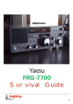
1
Yaesu
FT-901DM
&
FT-902DM
Survival Guide
This manual was downloaded from Fox Tango International
http://www.foxtango.org
PAØPGA
1
Contents:
Introduction
Specifications
History of the FT-901D/DM and FT-902D/DM series
Maintenance
901/902 modules
901/902 accessoires
Serial numbers
FT-901D Revival story
Improving the FT-901/902
The 6146 family of tubes
Ratings for the FT-901/902
Counter replacement module
VFO stability story
Interesting sites
FT-901 and FT-902 Trimmer boards
2
PAØPGA
PAØPGA
PAØPGA
PAØPGA
LA8AK
K9STH
eHam.net
JA2SVH
WB5TKA
This manual was downloaded from Fox Tango International
http://www.foxtango.org
page 3
page 4
page 5
page 7
page 9
page 14
page 15
page 16
page 22
page 25
page 27
page 31
page 32
page 15
page 33
PAØPGA
The
FT-901DM and FT-902DM
Survival Guide
Introduction:
I will not go in detail on every nut and bolt of this transceiver, but only highlight my own experience and the experiences
of fellow Hams.
This Guide is a collection of found facts from all over the Internet and other sources, collected in one volume for the
benefit of the many FT-901/902 users who try to keep their equipment in optimal condition. It is not, however a
modification guide for the “purists”, who want to raise the “quality” of their sets, and by doing so ruin a beautiful piece of
equipment. They have to do their own research.
The Guide is by no means complete, and if you have something to contribute, feel free to drop me a e-mail at:
http://[email protected] or post it on the Fox-Tango forum.
I want to update this Guide if the need arises. The suggested modifications are always small and have a special purpose:
to keep HF from the microphone, or a better protection of the power supply, to name a few.
Included are also related articles, such as the excellent 6146B article by Glen Zook, and others, who are of interest for all
the FT-901/902 users.
For your information: There is also a FRG-7700 Survival Manual and a FT-101ZD Survival Manual.
You find them all on the Fox-Tango library for a free download. see http://foxtang.org
I hope you will find something useful in this guide.
73, Wim Penders PAØPGA
This manual was downloaded from Fox Tango International
http://www.foxtango.org
PAØPGA
3
Specifications FT-901DM
Type:
Frequency Range:
Mode:
RF Power output:
Sensitivity:
Selectivity:
Image rejection:
Display
Power:
Current drain DC:
Impedance:
Dimensions
Weight:
Manufactured:
Accessoires:
4
Amateur HF transceiver
10-160m,
SSB/CW/FSK/AM/FM
SSB/CW
AM/FM
SSB/CW:
AM/FM:
SSB
AM
CW
Mains,
13.8 Vdc
Receive:
Transmit:
50 – 75 ohms,
FTV-901R
FV-901DM
FL-2100Z
SP-901P
FC-901
FC-902
YO-901
MK3
(early models had no WARC bands)
100W
35W
0.25 uV (10db S/n)
0.5 uV (10db S/n)
2.4 khz @ -6db,
6 khz @ -6db,
600 or 300 hz,
- 60 db (160-15m)
analog + digital dial
4 khz @ -60db
(with optional filter)
(with optional filters)
- 50 db (10m)
100-235 V ac 50/60hz
Only DM models, DC-DC converter option for all others
5.5 Amps,
(1.1 Amps with heater off)
Max. 21 Amps.
SO-239 connector
345 * 157 * 326 mm (W*H*D)
18 kilograms
1978 – 1982
VHF/UHF/Oscar Transverter
Synthesised scanning external VFO
Linear Amplifier 1200W SSB, 1000W CW
External Speaker/Phone Patch
Antenna Coupler
Antenna Coupler with WARC Bands
Multiscope
This manual was downloaded from Fox Tango International
http://www.foxtango.org
PAØPGA
History of the FT-901/902 series transceivers.
The FT-901D/DM was introduced in early 1978, and was a immediate success on the amateur market. It is the real
ascent of the highly successful FT-101 series transceivers, that Yaesu introduced in 1968, and produced in ever increasing
numbers until 1979, when the last of this series (FT-101F) were sold.
By this time every amateur had learned that this and other Japanese “riceboxes” had a number of never-before possible
features, and a good quality. The new transceivers had also very good signal on the air. All this and a very competitive
price. Who could resist??
At the same time the legendary American manufacturers of amateur equipment lost the contact with the amateur
market, produced sets that nobody wanted, or sets with almost the same specs, for a ever increased price.
Their sets were very basic, for every option you had to pay a small fortune, that just a couple of Hams could effort.
Well the times of the Gold Dust Twins were really over, and several of the old names folded or were taken over by
industries that had only a eye for the ever expanding commercial communications boom, for services, police, fire,
ambulance, where profits were bigger then in a relative small amateur market.
So it is no wonder that transceivers as the Yaesu FT-101 series were a great success.
In the FT-901D/DM series the Yaesu engineers, had used all the feedback they got from Hams all over the world,
forming the Fox-Tango group, whose members suggested improvements and even complete circuits, such as Harry
Leeming G3LLL’s RF speech processor, to name one.
Their modifications and suggestions were even translated in japanese and seriously used by the Yaesu lab workers to
implement in the newer series transceivers.
The result was an ever increasing quality, and much more features than ever before but still for a very reasonable price.
In the FT-901 the receiver section is very impressive, it is very sensitive, with a dual-filter variable IF bandwith control,
for a continuous variation of the IF passband from 2.4 khz down to 300 hz, to receive every signal optimally, without
paying a small fortune on extra filters.
There is also a rejection tuning control for nulling out a interfering signal in the passband ( I love it). For CW there is a
variable audio passband filter for a significant reduction of background noise and razor-sharp selectivity, not unlike a 800
hz commercial CW audio filter from a surplus source that I used together with my home-brew transceiver in the
seventies.
The noise floor of the receiver was measured in the ARRL lab and was an impressive –135db, later this was confirmed in
a RSGB test, and the dynamic range in CW was 85db.
That were numbers, never reached before in a production run amateur receiver.
There was also a very effective noise-blanker, with an automatic level system, for eleminating pulse-type noise, such as
the at the time infamous Woodpecker over-the-horizon radar of our Russian friends that operated in the middle of the 20
meter band.
At the transmitting end, the numbers were just as impressive.
It included RF negative feedback for a pure transmission, a Power Amplifier with real transmitting tubes (2x 6146B), a RF
speech processing for a bigger “punch” and a solid 100 Watt output on all bands.
You could work in all modes, SSB, CW, FSK, AM and FM, at the flip of a switch.
New was also the 10 second tune button which activated the transmitter for a safe 10 seconds for tuning purposes, so
saving the PA and power supply from an excessive key-down time.
The FT-901DM had also a real Curtiss CW-keyer board, and a memory system to store one frequency, which eliminated
for most operators the need for an external VFO for dual frequency operation.
The FT-901 has all-modes and has provisions for SSB, CW, AM, FSK and even FM, on all classic Ham-bands (160, 80, 40,
20, 15 and 10meters), even a not documented 11 meter position in the early sets, the later issue 901 and 902 had also
the WARC bands.
Vox, break-in CW, a calibrator 100khz/25khz, Clarifier tuning for RX/TX were standard in all models.
The FT-901 has a built-in Power Supply, and requires only an antenna and a power source.
As a Base station it works on power from 100 to 234 Volts ac, 50/60hz.
A DC converter unit can be used for operation on 13.8 Volts Dc.
This manual was downloaded from Fox Tango International
http://www.foxtango.org
PAØPGA
5
FT-901 models: Range: 160 – 80 – 40 – 20 – 15 and 10 meter band, allmode.
FT-901D,
FT-901SD
FT-901DE
FT-901DM
Curtiss keyer, Memory module and DC module as option.
as above, 10 Watt output, for the Japanese market. No DC module.
Economic version, w/o FM module, Memory module and DC module.
This model included all units including a blower and the DC module
The late types FT-901D/DM have already the WARC bands, the new type counter and are more or less the same as the
FT-902 model.
FT-902 models: Range: 160 – 80 – 40 – 30 - 20 – 17 – 15 –12 - and 10 meter band, allmode.
FT-902D,
FT-902SD
FT-902DE
FT-902DM
Curtiss keyer, Memory module and DC module as option.
as above, 10 Watt output, for the Japanese market. No DC module.
Economic version, w/o FM module, Memory module and DC module.
This model included all units including a blower and the DC module
All FT-902 models have the WARC bands, the newer LSI counter and a improved RF board.
Filter options on all models:
XF-8.9GA
XF-8.9HC
XF-8.9HN
AM crystal filter 6 khz
CW crystal filter 600 hz
CW crystal filter 300 hz
Resuming: It is no wonder, that this transceiver was an immediate success, not only the specifications were exceptionally
good, but it was effordable for the serious Ham.
Yeasu packaged the new transceiver in a very nice design, that is still impressive to see.
I for one, find the looks of the 101, 901 and 101ZD series beautiful, it looks the way a real transceiver should, knobs and
switches are all in a very convenient position, with room for all my fingers, the set is sturdy built like a battleship: it
seems undestructable, and with a weight of 18 kilogram, it is a real new-age boat-anchor, and a future collecters item.
I am sure about that!
The FT-901 set a standard, that now, even after almost 25 years is very difficult to reach by other equipment, and you
have to pay top dollars for something better, and that is certainly no amateur-radio product. It was in a way a Ham’s
dream come true.
At the time it was the best you could buy for your dollar, and if the price-tag was higher than you could effort, you could
settle for the FT-101ZD, for top performance in SSB and CW at 70% of the price of an FT-901.
But now, after all this time, I can compare between the FT-901D and the two FT-101ZD’s that I own, and I must admit
that the FT-901D is really a standard of its own, and worth every dollar you have paid for it.
If you see one for sale in a good condition, and a reasonable price, grab it, you will not regret it !
Unfortunately, they are seldom for sale. I think because everyone who owns one, like to keep it and when they are sold,
prices on e-bay are pushed over the limit.
6
This manual was downloaded from Fox Tango International
http://www.foxtango.org
PAØPGA
FT-901/902 Maintenance:
The FT-901/902 is build in a modulair way, that makes access to the the parts easy if you have the right extender
boards, (a very difficult find). The screening between the modules is very good, resulting in a very good stability and the
important alignment points are all in easy reach from the top of the boards, altough I had liked some test connection pins
there too, for connection of a scope or other measuring equipment to critical points.
The VFO is very stable, is basically the same as used in the FT-101ZD, and uses a precision gear to display the frequency
on a very accurate dual analog scala which can be set to within 500hz.
There is also a digital counter display, who displays the true carrier frequency, so no out-of-band errors anymore.
The counter displays the frequency accurate to 100 hz.
All circuits are solidstate, except the driver and the Power Amplifier, they have tubes.
The complete FT-901/902DM has some 2800 components. They will, if the transceiver is used properly, last practically
forever, the only trouble points are the elco’s in the powersupply and elsewhere, but that goes for every piece of gear
after 25 years.
In general, the most troubles are coming from overloading the Power Amplifier and driver, or from inexpertly working on
circuits (Man-made faults).
I can give only one advice in this respect: Don’t work on this or other complicated equipment, if you are not familiar with
it, the results are always worse then when you started, and, while you may afterward donate the set to the graveyard of
the Fox-Tango community, that is not the way to do things.
If you want to use this transceiver in any way, it is a necessity to read at least the Owners Manual, and study the
detailed explanation of the used circuits.
For serious work, you need the very good (200+ pages) Maintenance Service Manual for the FT-901 and FT-902
that you can download from the Fox-Tango library. It has not only a detailed circuit description, but also a section with all
the modifications that where used trough the years, the foil patterns and voltage cards of all boards, a trouble shooting
guide and a parts list. The last section deals with the FT-902, and the newer WARC boards.
That manual should be your bible, and is for Fox-Tango members free to download in PDF form from the Fox-Tango
library site. There you will find manuals for the majority of the Yaesu transceivers and accessoires.
In the Fox-Tango groups you will find a lot of helpful people, who are keen to help you, if you run into trouble, or have
some questions. There is a special FT-901DM group too.
This site resembles me of the old days, when everybody was building his own equipment, and had on-the-air or practical
help from the hams in his neighborhood.
That was Ham-Radio at its very best!
The neighborhood is now worldwide thanks to Internet, and help is just a few keystrokes away.
Do not begin to disassemble your precious FT-901, before you have studied the Maintenance Manual and you understand
the function of all circuits.
A word to the wise: BE CAREFUL, on several places in this transceiver there are high voltages ranging from 100 V to 850
Volts. That are very unhealty voltages, which can be fatal, if you are unfortunate, and a real eye-opener if you are lucky !
Inspecting
If you have a good working FT-901/902, there is no need to disassemble the set, but as in all sets of this age there are
now and then some small alignments to make, or they can develop a fault, that has to be corrected, and then you have
to take things apart.
If you have obtained a FT-901 from a sale or hamfest, you best start giving it a good look over, in that way you will gain
a good working knowledge of the general setup and the used modules.
The Maintenance Manual is a very good help to locate parts and modules.
The other benefit is that you so will discover all changes and modifications done, and potential trouble spots: discolored
or burned resistors, gassy tubes and more undesirable discoveries.
By all means, take your time. A job like this is not done in an evening or two. If you rush things, you will make mistakes
that cost a lot more time to correct in the end, and a lot of fustration too.
Give special attention to the power-supply boards, because most problems are power related, and they can cause a lot of
troubles on other boards.
Measure the bleeder resistors over the elco’s, and, if they are off the mark, change them. Otherwise the voltage over the
elco’s is uneven distributed, and they are pushed to the limit of their voltage rating. Sooner or later they give up, often
This manual was downloaded from Fox Tango International
http://www.foxtango.org
PAØPGA
7
with a big Bang, and with some damage to the surrounding boards, not to speak of the mess of the exploded innards of
them. You will never believe how much stuff comes out.
If it happens, you have to clean everything, because the stuff is corrosive and will effect everything it touches.
Carefully inspect every item for damage or for signals such as burned or discoloured resistors, or hot-spots on boards.
You have the set apart now, so you can save a lot of time later by inspecting every hook and corner.
It seems stupid to say, but a good repairman uses his eyes, nose and fingers more than his service instruments.
That way he discovers almost 80% of the faults he encounters. They have a nose for trouble !
By carefully inspecting, you gain a good working knowledge of how things look and work, that helps you to use the
transceiver optimally, when you are ready to use it.
Cleaning
For cleaning of all equipment I use a good kitchen cleaner, a collection of small paintbrushes, a old toothbrush and a old
T-shirt to dry everything.
To remove fat, nicotine and other debris, I use the cleaner direct on very dirty pieces.
After taking off the debris, all is rinsed with a wet paintbrush again, and dried with an old towel.
Knobs and removable parts are cleaned seperately, I brush them completely off with a soap solution , let it soak for 1-2
minutes, rinse them under the tap, sweep them dry and let the unit dry in the sun.
After thorough drying, I brush them off with a dry paintbrush or toothbrush to remove all small particles that are left.
After a visual inspection of all soldering joints for pitting or cracks, the component can be assembled again in the
mainframe, that you have cleaned first of course.
While you are at it, check all pots and switches and clean and lubricate if necessary. I use a tuner cleaner for this because
it leaves no residu on the contacts. Clean all board connectors, they can be a trouble source too.
If I have to lubricate I use a good quality contact cleaner. Use it sparingly, otherwise everything is greasy again. If in
doubt do no lubricating, sometimes lubricating makes things worser then before.
The innards of switches can be difficult to reach for a spray, because they are completely closed. Some like the small
push-button switches are rather easy to dismantle, by pushing back the spring, and taking out the U formed wire router.
Then you can carefully pull out the innards, and clean the contacts. Re-assembling is in the reverse order. It seems
difficult, but is a easy job if you can reach the spring and router. Otherwise, try to get some contact cleaner in the switch,
and work the switch vigorously for some time.
If neccessary, and if all other methods fail, you can drill a very small hole in the switch from the end, and squirt some
cleaner in it. Close the hole afterwards with a piece of tape.
The potmeters are easy: Use the contact cleaner and turn the pots several times, that will do.
After a good cleaning job, I polish the covers with a good automobile wax, to restore them in as-new condition.
Be careful to apply this to the front however, it works good there too, but the wax residu is very difficult to remove from
the deeper lying parts of the frontplate, and give a whitish residu.
Remove with a dry toothbrush, if necessary.
My FT-901D chassis with all modules removed after a good cleaning job
8
This manual was downloaded from Fox Tango International
http://www.foxtango.org
PAØPGA
The FT901 module Units
Here is a list of the boards used in the early and late FT-901 and FT-902
Yaesu uses a board code in their schematics, to make it easy to find a component.
Examples: TR-901 is transistor 01 on board 9, (FM unit).
R-305 is Resistor 05 on board 3, (Filter board).
The FT-901/902 boards:
Board
Unit
FT-901 early
Code
1
RF unit
PB-1702
2
Noise Blanker
PB-1703
3
Filter unit
PB-1716
4
IF unit
PB-1704C
5
AF unit
PB-1705A
6
Vox/Marker unit
PB-1846A
7
Carrier unit
PB-1706A
8
VFO unit
PB-1440
9
FM unit
PB-1707B
10
Rectifier A unit
PB-1708
11
PLL unit
PB-1709A
12
VCO unit
PB-1710
13
Xtal unit
PB-1711
14
Rectifier B unit
PB-1712
15
Capacitor unit
PB-1713
16
Driver unit
PB-1714A
17
Final unit
PB-1715B
18
Rectifier C unit
PB-1717A
19
Select switch
PB-1718C
20
Lever switch
PB-1719B
21
Tune switch
PB-1720B
22
Led A
PB-1721B
23
Reject switch
PB-1722B
24
Trimmer A
PB-1723
25
Trimmer B
PB-1724
26
Trimmer C
PB-1092
27
Keyer unit
PB-1728
28
Memory unit
PB-1787
29
Counter unit
PB-1729
30
Display unit
PB-1730
31
Diode switch unit
PB-1726
DC-DC converter
FT-901 late, FT-902
PB-2154A
PB-1994
PB-1995
PB-1704C
PB-1705A
PB-1846B
PB-1706A
PB-1440B-3330
PB-1707B
PB-1708
PB-1709A
PB-2166A
PB-2165
PB-1712
PB-1713
PB-1714A
PB-1715B
PB-1717A
PB-1718C
PB-1719B
PB-1720B
PB-1721B
PB-1722B
PB-2190
PB-2191
PB-1092-3330
PB-1728A
PB-1787E
PB-2086A
PB-2098A
PB-1726A
The differences between the used boards:
RF Unit , PB-1702/PB-2154A
There is a difference between the first and later series.
The first series boards (shown) uses two Fet’s in the mixer.
In the later boards the circuit was changed to a double balanced diode ring mixer,
using schottky diodes, apparently to improve the IMD.
As far as I can see, both boards are compatible, only the position of the sockets for
J02 and J03 (TX and VCO) are reversed.
I have read a posting on Fox-Tango that someone has actually used this later board in
a early type FT-901DM with good results.
This manual was downloaded from Fox Tango International
http://www.foxtango.org
PAØPGA
9
Noise Blanker, PB-1703C/PB-1994
The boards are functionally the same, but several transistors were changed:
2SK19GR was changed to 2SK168D, all 2SC-372 changed to 2SC1815Y,
Germanium diodes 1N270 changed to 1N60,
Xtal changed from 8532.5 khz to 8533.3 khz, in the later boards.
My board is PB-1994 stickered, but the board itself is marked PB-1703C.
The Xtal is 8532.5 khz.
Filter Unit PB-1995
This board is the same in every FT-901, except in the first series, the 2SC373
transistors were changed to 2SC1815, the germanium diodes were first 1S1007, later
1N270 and still later 1N60
Filters:
8.9M-20, XF-8.9HS,
Optional filters:
XF-8.9GA (AM) or XF-8.9HC (CW, 600hz),
Later there was also a 300 hz wide CW filter (the XF-8.9HN) available, but you had to
re-align the carrier frequency to use it. Most users changed it back to the more
comfortable 600hz filter and use the audio filter.
IF unit PB-1704/PB1704C
For all practical purposes, all IF units are the
same, the only difference between the early
and the later types is a change in
transistors: 2SC373 changed to 2SC1815,
2SC735 changed to 2SC1959Y
AF unit PB-1705/PB-1705A
In this board only a change in transistors:
2SC1000GR changed to 2SC732TM
Vox/Marker unit PB-1846/PB-1846B
Only changes in transistors: 2SC373 changed to
2SC1815GR, 2SC735Y changed to 2SC1959Y,
2SC1815 changed to 2SC380TM-Y. Diode 1N60
changed to 1N270, some condensers were
changed from ceramic to dipped mica.
10
This manual was downloaded from Fox Tango International
http://www.foxtango.org
PAØPGA
Carrier Unit PB-1706/PB-1706A
Only transistor changes: 2SC-373 changed to
2SC1815Y, 2SC1000GR changed to 2SC372TM-GR
VFO unit PB-1440/PB-1440B
Transistors: 2SC372Y changed to 2SC380TM-Y, C807/
808/811/813/818 and C822 are all changed to dipped
mica instead of ceramic, for improved stability.
FM unit PB-1707/PB1707B
Xtal X-902 changed from 8987.5khz to 8988.3
khz.
Optional Xtal filter XF-8.9GF
Rectifier A unit PB-1708A
No changes, check that a diode modification in
the screen supply of the PA is done in sets with a
serial number prior to 08xxxx, otherwise by
arcing of the PA tubes, the elco’s on this board
blow up, and almost always crack board PB1717A, the Rectifier C unit, that is positioned
next to it. It is a good idea to put a piece soft
plastic or plain epoxy (no copperclad) between
both boards to receive the impact. If this
situation occurs, there is less damage.
PLL unit PB-1709A
Here transistor Q1108 changed from 2SC373
to 2SC1815GR. No further changes.
VCO unit PB-1710/PB-2166A
The new board has provisions for all bands, including the WARC bands.
The WWV 15Mhz position and the optional 11meter position were omitted.
This board is not interchangeable with the older transceivers
Shown is the early FT-901 board PB-1710
This manual was downloaded from Fox Tango International
http://www.foxtango.org
PAØPGA
11
Xtal unit PB-1711/PB-2165
The new board has provisions for all bands, including the WARC bands.
The WWV 15Mhz position and the optional 11meter position were omitted.
This board is not interchangeable with the older transceivers
Rectifier B PB-1713 and PB-1712
(No picture) This board is the same in every transceiver and supplies the 850
Volt for the PA anode.
Check R1405 and 1406 (470k) for equality, they form a voltage divider over
the elco’s and must be the same, otherwise one elco has a higher voltage on
it than the other, and, because they are working close to the limit (500V), you
better check, before you experience a nasty Big Bang.
You can also measure the voltage over each elco, they should be nearly the
same. (You can measure the voltage over R1405 and R1406).
Driver board PB-1704A
This board is the same in every transceiver (FT901/902 and FT-101ZD)
Final Board PB-1715B
This board is the same in every transceiver (FT901/902 and FT-101ZD)
Rectifier C unit PB-1717A
There are no changes in this board.
If you experience some VFO drift, check
the 6 Volt supply of this board, or
modify the regulator board with an
78M06 regulator IC for a better stability.
Select Switch board PB-1718C
No changes
Lever switch board PB-1719B
No changes
Tune switch board PB-1720B
No changes
Led A board PB-1721B
No changes
Reject switch board PB-1722B
No changes
Keyer board PB-1728A
In versions prior to serial 08xxxx, the Curtiss 8043 IC was used,
in the later versions a 8044 IC.
Memory unit PB-1787B/PB-1787E
Changes in transistors: 2SC372Y changed to 2SC1815Y, 3SK40
dual gate mosfet changed to 3SK51-03
Trimmer A board PB-1723C/PB-2190
Changed for the inclusion of the WARC bands, some
condensors and trimmers added.
Trimmer B board PB-1724C/PB-2191
Changed for the inclusion of the WARC bands, some
condensors and trimmers added.
Trimmer C board PB-1092-3330
2 capacitors added for inclusion of the WARC bands.
12
This manual was downloaded from Fox Tango International
http://www.foxtango.org
PAØPGA
Counter and display unit PB-1729A/PB-1730
(early model) ,
PB-2086A/PB-2098A (late model).
The Counter module has changed in the late versions of the FT-901
and all FT-902 transceivers.
The early counter used C-mos and TTL IC’s to display the
frequency on 6 HP 5082-7740 red LED displays.
The counter used a mixing scheme for a correct display of the
signal carrier frequency. It had to be re-calibrated in all modes to
display the correct frequency.
The later counter used a custom made LSI chip, made by OKI, the
MSM-9520RS, which greatly simplified the circuit, because the chip
displayed automatically the right carrier frequency, without
recalibrating. The multiplexed output of the counter is displayed by
6 HP 5082-7623 yellow LED displays, the same as used in the later
versions of the FT-101ZD, the FT-107M and others.
The main problem of this circuit is, that by a failure of the MSM9520RS chip, and that seems to happen rather often, there is no
replacement chip available, and you can use the transceiver only
with the (rather accurate) analog dial.
You will not be happy with that.
Fortunately there is a solution: A Japanese amateur programmed a
PIC processor to do all the functions of the MSM-9520RS. He sells a
kit with a small board that fits in the existing counterboard,
replacing the defect IC. In this Guide you find a page with a
detailed description and the address where the kit can be ordered.
http://homepage3.nifty.com/RadioGaGa/COUNTER_e/
It is easy to see at a glance which countermodule is used in the
FT-901:
The TTL counter had a red display, the LSI counter had a yellow
display. If the set is not on you can see it this way: In the TTL
version there is a small knob left of the display, marked Calibrate,
in the LSI version it is marked Dimmer.
Diode switch board PB-1726A
Some transistors changed: 2SK19GR changed to 2SK19TM-GR, diode 1S1007 changed to 1N270.
Main chassis:
In the main chassis are several diodes changed from 1S1007 to 1SS97.
Yaesu Serial Numbers
The Yaesu serial number on the back of the set consists of a number,
a letter and 6 numbers. You can see at a glance the age.
The first number is the year of production:
9=1979, 0=1980, 1=1981 a.s.o.
The letter is the production month:
C= jan, D= feb, E= march, F= april a.s.o.
(A and B are pre-production runs and not used)
The next 2 numbers are the production run: from 01 to ??
The last 4 numbers are the serial numbers: from 0001 to 9999
This manual was downloaded from Fox Tango International
http://www.foxtango.org
PAØPGA
13
FT-901DM accessoires
FV-901DM external VFO
This is a external VFO that provide a synthesized control system for your FT-901DM.
It has a 3-speed scanner, which will take you instantly everywhere in the band, and
the auto-scan feature sweeps the band until it finds a signal. The synthesizer has a
steprate of 100 hz and is coupled to a 40-memory bank for storing the frequency.
Fine tune is done with the TX/RX clarifier.
FTV-901R transverter
The FTV-901R is a 3-band VHF/UHF transverter, all in one compact case.
The basic FTV-901R comes equipped for 144 – 148 Mhz. 6 meter and 70 centimeter
modules may be added. There was even a 4 meter module available in the UK.
The satellite 1-3 bands provide operation on OSCAR modes A/B/J on full duplex, when
a external receiver is used. Repeater split is provided on 6 and 2 meters.
YO-901 Multicscope
The YO-901 Multiscope provides superb monitoring capability, with a instant interface
to the FT-901DM and can be used to monitor the output signal with trapezoidal and
two-tone tests, general oscilloscope measurements are also possible.
A panoramic adapter is a available option for a quick band activity examination.
IF rx and tx monitoring is possible when the optional board is built-in.
SP-901P speaker/hybrid phone patch
The SP-901P features a shaped-response loudspeaker and a hybrid phone patch,
allowing efficient operation during patches. Styling and size match the FT-901DM and
FT-101ZD series.
FC-901/FC-902 Antenne coupler
The FC-901 antenna coupler presents a 50 ohm load to your FT-901DM transceiver, all
across the band. 3 coax-fed and one random-wire antenna may be accomodated.
SWR and Power metering allow quick determination of proper matching conditions.
The FC-902 is the same, but covers also the WARC bands.
FL2100Z Linear Amplifier
The FL-2100 is special designed for the FT-101ZD and FT-901DM
transceiver. It uses two rugged 572B/T160 transmitting triodes in a
class AB2 grounded grid configuration.
Power input is 1200 watts PEP on SSB and 1KW on CW, on all
bands, including the WARC bands 10, 18 and 24 Mhz.
The linear has 2 fans for cooling the final tubes, and special
protection circuits for the output tubes and the tank circuit.
During standby is the antenne switched to the transceiver and the
built-in SWR meter allows monitoring of the feedline during either
amplifier or exciter-only operation.
The heavy-duty powersupply requires no warm-up time and has
excellent regulation.
14
This manual was downloaded from Fox Tango International
http://www.foxtango.org
PAØPGA
Hamfest shopping list:
It is always a good idea to keep your eyes open for special parts at hamfests. Often there are parts for sale at a moderate
or even very low price.
There are several items to look out for, because they are not easy to obtain regularly.
Relais:
RL1 = type AE3244, this is a National relais 4xW, 12Vdc, used for signal switching.
RL2 = MX2P 12V, this is a Omron relay, 2xW, 12Vdc, used as antenna relay.
Altough I never encountered a bad relay in one of my sets, it is a good idea to have a spare for each of them, for when
the need arises.
The small signal relais that have been used in the clarifier and elsewere in the transceiver are readily available, they are a
standard Fijitsu relay, and are also made by Matsushita, Siemens and others.
Dial lamp: BF311/04071A, 14V/0.12A (fuse type lamp 5x20 used to protect the RF board)
BQ-044/22839A, 8V/0.15A (dial lamp fuse type lamp 6x30)
Meter lamp
axial bulbs with wires, 8V/0.055A
Tubes:
1x 12BY7A driver tube
2x 6146B PA tubes, matched pairs if possible.
While they last long (very long if you have the habit of switching the heaters off during a longer listening periods), they
are beginning to get scarce, so if you have the chance, collect a good supply.
Included elsewhere in this Guide is a very good article over the 6146 and equivalents, by Glenn Zook, who explains all
about the 6146A/B/W you ought to know.
High Voltage elco’s, for the HT power supply and the other supply boards:
100uF/500V, 22uF/400V and 47uF/250V are used, and they have to have same dimensions or smaller than the existing
ones, modern types are almost always smaller.
Caution: Reformat them before using, Elco’s that were long in stock, have to be reformatted, that is, they must be
connected to a variable powersupply, and the voltage must be increased in steps toward the maximum voltage. If you put
them directly to the maximum voltage, there is a chanche that they explode like a nasty firecracker. Check for a date code
on the elco’s, the bigger ones have it ususally printed on them.
The IC’s that are used in the FT-901/902 are not easely found, because several of them are special and are not produced
anymore. But normally used, they give seldom problems, and they will last almost forever.
The same goes for the used transistors, some can be had in a good service shop, or postorder firm, others you have to
substitute with modern types. Some, like the 3SK40M in the preamp, can be replaced by a 3SK51-03, but you have to
change sometimes a resistor too.
See page 3-20 of the service manual for Mosfet changes.
Switches can be a problem too, I encountered a defect heater switch, in my FT-901D, but I decided to dismantle the
whole switch, and clean the contacts. It is a lot of work, because you have to take off the front panel, and the
switchblock, just to get to it. It worked well and you can read how it was done in the FT-901 revival story.
Sources for FT-901/902 information on Internet:
FoxTango International:
Yahoo Fox-Tango group:
Other Yaesu equipment
specific Fox Tango Groups:
RigPix:
Mods.dk:
eHam:
LA8AK FT-901 pages:
Boatanchor sites:
Bama Boatanchor Manuals:
http://foxtango.org/foxtango001.htm
http://groups.yahoo.com/group/FoxTango/
http://groups.yahoo.com/group/Yaesu_FT-7
http://groups.yahoo.com/group/FT-620B
http://groups.yahoo.com/group/FTdx-9000
http://groups.yahoo.com/group/Yaesu_FT-227R_CPU-2500_users_group/
http://groups.yahoo.com/group/FT-901/
http://groups.yahoo.com/group/FT767GX/
http://www.rigpix.com/schematicsnstuff.htm
http://www.mods.dk/view.php?ListManuals=yaesu
http://www.eham.net/
http://www.agder.net/la8ak/b21.htm
http://www.cbel.com/boatanchors_radio/?order=pop
http://bama.sbc.edu and: http://bama.edebris.com
This manual was downloaded from Fox Tango International
http://www.foxtango.org
PAØPGA
15
FT-901D revival story
by Wim Penders PAØPGA
I have a A licence for almost 40 years, but not been active for the last 20 years, I
had a busy job and not much time. Aged 62, I retired last year, and I have taken up
the hobby again and am restoring old boatanchors such as the R-390a/urr, Racal
RA17 and 117, BC342, and some measuring equipment. I love to tinker around and
bring them back to life again.
I bought a FT-101ZD some 25 years ago, when they were introduced in 1979, and
have used it all this time with much pleasure, and without any troubles.
In the spring of this year I bought another one, more or less for spares. It had
been used on 11 meters, and the PA was a mess with burned wires and other sins.
However,I did not dismantle it for spares, because I could not resist the challenge
to rebuild the PA and try to make the transceiver topfit. Well to make a long story
short, (you can read it in the FT-101ZD Survival Manual), I am using this
transceiver now in the living room beside my computer, and the set works now
beautifully, altough I could use a set of new PA tubes for it.
When I obtained the first 101ZD, I liked very much to buy the bigger brother the
FT-901DM, because I was charmed by its many possibilities. The price difference
over here was at the time more than $ 700, and having a small family, with other
preferences, I buyed the FT-101ZD instead, but always have had an eye open for a
chance to buy a used FT-901DM.
Last month I saw one on Internet, the seller had no picture of the set (a bad sign),
and mentioned the fact that in his opinion the HV was defect, because he had no
cathode current on the meter. I asked him if the receiver was working, and he said
that the signals were faint and that the 10 meter xtals had been changed for 11
meters.
I expected not much, because they are always misused on 11 meters. The asking
price was very good, (around $ 150), so I decided to drive the 200km to see for
myself before I made the deal.
Well, the transceiver looked mechanically sound, no dents and just some small
scratches, was complete as far as I could see, and (luck) the owner had no
knowledge of electronics, and had done the only sensible thing: not tried to “repair”
the set.
The only thing was: The owner was a chain smoker, and lived alone in not to clean
surroundings. The transceiver was very filty and smelled like an ashtray, but no
burned transformer smell. Testing was not possible.
Included in the deal was a Tono Theta 550 communication terminal and a small
Cuna 2 meter receiver, so I took the lot home. For that money, you couldn’t go
wrong anyway.
After taking off the covers, I found a half pouch of tobacco distributed everywhere
in the set, really unbelievable, so the first thing to do was grabbing the vacuum
cleaner. The set was complete with all units except the memory and the keyer
module, which was an option for the FT-901D anyway.
There was a added deviation pot on the FM board and 11 meter Xtals instead of
the 10 meter Xtals.
So far as I could see, there were no signs of a cooked transformer, and the HV
elco’s seemed intact.
Both PA tubes had white rings around the getters, a sure sign for a gassy or a very
oveloaded tube .
After removing the PA tubes I decided to check the High Voltage first, to test the
transformer, and check the receiver, if possible, before I started the task of cleaning
this filthy piece. With a meter at the anode connection of the PA tubes, I crossed
my fingers (very scientific), and switched on.
16
This manual was downloaded from Fox Tango International
http://www.foxtango.org
PAØPGA
The meter says that I have a High Voltage of 850 Volts, there is no sizzling or other
undesirable noises, but no reception either, just receiver noise with the audio full
swing, no signals on 80 meters with a piece of wire. After connection of a antenna,
still no signals. Test with the calibrator gives me S9+20 signals, so the receiver
must be working, and the fault must be in the front end.
After some wiggling with switches and pots I discover that the attenuator switch is
dirty, and I have signal now and then. I have now also sigs on 40 and 20.
For the moment I am satisfied that there are no serious problems.
I switch off and go to bed, it was a long day.
I will tomorrow first disassemble the set for a torough cleaning, before I am glued
to the knobs.
The next day I started with taking everything apart, as far as possible, to have a
better access to the inner works, took out all the boards and units, took off all
knobs and the frontplate, the PA covers, the trimmer covers and even the fan, who
is relatively clean, so I think that this set is not so extensively used after all.
The previous owner told me that he had got the powersupply repaired, but had not
used the set afterwards, because he had no IC reading on the meter anymore and
was afraid to blow up the whole supply again.
In the Rect C module, are some elco’s changed, a common issue with the FT-901 it
seems, and a fairly sure sign that there was some arcing in the PA tubes. The
debris of the exploded elco’s is still in the last 2 compartiments, the last board has
taken a beating, and has been soldered together again. It is well done, so I leave
the board that way until I can get a spare.
After all it seems that a very thorough cleaning job will restore this transceiver to
normal.
I am used to that, every boatanchor that I own needed a good cleaning, before it
was fit to be used in my shack.
Cleaning:
For cleaning all equipment I use a good kitchen cleaner solution and some small
paintbrushes and some old T-shirts that I scavenge from my wife’s ironing room.
The units were first scrubbed with the solution, and after soaking for one or two
minutes, scrubbed again and then rinsed under the watertap, sweeped dry, an set
in the sun to dry for some time.
After drying, I brush the unit off with a dry paintbrush, and check all soldering
joints and contacts, for possible bad connections.
The frontplate is cleaned in the same manner, the yellowish paint aroud the knobs
is real white again and the paint is as new, with some minor scratches.
The card connectors are cleaned with a piece of cardboard, bend double and used
as a file. That removes all residues, and leaves a nice, shiny contact surface.
You really see the difference !
Paint repairs:
For some minor paint repairs I use model paint: for the frontplate I used Revell (or
Humbrol) nr 77matt, for the covers I used Revell (or Humbrol) nr 126 battleship
grey. Eventually you can add a drop of black 302 to the nr 77. It is a close match,
but you never have the exact color, so I will use paint very sparingly, there is
always a difference in shade, and if the scratches are minor, I will let them be, it
looks more natural.
You can find the used paint in every good model builder shop in 3cc tins.
I use nr 126 too for painting the screws that hold down the cover, because they
have used some nickel plated screws instead of the original grey ones.
The nr 126 grey is almost exact the shade you need, there is almost no difference
with the original color of the cover.
This manual was downloaded from Fox Tango International
http://www.foxtango.org
PAØPGA
17
Assembling:
The last of the transceiver cleaned, and the set re-assembled. I have now signals
on 40 meters with my dipole connected, but somehow, the sound is not good.
I checked the width control, and the signals are getting better, altough I find the
span of the knob way to small. From one end to the other end of the filter just
takes 60 degrees. I have to do something about that later.
I have signals on 40, but the S-meter deflection is much to low, compared with my
trustful FT-101ZD altough I have good solid signals. So the S-meter needs also
adjustment.
Then another thing that catches my attention: I can’t peak the preselector on 40m
signals, I can turn from end to end and find just a small increase of signal around
the 7 mark, but the peak is way smaller than on the 101ZD. Other things that need
attention later: The APF led does not work, and there is no heater voltage at the
driver tube ( at this point, I don’t have the finals put in). I suspect the 12V heater
supply or the heater switch, the tube measures good. Have to delve into it.
Other functions seem to work. (I am only testing in receive mode now), but it is
clear that the set must be re-aligned.
That will take some time, because the procedure in the handbook is very strange,
and postings on the net make it clear that other amateurs have problems too with
the used alignment procedure.
I will first re-read how this was done in the FT-101ZD. That procedure can be used
on the FT-901D as well, because the two have more or less the same receiver.
First I leave the set on for some time, to see if there are no hot-spots, who need
attention and to re-format the elco’s. After a couple of hours, everything seems
more or less ok, there are no smoke signs, only the 12 Volts for the heater is not
present. Strange…
First playing with the receiver: The sensitivity seems compatible with my FT101ZD’s, but I have now more ways to manipulate the signal. I have a special liking
for the reject tuning, it takes some S-meter points, but also a lot of QRN on a
crowded 40 meter band.
Listening on 80 meters it is as easy to follow as a roundtable on 2 meters, in spite
of the late-summer QRN. This receiver has a much lower noise floor than the FT101ZD, it seems. If you can hear it by ear, there must be a big difference, I
suppose.
I have heard hams complaining over lots of birdies and of strange signals on the
bands, and some of them suspected that they where emitted from the memory
module. Maybe they are right, because I can not hear any strange signals, only a
military RTTY station that works exact at the IF frequency give some trouble, so I
will have to re-align the IF trap in the preselector. (It is no mixing signal, because I
hear it too on my trusty FRG-7700 on the exact 8989khz IF frequency).
Checked the 12 Volt heater circuit, and concluded it must be the heater switch,
measured the resistance over pins 11 and 12 of the power connector, because that
is the easiest way to measure: the switch contacts are connected to these,
according the schematic.
By closing the switch the resistance should read around zero ohm, and around 35
ohms with the switch open, due the series resistor and the meter scale lamps,
connected to them.
The test gives a high resistance by closed contact, so that’s not good.
I have to rip the set apart again, this switches are very difficult to reach, even with
the front removed. The best way to get to the switch is to remove the mounting
bracket of the switches. That way it is possible to unsolder the wires and take the
switch out. Mark the wires, it is important to attach them back in the same
position. The switch has two sections, one for the heater, the other switches the
fan.
18
This manual was downloaded from Fox Tango International
http://www.foxtango.org
PAØPGA
The two white wires are the fan connection, they are rather short, and difficult to
reach. By taking the S-meter out of the way there is more room to work.
After taking out the switch, the contacts were measured again, and they have
indeed some resistance, at both contacts. Now there are two possibilities: order a
new one, if possible, or disassemble the switch, to try to clean the contacts.
Because getting a spare will be very difficult, I try to fix the switch first.
Disassemble the switch by carefully knocking out the aluminium rivets that holds
the assemby together. To do that, lay the switch on a piece of wood, with the rivet
over a hole in the wood of 5 or 6mm, and tap the rivet out. If carefully done you
can use the same rivets to assemble again, or you can use some small diameter
bolt and nut for assembling. (Look for them in the model builder shop)
When the rivets are out, you can carefully remove the metal bracket and take the
switch apart by pushing one side open. Be careful, the used material is bakelite,
and it breaks easely. Don’t appy much force, by gently probing, everything comes
apart and you can take out both the fixed contacts and the movable contact.
Careful by taking out the movable contact, it seems that they used some glue by
assembling, and the case breaks easely, I discovered to my dismay. See the picture
of the disassembled switch.
The contacts are heavy duty silver contacts, and with a cardboard strip, and some
contact spray, everything is cleaned easely. Clean the contact by no means with a
file, that will surely distroy the switch, use a special burnishing tool, or very fine
(waterproof 800) sandpaper, if the contacts are in a very pitted state.
If someting of the case breaks, you can repair it using quick bonding glue, but if
you are more carefully than I was, there is no need for that.
Assemble the switches in reverse order, and tap in the rivets carefully. Use a
centerpoint or similar tool to close the rivet, just by pushing it by hand. Do not use
a hammer, the material is too soft, and breaks away.
If the heater contact was very pitted, and cleaning has not improved the contact,
use the contacts of the fan switch to switch the heaters, and use the bad contacts
for switching the fan.
If that fails there is a third possibility: As you can see in the pictures, the switch
has a NC contact, that is not used. It is the contact in the middle of the switch. By
using this and the common contact, and mounting the switch upside down in the
bracket when you assemble, you have actually a new switch, that will last for
another 25 years or so.
By turning the switch upside down, the On position is in the same direction as
before.
Still another possibility: you can switch the fan by a small relay, that is activated
by the 12 Volt heater voltage. You can build a small circuit for this near the
accessory socket at the back of the transceiver, the switched 12 Volt is on this
socket, and it is close to the fan socket. In this case you have to isolate the two fan
wires at the switch, because they are running 100 Volts. I did this mod in my FT101ZD, because the fan was not switched, and I found the fan noise annoying.
I did go deeper in this matter, because bad switches seem to be a common
problem with the FT-101ZD and The FT-901DM.
A repair of them is easy, and save you the problem of finding spares.
The switch is a Matsushita switch WD-9223 (808) and has 10A/250Vac contacts.
The contacts are rated at 10 Amps, but by working at a lower voltage there is
maybe a lesser cleaning effect and more pitting than was expected by the Yaesu
engineers.
This manual was downloaded from Fox Tango International
http://www.foxtango.org
PAØPGA
19
After reassembling the FT-901, it was time to test the PA.
The heaters were glowing, and after connecting a load, I
tried to tune. All relays switched, there was some output,
but no indication of current. That was the fault, the previous
owner had described to me, but it was not the power supply,
but the meter circuit that was not working.
Because the PA tubes were getting way to hot, I suspected
that the bias was too low. The anode resting current should
be 50 mA, but with the meter out, there was no way to
check it now.
I measured the voltage at the grids of the 6146B, it should
be around –65V in transmitting mode, but it was only –40
Volts, so the idle current was way to high. I aligned the bias
to –65 Volt, and there was some output, but after further
testing, the output fades away quickly.
I was using the original tubes, so I tought they were gone
soft, and put in a set of new GE 6146W’s, together with a
new 12BY7A, but the results were almost the same.
I did not delve further in this for the moment, because I will
look into this when I have changed the 11 meter xtals to
the proper 10 meter ones and have obtained a proper
dummy load.
The meter problem nagged me: The meter works fine in
receive mode, but in transmit I get no deflection in either
the IC, ALC or PO position.
After studying the (rather small copy) schematic, I saw that
the meter is switched via relay RL1, and, because I had
read that the relays could be a problem, I cleaned the
contacts, and measured the contact resistance.
They were all good, but the problem remained. So it had to
be the rocker switch on the front who switches the meter
to the IC, Power output and the ALC.
Strange, because all other switches are working normally.
Well, it was disassembling time again. After taking out
some modules, the counter, VFO and the frontplate, I can
take the switchboard out.
Fortunately I have the Service Manual, with the foil pattern
and a detailed schematic of the board, and after some
searching I find a connection point (15) that is not attached
to anything, but should connect to the relay. After prying
the cable harnass apart, I find the loose wire. It is so short,
20
that it must have been broken off, the first time this
switchboard was worked on.
There were signs that the switchboard was taken off earlier,
by one of the previous owners, maybe to try to clean the
switch contacts, because some of the small screws of the
switches are missing.
I think they have been looking for the same fault.
I made the connection with a short piece of wire and some
shrinking tube, to get more stretch in the wire, to prevent
future problems.
While I was at it I sprayed the contacts of the switches with
tuner spray, it can be applied via the upper mounting screw
holes. I was able to test this by disassembling a similar
switch, that was in my junkbox. The switches have sliding
silverplated contacts, and should normally clean themselves.
The switches are ALPS, and are also used in some audio
equipment of the time.
After re-assembling, the meter works fine, and I am able
to measure the IC current, ALC and the output power.
Time for a coffee-break.
This manual was downloaded from Fox Tango International
http://www.foxtango.org
PAØPGA
The FT-901D after restoration, a big difference !
So far,so good, It took some time to bring this transceiver back to life again, but it was fun to do and I have now a fine
piece added to my collection. I use it now daily to monitor the 80 and 40 meter bands. I like the receiver of it very much,
when I compare with the FT-101ZD’s I own, there is definitively less band noise, and the reject in combination with the
width tuning, does a lot to make me able to copy signals, that otherwise are drowned in the QRM.
I have the luck that I live here in a rather noise-free location, and when I am listening in at several round-tables at
evenings, I can hear all stations with a simple dipole, even the stations that others have problems with, so I am a very
happy FT-901D owner now. I don’t think it’s leaving my shack again.
For now I am finished with the restoration, only the PA needs some attention, but I will wait for the 10 meter Xtals
before I align the transmitting end.
There are 2 band positions I can use for the addition of two WARC bands ( the WWV position, and a undocumented 27
Mhz position in the next position of the bandswitch), maybe I will modify them to take the 17 Mhz and 24 Mhz.
Maybe I better try to get a good FT-902DM, that way I don’t have to modify.
I rather like to keep older equipment and boatanchors as original as possible.
Maybe you will see the results in a future update of this Survival Manual.
Hmmm……, I have to search for another project to restore, if only too keep out of the way of the occasional vacuum
cleaner job for the XYL.
Did I saw there a nice FT-107M on E-bay ??
73 to you all, Happy Hamming,
Wim Penders PAØPGA
This manual was downloaded from Fox Tango International
http://www.foxtango.org
PAØPGA
21
Improving the YAESU FT-901/902
Circuit mods for the Ft-901/902
(90.12.20)
By LA8AK, Jan-Martin Noeding,.
PB-1705A AF Unit. Audio Quality.
This is in my opinion awfull. Very bad bass-response.
Looking at the FT-7 audio circuit, will show the
solution. C511 to the AF-power- amplifier is decreased
to 47nF (.047). Improvement is just inbelievable!
Measuring the audio RF to audio response now
Jan-Martin LA8AK was a avid
experimenter and a real Ham.
He published regularly in various
Ham Radio publications and had a
very extensive webpage (still open),
of WWII (mostly German) radio’s.
He died 11 april 2005 of an heart
attack, during one of his favorite
long walks near his QTH.
His very interesting site is still
available for his fellow hams on:
http://agder.net/la8ak/
indicate that there are still more room for improvement, but it sounds good ....... even with the built-in loud-speaker, at
least.
PB-1994 NB unit. Carrier Level Control.
This is a 5k potmeter, with effective ‘range’ of about 1000 ohm, ie. 80% of the rotation is outside practical control range.
This potmeter is shunted with 1200 ohm, it is easiest to connect the resistor on PB-1994 (NB-unit) pin 5, and ground, or
under the PCB-socket.
PB-1720B RIT. (Receiver Incremental Tuning = Clarifier)
One must decide self which RIT-range should be. In my experience the requirements depends on the operation.
HF SSB
6M CW
2M CW
2M Aurora
70cm Aurora
+ 5kHz
+ 5kHz
+ 2kHz
+ 5kHz
+10kHz
HF CW
6M SSB
2M CW MS
70cm CW
23cm CW
+ 1kHz
+ 5kHz
+ 5kHz
+ 5kHz
+ 5kHz
6M aurora
6M CW MS
2M SSB
70cm SSB
23cm SSB
+ 5kHz.
+ 5kHz.
+ 5kHz.
+ 5kHz.
+ 5kHz.
First I modified my rig for HF CW because it is very important to
use correct tuning in HF CW contests. The modification shown in
fig.2 makes +1.6/-1.5kHz (original is +5.5/-4.5kHz). VR06 is
shunted with 1500 ohm resistor. Switch RIT on, set VR06 to
center, tune RX to 7000.0kHz, switch off RIT and adjust VR01 to
frequency reading 7000.0.
Mode-dependent RIT.
The modification as shown above was used for
about one year, but it was a desire to have some
further changes. The circuit shown in Fig.3 switches
automaticly between two RIT ranges, dependent
on modes 1: AM/SSB/FM “wide” (+4.8kHz), 2: CW/
FSK “narrow” (+ 1.4kHz) This is solved by using a
dual-OP-amp, LM358=MC3358P1 (TL082 will not
function). The circuit is connected on a printed
circuit board. Some time was needed to find a
suitable location, but at last it was mounted next to
RIT-control, at the XTAL OSC. A little angle- bracket
was soldered to one end of PCB and fixed using the
two available screws which fixes the oscillator
22
This manual was downloaded from Fox Tango International
http://www.foxtango.org
PAØPGA
assembly. VR01 is adjusted such that RX with and without RIT operate on the same freq. The transistor is a P-FET, which
is not too commonly available, I used the only available, a J177 Switch-FET. For “narrow RIT” the FET reduces the gain,
but center-frequency remains equal.
PB-1994 NB-unit: RF-clipper
(so-called RF Processor)
It was not possible to notice any
operation of this circuit, reports on
the air did not indicate that this
circuit did operate at all! I made
some measurement using RF mVmeter connected to PB-1994 pin
17.
Whistling into the mike produced
70mV from NB-unit, while
“blowing” into the mike produced
200mV rms, this indicate that RF
clipper does not work on most sort
of speech, while perhaps very good for single tone transmission....... The LIMITER (Q206 TA7060P) was suspected, a
pair of 1N4148 diodes were mounted in antiparalell across the output from this IC, and the RF CLIPPER functioned !!
Just as easy it was to improve this. The same suspect circuit has been seen in some other FT-line transceivers.
PB-1994 NB-unit: Processor Level Control. (NB unit Q206).
This strange circuit did not have any practical function. I used a P- channel FET, the only one available was 2N5462,
while it may be possible to use the J177. Some resistors were changed too. 6-10dB variation was achieved. The rotation
is now opposite way, so the center connection at the potmeter must be connected to the other side. VR203 must be at
maximum, but this was later removed and a strap was inserted on the PCB to get maximum output.
The values for some resistors were later optimized and more than 10dB variation was possible for 2N5462, but for J177
almost 30dB. By the way, I believe that FT-101ZE uses similar speech processor circuit, so it may need the diodes. Later
reports on the air ‘are possibly the best RF processor ever heard on the bands, it is tested on 80m/40m, 6m, 2m, 70cm,
23cm, and some rather critical persons who too often critisize have said this is good and RF processor may be left on
during local QSO’s!
CARRIER UNIT PB-1706A. FSK-mode.
The dc input level is limited to +1.5V, which is an impractical level, so I have inserted a 4k7 resistor in series with base
(Q701). It is now possible to use normal TTL-level input, noise treshold is improved.
PB-1707B FM-unit.(PB-1706A *not cw-ms):
Carrier level adjustments.
I believe that it is important to achieve as equal level as
possible for the different operations/modes, ie.(1) Normal
SSB, (2) SSB with RF-processor, (3) AM, (4) CW, and (5) FM.
Difficulties arise because the different units loads the
common point, which is NB-unit pin 13. Diode-switching is
therefore used. A diode is inserted at the FM- input to this
point, see ‘Overall Circuit for IF signals between the different boards’. Another diode must be inserted in the other
cable from CARRIER Unit, possibly on this unit, and a similar
modification like the one for FM-unit must be made there.
Fig. — shows the modification for FM board. In the physical
location for TC901 is mounted a trimpotmeter, a capacitor
goes to the output, and resistors are installed to bias the
diode connected at the input to the NB-Unit. It is now easily
possible to adjust the levels from FM-unit, and CW/AM
signals from CARRIER unit) independently without
interactions to occur. When the diode is inserted between
CARRIER unit and NB-unit the capacitor in series with cable must be removed (this has a fixed value, although it is drawn
like a trimmcap). Some interesting details with the FM-unit is that it is easy to find suitable connection points for G3RUH
9600 baud modem, but it may be difficult to find some proper free pins on the connector to wire these to.
This manual was downloaded from Fox Tango International
http://www.foxtango.org
PAØPGA
23
FM-DEVIATION.
It should be pointed out the difference between FM operation on VHF and HF. On VHF/UHF 25kHz channel spacing is
used, while on 10M 10kHz channel spacing is employed, this transceiver is built for FM operation with transverter. For
10M deviation must be reduced, and it is an advantage to use a narrower FM RX filter. On VHF/UHF deviation is set to
+5kHz, while for 10m it should be adjusted to maximum +2.5kHz (at voice peaks). This is important otherwise you will
cause severe interference with the adjacent channels on 10M. Using simple tools, you can just reduce to audio to the
varactor diode to about the half of the setting as adjusted for VHF. You may whistle ‘hard’ into the mike and measure at
the input to the varactor diode with a sensitive audio level meter, and adjust the reading to about half of the first reading.
FILTER Unit PB-1995: NOISE-BLANKER-improvement.
I made an ignition noise simulator, this was earlier used to improve the FT-7 noise-blanker, so it was interesting to
compare the FT-7 with the FT-902. The noise-blanker seems not to be too bad, but there seems to be room for
improvement. Without NB, S-meter reading was about S9, with NB it was S-3, and after modification, the noise
dissapeared almost totally, the background noise could be heared without antenna. Change: Add 0.1uF to the capacitor
C328 (PB-1995 FILTER Unit), bead-tantalum may be used.
PB-1718/1720B: Push-buttons.
After some years in use, the push-buttons will not function properly, the problem is that some small springs, easily seen
from above, will not move too well in the tracks, some thin oil improves this.
PB-1715 PA-unit (2x 6146B): PA-valves protection.
To protect the power-supply against anode-to-screengrid voltage flash- over, a small 1N4148 type diode is connected in
series with screen- grid supply to the 6146B’s. This is not shown on the circuit diagram. This may be good for the power
supply, but it may be fatal for the valves in case of some secondary emission due to hard operation. Some compromise is
therefore needed. The diode must be paralelled with a 10Kohm 0.5W resistor. To protect the screen-grid circuit against
flash- over I have connected a pair of SIEMENS varistors, SIOV 14K150, they draw 1mA current @ 250V DC.
PB-1715 PA-unit, PB-1708 RECT-A-unit: BIAS-circuit improvements.
To stabilize grid supply against drift-off due to gassy valves, a diode is connected in paralell with R05, a 1N4007 is
preferred because it is a poor RF rectifier. To avoid that the grid voltage should dissappear because of bad contact in
BIAS POTMETER VR01 a 100Kohm resistor is connected from negative side to center. Often this occur if you have left the
potmeter in the same position for years, and when one needs to adjust the idle-current, the trouble sometimes begin.
PB-1708 RECT-A, PB-1717 RECT-C: IMPROVING THE CWKEYING (Normal CW).
Orignally the CW-keying is bad, lots of key-clicks. For HF CW ca. 4-6ms
delay is optimum. A single capacitor cannot solve this problem,
because of different charge and discharge current. A suitable
compromise was made with simple capacitor/diode/resistor
combinations see figure ——
PB-1715 PA: TRANSVERTER RF OUTPUT.
RF output level for transverters is far too high, this is reduced by
connecting a capacitor in series with C02=10pf. I used 3P3 with 1000
ohms in series (the resistor is used to avoid parasitics). About 20mW is
available on 10M.
PB-1717A RECT-C: +6V Regulator for RIT.
OZ1HDA (with FT-901) and I (with FT-902-DM) have been troubled by VFO
instantaneous instability, the +6V IC-regulator (Q01-TA7089) is suspected. I
changed the +6v regulator with a 78L06 regulator and the problems seem to
have disappeared.
PB-2154 RF-Unit:
Forward conductance for Q03=J310 must be adjusted to 20mmho (20mS) for
50 ohm mixer termination.The drain-current must be ca 20 mA. Correct value
for R13 ca. 18 ohm, according to G4DGU, Chris (MUTEK).
24
This manual was downloaded from Fox Tango International
http://www.foxtango.org
PAØPGA
The 6146 Family of Tubes
by
Glen E. Zook, K9STH
Probably the most used tube of all times in the final amplifier of “boat anchor” transmitters is
the 6146. From the early 1950s until at least the 1980s, the 6146 found its way into virtually
every manufacturer’s line of transmitters. In fact, during the early 1960s RCA had a series of
advertisements on the back cover of QST that listed a different manufacturer’s equipment that
used the 6146 each month.
There are actually three distinctive variants of the basic 6146: The 6146, 6146A, and 6146B. It is unfortunate that the 6146B was
called the 6146B for it is really a different tube from the first two. Primarily the difference between the “plain” 6146 and the 6146A is
the makeup of the heater (“filament”). The 6146A has what RCA calls the “dark heater”. This “dark heater” is supposed to be more
resilient to vibration, work well at a larger “range” of voltage, etc. Otherwise, the 6146 and the 6146A are the same tube.
In mid-1964 RCA introduced the 6146B with the “claim” of 33.33 percent higher power input than the 6146 / 6146A. Also, it was
“claimed” that the 6146B could be directly substituted for the earlier tubes. The 6146 / 6146A had a maximum rated power input of
90 watts for CW and SSB operation and the 6146B had a rating of 120 watts for the same emissions.
Many amateurs are aware that the military “ruggedized” version was designated the 6146W (I will get to these tubes a bit later).
However, RCA also introduced in the early 1960s the 8298 tube for use in commercial mobile equipment. The 8298 is just a “heftier”
6146A. Motorola, General Electric, and quite a number of other commercial FM equipment manufacturers used these tubes in all sorts
of FM communications equipment for both low band (30-50 MHz) and high band (150.8 - 172 MHz). When the 6146B was introduced,
RCA “announced” the 8298A commercial equivalent of the 6146B. In fact, most of the RCA 6146B tubes were “cross branded” with the
8298A number in addition to the 6146B.
Those companies who were manufacturing 6146 series tubes for the military changed from the “plain” 6146 to the 6146A to the
6146B as the military decreed. However, all of the tubes manufactured under military contracts were known as 6146W and, to my
knowledge, nothing was done towards marking the tubes as being equivalents of the 6146, 6146A, or 6146B. The only way of telling is
from the “date code” which is printed on each tube. Different manufacturers changed tube types at different times. Also, I know of no
“master list” telling on what date a particular manufacturer changed from the 6146 to the 6146A to the 6146B. The only “sure” way to
know if a particular 6146W is of either the 6146 or 6146A type is to look for a “code date” of before 1964 since RCA introduced the
6146B in the middle of that year. However, some manufacturers did not start manufacturing 6146B equivalent 6146W tubes for at
least a year after RCA introduced the 6146B.
RCA “claimed” that the 6146B was directly interchangeable with the earlier members of the 6146 family. Unfortunately, this did not
hold true in most cases. Collins, Heath, and probably other companies, at first issued various documents saying that the use of the
6146B in their equipment was “fine”. But, this soon proved otherwise!
For example, when the 6146B was used in the Collins 32S-1, 32S-2, 32S-3, 32S-3A, KWM-2, and KWM-2A it was discovered that the
components in the neutralization circuitry “burned up” in a very short amount of time. Thus, Collins had to retract the statement that
it was “OK” to use the 6146B. Then, due to the fact that the United States military establishment wanted to “standardize” on the
6146W equivalent of the 6146B, the neutralization components had to be redesigned to allow the 6146B to be used. Fortunately, these
changes did not affect the use of the earlier 6146 and 6146A in those transmitters manufactured to use the 6146B. All three types of
tubes may be used without any problem in these transmitters.
Replacing the 6146 / 6146A tubes with 6146B types often results in spurious emissions, parasitic oscillations, etc. This is due to the
fact that there are different bias requirements, different inter-electrode capacitances, etc. of the 6146B versus the other two. It is
often difficult to neutralize 6146B tubes when used in place of the 6146 / 6146A. If neutralization can be achieved, often it lasts for
just a few minutes before the tube(s) goes into oscillation.
If one insists on trying the 6146B tubes in place of the 6146 / 6146A types, the very first thing to do is to neutralize the final amplifier.
If it will not neutralize, then the 6146B tubes should immediately be replaced with the older type tubes. If it does neutralize, then the
neutralization should be “watched” for several hours (even days) of operation. If the neutralization changes, then the 6146B tubes
again should be replaced with the 6146 / 6146A series. If the neutralization remains constant after several days, then use of the
6146B is fine in that particular transmitter.
I have, in my shack, a number of transmitters that use the 6146 / 6146A type of tubes. These include Collins 32S-1, 32S-3 (earlier
model before the neutralization was changed); Heath Apache, DX-100, DX-35, SB-401, SB-110, Seneca; Johnson Pacemaker; and
other transmitters as well. Every one of these is much “happier” with the 6146 / 6146A family of tubes. In addition, I have owned
transmitters like the Knight T-150 and T-150A that use the 6146 tubes. Frankly, these transmitters were much happier with the 6146 /
6146A tubes.
This manual was downloaded from Fox Tango International
http://www.foxtango.org
PAØPGA
25
There is another 6146 family tube that is “superior” for operation at least through 10 meters. That is the 6293. This tube was
designed for “pulse” service and is rated at 1-Kilowatt pulse power input. The primary difference between these and the “normal”
6146 is that the plate is much “heavier” in its construction. Back in the late 1950s and early 1960s we would almost “kill” to get our
hands on a pair of these for our DX-100s, etc. The 6293 outlasts the 6146 in “normal” service by at least 5 times and often more than
10 times the life of the tube. These tubes “show up” at hamfests, swap meets, etc., from time-to-time. If you see some of these,
definitely “glomp” onto them!
The 12-volt equivalent of the 6146 is the 6883, the equivalent of the 6146A is the 6883A, and the 6146B is the 6883B. Now, there are
the tubes that were manufactured for FM commercial service. These series go as follows: 6883, 6883A / 8032, 6883B / 8032A / 8552.
Again most of these are “cross branded” with all of the tube numbers that are equivalent.
From 1970 until late 1979 when Motorola went out of the reconditioned equipment business, I owned the Motorola reconditioned
equipment center for the south-central United States. We reconditioned Motorola FM equipment for 14 states, everything that
Motorola sold reconditioned that was exported, and everything that was sold to the United States Government (this was the height of
Viet Nam and the Government did buy reconditioned equipment!).
At that time, the Motrac series of mobile equipment was very popular. Depending on the model, these normally used one, or two, of
the 6883A / 8032 tubes. It was only in the very “latest” models (HHT “E” series, LHT series, and MHT series) that Motorola had
redesigned the equipment to use the 6883B / 8032A / 8552 tubes. Around late 1976 or early 1977, Motorola decided to eliminate
some of the tube types that they were “stocking” at the Schamburg, Illinois, parts depot. Thus, they started shipping 8552 tubes in
boxes that were marked as 8032. The Motrac is unique in the fact that you cannot see the tubes when they are in operation (they are
enclosed in a metal “heat sink”). In fact, it is difficult to even “tune” a Motrac when the heat sink is not in place.
We went through from 50 to over 100 of the 8032 type tubes per week and within days were “down” to using the 8552 tubes in the
8032 boxes. Within a very few days of starting to use the 8552 tubes we started receiving complaints that virtually every Motrac unit
that was received by customers arrived with one, or both, tubes broken. Prior to this we had never had a single complaint. Upon
investigation we found that the 8552 tubes had so many parasitic oscillations that they were getting so hot that the glass envelope
was being annealed! This was happening within a minute, or two, of tune-up and final quality control. When the radio was subjected
to normal vibrations of shipping, the glass envelope of the tubes was being shattered.
This was reported to Motorola. At first they refused to believe us saying that we must have gotten a “bad” shipment of tubes. But,
within a couple of weeks they received over 1000 complaints from their service stations about exactly the same problem. It cost
Motorola one “heck of a lot” of money to pay the warranty claims because they had tried to “cut costs” by eliminating the earlier type
of tube. They had to re-box all of the 8552 tubes that had been put into 8032 boxes and get in a “rush” shipment of 8032 tubes.
The whole problem stemmed from the fact that the “B” series of tubes is not the same as the “plain” and “A” series. The parasitic
oscillations were caused by the different bias requirements and by the “fixed” neutralization of the driver and/or amplifier tube in the
Motrac. There was no practical way to change the circuitry to handle the “B” series tubes. Also, making such a change would void the
“type acceptance” of the units.
In a “practical” sense, it is “OK” to mix 6146 and 6146A tubes since the primary difference is in the design of the heaters. But, NEVER
mix 6146 / 6146A tubes with a 6146B! This is really “asking for trouble”.
Also, in a number of transmitters and transceivers (especially the Heath SB-Line) the heaters (“filaments”) of the pair of 6146 tubes
are in series. In these units it is very easy to change the heaters from series to parallel and substitute the 6883 / 6883A / 8032 tubes.
The 12-volt equivalent tubes are often available for “pennies” because of the vast number that were used in the commercial FM
market. I have done this with my Heath SB-110A and it works “like a champ”. If you every want to change back, it is a very simple
operation to do so.
I know that there are amateurs who say that they have used the 6146B tubes in place of the 6146 / 6146A without any problems. I
can definitely believe that. But, I have seen way too many examples of the 6146B causing problems in relation to the cases in which
the substitution has no effect. As I said before, neutralize and keep checking the neutralization for several days if you do replace your
6146 / 6146A tubes with 6146B types. Otherwise, you can find yourself with TVI, “burned out tubes”, and other damage to your
transmitter.
You must be VERY careful when dealing with the various tubes of the 6146 family, otherwise you just might be in for some very
interesting problems. Substitute if you must, but, be aware that you are “treading on thin ice”.
Copyright article: Glen E. Zook K9STH, reprinted with his permission, tnx Glen!
More interesting articles on his website: http://home.comcast.net/~k9sth/
26
This manual was downloaded from Fox Tango International
http://www.foxtango.org
PAØPGA
Ratings for the 901/902
from the eHam.net site: http://www.eham.net/reviews/
N5HNY
Rating: 5/5
One of the all time greats
Apr 10, 2004 00:48
Time owned: more than 12 months
I shared a house with a friend of mine in the 80’s. He was an extra and encouraged me to get back into Amateur Radio.
I was a Novice in the early 70’s. One of the many rigs he had in the shack was a FT-901 DM. It was awesome. I was used to old boat
anchors and surplus military gear. I bought one off E-bay about three years ago and I havn’t regretted it. I agree that the noise blanker
is wanting. I also have a problem tuning up on 40 meters. My friend had the same problem with his. I paid about $375 for mine. The
only thing better would be the FT-902 that has the WARC bands. You can’t go wrong with this radio.
W4ACW
Love this radio....
Rating: 5/5
May 13, 2002 11:51
Time owned: more than 12 months
I got this radio 2 years ago and it was never used!Wrapped in a plastic bag and sat on a shelf.The owner never used it and passed
away.I bought it from the widow.When it arrived the frequency readout was all out of sorts reading wrong ... Looked in the
maintenance manual and saw that certain serial#’s had a reversed electrolitic capacitor.I opened the radio and replaced the
capacitor.The insides and outside are new.I guess the owner didn’t bother using it put it on the shelf with the factory defect.The radio
works beautiful.It has a toal of 20hrs. on it!I keep it covered and use it now and then as my back up radio.I wish I knew the WARC
mod. I didn’t know abt that one!A classic and a keeper!Not for sale...sri
W3HKK
Rating: 5/5
May 13, 2002 09:29
A classic sturdy reliable rig that holds up well. Time owned: more than 12 months
Bought mine in 1979 for heavy dxing and contesting, and earned several top scores in my ARRL district with it. Lets you dig out the
hard to get ones in intense QRM. Great audio on rx and tx, with built in processor. Mates very well with the Shure 444D mic for glowing
audio reports
For its time, the 901 had all the bells and whistles expected of a state of the art xcvr. And it still looks great! Its controls are smoothe,
mechanically and electrically its extremely reliable, and a joy to operate, on ssb or cw (with built in keyer, a sharp audio peak filter AND
variable bandwidth tuning- an excellent combination for cw and data.)
Stability, even after 23 years of heavy use, is decent...mine drifts about 400 khz from a cold start over a 2 hour period, then stabilizes.
Finals last many years and the rig just keeps on ticking. In 23 years I have replaced two blown diodes in the power supply, and the
tubes a couple of times( 6146B or 6146W’s- not expensive...+ the 12BY7A preamp) Neutralization and alignment caneasily be done at
home. FM, RTTY, AM are also built in for a little variety.
NEGATIVES: Rig is pre-WARC (but can be modified); the notch filter doesnt notch deep enough to take out carriers ( I use an outboard audio DSP for this)..only about 30 db; you must manually change from LSB to USB; the noise blanker is minimally effective(
again I use an outboard DSP); and as with all tube rigs it is a manual tune rig.
MISC: You can find a great selection of top notch outboard accessories for it. My complete station includes: external vfo, external
speaker, multiscope, vhf/uhf xvrtr, antenna tuner and dummy load. All work flawlessly.
The best investment I ever made.
de Bob W3HKK
VE6BUD
Great Rig!
Rating: 5/5
Feb 22, 2002 11:47
Time owned: more than 12 months
I purchased a rather beat up FT-901DM from a ham back in 1993 for $750 CDN. I still see them selling for around $500 today.
The FT-901D(M) is one of the very few rigs from this particular vintage that has an AGC fast enough to handle AMTOR. It does it very
well. The TR relay is fast enough to handle it. I’ve found that with some rigs, you can’t even turn off the AGC or that “Fast AGC” isn’t
fast enough for AMTOR or high speed CW. Being able to shut off AGC on this rig is a great asset.
The Audio Notch feature (APF) is a very usefull feature. I used it to work very noisy CW but I can see it being priceless for use with
PSK31. The IF Shift and Notch filters are a Godsend for working RTTY and other digital modes.
Most rigs from this era don’t have this feature. (It’s almost like Yaesu crippled down the FT-901DM to make the FT-101ZD!)
The geared down Plate and Load controls are very precise and very easy to use with the Tune button.
My only beef about this rig is the preselect control. I realize that all rigs from this vintage usually had some variation on this control, but
it reminds me a bit of the carrier balance control that my old Eico 753 had. Yes, it’s obselete and a bit dated but the other features this
rig has make up for this little setback.
If you want a cheap rig for use with the digital modes of yesteryear and today, this is the perfect radio to use for them, without having
to go DSP or investing more than $500 on a newer solid state rig.
This manual was downloaded from Fox Tango International
http://www.foxtango.org
PAØPGA
27
KB0TIC
I Just Bought It
Rating: 4/5
Oct 2, 2001 01:02
Time owned: 0 to 3 months
Hi , I just got this 901 DM and I love it. At the present time, I am a Tech, but
owning this radio, you want to upgrade. Right now, it does not transmit, but
it is more fun to just listen. The smartest $150 I have ever spent.
WA3PHT
Rating: 4/5
Takes a while to load but works great.
May 22, 2000 19:52
Time owned: more than 12 months
Ive owned a 901 for about 14 yrs. Worked 10m-160. I also enjoy 10m FM.CW is a little weak but the audio reports even on QRP are
excellent.Probably the best Rig I have owned.
KB1ELV
Awesome rig!!
Rating: 5/5
May 22, 2000 15:40
Time owned: 0 to 3 months
I have had the rig for a few weeks now and it works great. I can run 200w no sweat!! The audio reports are great, but remember to
back off on FM. There are mods out there to do 30mtrs, and make the reciever recieve 5mhz-6. I would have liked a nice general
coverage reciever, but thats ok. Anyway, a great rig for the 200 I paid for it, go and get one at the next flea!!
73,
[email protected]
Chris
LU3FCK
Nice Radio
Rating: 4/5
Mar 11, 2000 16:05
Time owned: unknown months
Its a nice rig, good receiver not as newer rigs but good the only thing i miss is that i have the D version without memory so cant work
split. its a nice radio for people getting on radio its cheap and is good
W0LMN
Rating: 4/5
One of the original great Transceivers
Feb 12, 2000 16:56
Time owned: unknown months
This is a fine transceiver! I bought mine about 16 to 17 years ago - when they first come out. It has performed faulessly ever since.
The sensitivety may not be what the newer modern day rigs are capable of but it is very serviceable. The only repair made is one
recent one, one of the panel lights in the meter burned out - Yaesu still has replacement parts. The tube finals and driver tube are still
going strong, having never been replaced. If I were to guess how many hours of operation and contacts were made, hours
approximately 6,000 and contacts about 10,000. Hard to beat the FT-901DM for base station or mobile use.
MW0HRD
good solid radio
Rating: 5/5
Jan 5, 2005 18:45
Time owned: more than 12 months
I have now owned my FT902DM for about 16 months and for its age had only the usual problems when i first got the radio relays
switches etc nothing much. I have worked the world on it and would not part with it never had a bad report the audio is superb. with
100w out I paid £150 you cannot go wrong. I would recomend this radio to anyone. but do not get one if you dont like to plate & load
73 to you all Chris S-Wales
PY3KT
Great radio
Rating: 5/5
Dec 20, 2004 08:44
Time owned: more than 12 months
I appreciate so much this type of equipment, therefore as a friend said: “tube radios have soul”. Excellent receiver and trustworthy
transmitter, with good quality of audio. It is between my preferring, because remembers my old Yaesu FT101-ZD and it adds quality in
all the directions.
73 and greetings from Brazil
PY3KT - Joel Costa
VE8NSD
I like mine, but...
Rating: 5/5
Oct 15, 2004 11:27
Time owned: more than 12 months
I got mine as part of a package deal with the phone patch, ant tuner, VFO, and ‘scope. The Astatic D104 really makes the audio sound
good. I received a lot of unsolicited compliments on my TX audio.
I saw an Inrad SSB filter on eBay, bought it, and love it. The transformation is literally like having a different (better) receiver. Really
incredible. BUT the drawback is that the receive audio now is “communications” quality instead of “high fidelity”.
G1EUZ
Keeper
Rating: 5/5
Aug 12, 2004 12:08
Time owned: more than 12 months
I have 2 Radios, the ICOM 718 and the FT-902DM.
It took me 12 Months to refurbish the 902DM fully, I bought it with several parts missing, and managed to track them down via the
28
This manual was downloaded from Fox Tango International
http://www.foxtango.org
PAØPGA
web. Now I cannot leave it alone.
A useful link for the counter board replacement chip is here:
http://homepage3.nifty.com/RadioGaGa/COUNTER_e/
also check out the 901/902dm group on yahoo:
http://groups.yahoo.com/group/FT-901/
The modern Icom rig is great for fast fun, but for that lamplight and heater glow, I keep returning to the 902DM. Alignment can be
tricky, but when you get it right - it’s great.
Mick
G3ZPS
Rating: 4/5
Great value for money
May 31, 2002 18:17
Time owned: months
After a 20 year break from the hobby I started collecting Yaesu FT rigs of this vintage in 2002. Maybe its my age but for me they are
easier to repair.
I couldn’t turn down my FT902DM, with phone patch speaker and FC902..almost unmarked!!. Output pwer was low on all bands (less
than 70Watts) compared to my 101ZD’s and this was quickly traced to a defective OP tube, now well over 100W on the lower bands.
The Receiver is excellent with a very low noise floor. One of the main differences to the 901 is the diode first mixer (instead of FETs),
also many of the Yaesu 901 mods are fitted. The 10 second tune up timer can be annoying for old hands who can tune up tube rigs
without it. Memory is basic, but useful for checking back on stations on the band you are on.
The 902DM has AM and FM options fitted, the narrow CW filter was I think an option, but with the Audio Peak Filter its a pretty good
CW rig. I’m certain there is no 902DM workshop manual just the 901 manual with an addendum for the 902.
Also very heavy compared to tiny modern rigs. As they say.. its a keeper!!
G3ZPS London UK
W3HKK
Rating: 5/5
May 13, 2002 09:54
A classic all-mode rig for great ssb and cw Time owned: more than 12 months
I have used an FT-901DM (see my other review) for 23 years and love it. In fact, I still use it as a back up station on a regular basis.
So, two years ago, when I came across a complete, like-new 902 station, for sale at a ham fest, I couldnt resist. I agree with all the
other 902 commentaries. Its a quality durable professional grade xcvr with great flexibility and multimode operation. It excels on ssb
and cw.
I too stumbled a bit when trying to align it due to errors and omissions in the owners manual. (what Yaesu did was a poor job of
updating the FT-901DM manual to cover WARC band alignment procedures.) But after one stumble, and a day or two to regroup, I
added the missing steps, and completed the neutralization/alignment- with terrific results.
MY 902 had been modified for cb use, so watch out for this. But it is a simple matter of ordering replacement xtals ( 4) and tweaking
BOTH the XTAL Unit and the VCO unit to restore normal output on 10M.
This remains an exceptional rig and has held up amazingly well for its age.
de Bob W3HKK
WU6Q
Rating: 4/5
Oct 2, 2001 12:53
A Solid Performer !! Time owned: more than 12 months
The 902DM is a good solid radio, built to last. Having the WARC bands, offering split operation and AM/FM, make it a very versatile
radio. It’s through whole technology, pretty easy to work on, however, alignment is critical. The manual I have which identifies the
respective coils and caps to adjust for the transmitter and receiver is in error. Once I figured it out, the radio is working great. One
strong feature is the built in 120VAC supply, no external power supply needed. I have another plug to operate from a battery 12VDC
supply if needed. Also remember the USB and LSB are 3 kHz apart, so when you flip over to the other side-band you’ll need to retune 3
kHz unlike the newer equipment. The “tune” button is a much better idea than the Kenwood tune mode of having to rotate a knob
through all the different modes, with the 902 you can just push the button to tune and it kicks off by itself thus helping save your finals.
It’s a lot of radio and ergonomically laid out well. 73.......tom
JK
Rating: 5/5
Jul 10, 2001 15:10
This is a good receiver (and hopefully a good transmitter)
Time owned: 0 to 3 months
Hi, i never knew until today when i saw this webpage, how briliant this transceiver really is.
i saw mine for sale at a radio rally for £145 and i did have second thoughts about buying it (which i should not of had),but the price
was right so i bought it. I have tried it out on receive and seems a good receiver, i am still waiting ( un-patiently) to try it out on
transmit mode, but i need a good antenna so i hope the transceiver is briliant at transmitting and wont let me down....
its solidly built and has a good range of frequenceys but as someone pointed out before it does not cover the full band of
frequenceys(0-30 Mhz) so this is a bit disapointing. but im planning to buy another transceiver to do this for me.
its dual display makes it easier to tune compared to older setups which just have a analogue display, Its got a good selection of modes
for each band (god knows what FSK stands for!).
This manual was downloaded from Fox Tango International
http://www.foxtango.org
PAØPGA
29
i never knew that it had a built in keyer so this makes my expectations of it a little higher than before.
im hoping to get a good selection of QSL’s from all over the world.
73’s for now, JK
P.S if anyone has any Antenna suggestions for me please email me at [email protected]
N5JNX
Rating: 5/5
Oct 31, 2000 15:27
Excellent Transceiver Time owned: more than 12 months
Howdy to ALL,
This is just my opinion. As you know, we all view an empty glass differently. I will start with the cons first and then the pros. I know,
most would like to hear the pros first.
The CONS:
Try finding the extender boards (hee hee). Although not necessary, they make it a breeze for aligning, repairing, and troubleshooting.
Misprints in the operations manual. Be very careful, because you could really mess things up. The operations manual does not appear
to provide any instructions on how to align the WARC bands. Eventually, I will develope a procedure and post it on one of the
newsgroups. There was never a service manual that I know of that was created for the FT-902DM.
Hybrid transceiver-meaning you are required to peak the preselector, dip the plate, and then increase the loading. This will result in the
transmitter/receiver section being resonant and providing maximum power on transmit and receive, provided your stages are aligned
correctly. One way to peak the preselector is to use the marker on the front panel of the transceiver.
No general coverage receiver. Perhaps the deciding factor between a true SWLer and a Ham?
The PROS: If you can find one, this is the one to buy. I recently sold my TS-940S/AT for the FT-902DM. I perfer the FT-902DM. I like
the quality of the audio (some say the receive audio appears basey).
When working CW, the audio peak filter is excellent. For me, I don’t need an additional filter; however, some folks like FoxTango Filters
and Yaesu may disagree.
The width/reject controls are pretty neat for getting rid of adjacent frequency interference. I would like to eventually try a filter for this
to see what sort of difference it makes. So I may be knocking on FoxTango’s or Yaesu’s door pretty soon.
Single channel VFO, try getting this feature on a TS520, TS530, TS820, or TS830. I don’t think you will find it built in as with the FT902/901 DM series radio. No fixed crystals required. You will be able to operate 10 meter FM repeaters and split operation on all bands;
however, it does not appear to work crossband.
Built in CW keyer. Need I say more for those that believe in the power of dits and dots.
AM is clean on transmit as well as receive. Don’t have the power to compete with the big guns on 10 or 80. But when the opportunity
presented itself on 10, guys thought I was running some old Globe King job.
Well, that ends my review of the FT-902 DM. Now for the fun stuff-The Accesories.
Using the transverter (FTV-901R) is a pleasure. The only thing I have to do now is go into the FT-902DM and connect my tone board.
Once this is done, I will sell my little all mode 2 meter radio.
The only thing left for me to do, is locate a FV-901DM- The VFO. These things are pretty neat, because they allow you to store 40
channels. This is ideal for use with the transverter.
Count the number of times you have seen 520s, 530s, and 830s for sale. Then count the number of times you have seen FT-902s for
sale. I think there is a reason for it.
If you are looking for a hybrid to give you that old Ham feel, then get a FT-902DM. You will not be disappointed.
73 and take care.
N5JNX-(RFII)
KC2GBS
Rating: 5/5
Oct 24, 2000 09:20
Fantastic Radio
Time owned: 0 to 3 months
I have had this radio for a relatively short time. My first impression is that its VERY well made. I am able to pull in some distant stations
even with a not-so-hot antenna setup. I am a big Yaesu fan and that is one of the reasons I decided to go with this one. I also picked
up some of the accessories for it (hard to find,)including the transverter and antenna tuner. Overall I am very satisfied with it. I would
recommend it to anyone interested in a high quality older radio
KJ1R
Rating: 5/5
Jul 9, 2000 22:50
A GREAT WORKHORSE!!
Time owned: 3 to 6 months
What an impressive radio to operate. I have owned three 902dm’s in my ham years, and all three of them performed like a charm. Very
easy to operate, and includes all the bells and whistles you need to get on the air. Excellent design, and easy to work on (if needed). I
was fortunate enough to find one in prestine condition, along with FC-902 tuner. If you find one out there for sale, don’t think twice it’s a keeper!
30
This manual was downloaded from Fox Tango International
http://www.foxtango.org
PAØPGA
Counter Replacement Module
Text and explanations by Teruhiko Hayashi ( JA2SVZ ) http://homepage3.nifty.com/RadioGaGa/COUNTER_e/
For YAESU FT-101Z / FT-107 / Sommerkamp FT-307 / FT-707 / FT-901,902 (later version)
DISPLAY COUNTER UNIT (PB-2086A)
Custom Integrated Circuit (MSM9520RS) Replacement Module
Is your precious, beloved 101ZD still displaying the frequency?
“Pre-DSP/MPU era transceivers” from YAESU often made use of a custom
integrated circuit (IC), MSM9520RS in their DISPLAY COUNTER UNIT.
The bad news is that MSM9520RS is somewhat prone to failures. Since
this particular IC was not a standard product but a custom ordered IC by
YAESU and its production has been discontinued for long time, there is
very little hope to obtain a replacement part for repair, even at world
famous TOKYO AKIHABARA!
This replacement module takes advantages of the flexibilities of PIC
microcontroller (PIC 16F873) to “simulate” the exact functionalities of
MSM9520RS in the DISPLAY COUNTER UNIT: PB-2086A, equipped in FT101Z, FT-107, FT-707 and FT-901/902. This module restores their frequency display functionality when MSM9520RS fails.
Those YAESU models were designed and produced at the “supreme” of analogue technologies and can still perform “beautifully” when
properly maintained. (and with frequency display, of course!)
My FT-101Z came from one of my friends several years ago and like many others, the frequency display was nonfunctional:
MSM9520RS was dead. Since the entire transceiver except its frequency display was functional and in good shape, I decided to develop
this PIC replacement module for myself. It did not take too long for me to realize that many people in the world are desperately looking
for MSM9520RS and I started thinking I can be of their help.
Applicable Models
Originally this module was designed for and tested in my
YAESU FT-101Z but thanks to other enthusiastic
volunteers, the applicability of this module to other
YAESU models has been verified and tested. So far, the
following YAESU models can make use of this
replacement module.
FT-101Z
FT-107
FT-707
FT-901/902 (later version only)
For FT-901/902, the early versions did not use MSM9520RS for its frequency display; therefore the early version is not applicable. The
later version can be distinguished with its brightness control knob: “DIM” located on the left side of the frequency display. Also, the
DISPLAY COUNTER UNIT is marked as PB-2086A, with MSM9520RS 40 pin DIP IC.
Contents of the KIT
This module is offered as a parts kit form. It contains a custom made,
double sided printed circuit board for converting the 28 pin of the PIC
microcontroller to 40 pins of MSM9520RS, programmed PIC 16F873,
20.000 MHz crystal (for frequency measurement standard as well as
PIC clock generation) and resistors, capacitors and a transistor for
modifying the preamplifier circuit on the DISPLAY COUNTER UNIT:
PB-2086A.
The Assembly and Installation Manual is available for down load.
Please contact Teruhiko Hayashi (JA2SVZ) by e-mail: [email protected] for ordering information, S/H cost estimation and for
other technical information!
Prerequisite: It is necessary to unsolder 40 pin DIP IC (MSM9520RS) from the board: this may be a little challenging if you are not
familiar to. You need to deal with fine foil patterns on the conversion printed circuit board: routing between 1/10 of inch DIP IC pins.
Usually it takes a couple of hours for someone who often conducts transistor/ IC projects as a hobbyist to complete the assembly,
installation and adjustments.
This manual was downloaded from Fox Tango International
http://www.foxtango.org
PAØPGA
31
VFO stability story
We all know about the Roaming Gnome. He’s the little guy who is never still, but rather travels the world sending back post cards from
the numerous exotic places he visits, when in fact he should be sitting still. Rock still, in the garden.
The gnome’s travels may be humorous but when your radio frequency travels, all humor goes out the window. The dial is supposed to
stay put, just as the little concrete guy is suppose to stay put.
A couple of years ago I obtained a very nice and very clean Yaesu FT-902DM. Now this is one fantastic radio. Not only does it, unlike so
many other transceivers, have the power supply built right inside the case, it covers all of the WARC bands - all bands from 160 through
10 meters - and operates all modes including AM and FM. Great for 10 meter operation. I won’t outline all of the features. Simply take
it that it’s a very nice radio. It’s from an earlier era so it does contain valves (ok, tubes for us on this side of the pond) in the transmitter
(driver and PA) so more “tuning” is required than for current solid state rigs. Yes, the receiver is all solid state. It’s been a fun radio to
operate and makes a great rag chew rig for such bands as 17 meters.
Alas, all is not perfect with this radio. It suffers from a bad case of
frequency drift. It requires a very long warm up time to stabilize
enough to hold comfortable QSOs. Naturally following a station that
drifts away from you while you’re trying to carry on a chat is
annoying.
The drift is downward in frequency and amounts to several KHz over a
period of time, and is consistent on all bands. I determined to resolve
the problem by finding the source of the malfunction and correcting it.
I said that because some of the advice I received when I inquired on
a couple of Yaesu email lists was to take the easy way out and simply
get and use the external VFO which mates with the rig. Now having
that VFO is certainly ideal and someday I’d like to get one but not for
the reason given. The external VFO would allow split frequency
operation further adding to the rig’s utility.
I monitored the output of the internal VFO and noted that it increases in frequency. By the way, I must add that the drift is heat
related. With the filaments turned on and especially while transmitting, the heat buildup is greater and thus the drift is accelerated.
That told me on thing. The VFO is using temperature compensating capacitors and the compensation is too much. Surely, it did not
leave the factory in that condition, so one must presume that the values selected for the circuit are correctly arrived at. Probably,
component values have changed with age. Something has gone bad.
The original complement of capacitors within the tuning portion of the VFO, besides the variable ones, consisted of (in parallel) a 33 pf
NPO, a 15 pf NPO, a 3 pf N750, and a 12 pf N750. A total of 15 pf N750 temperature compensation exist.
I ran a couple of tests. I removed both of the temperature compensating caps. but to insure that the total capacitance remained the
same, I temporarily tacked in a 15 pf NPO. As expected, the VFO drifted down in frequency. Remember, the VFO had drifted higher in
frequency originally. I then added only the 3 pf N750. The VFO still drifted up, but of course not as much as with no temperature
compensation. I needed more.
I replaced the 3 pf with the 12 pf N750 and now the drift is downward again. Not nearly so much as at first. Now the drift is much
slower (less distance over time) and ends up no more than about 1.5 kHz over a 12 hour or more time period. Not bad, but still not
good enough. Far from it.
By rights, something less than 12 pf and more than 3 pf of temperature compensation is needed. Either a capacitance value of perhaps
even one of like capacitance but a lower compensation. A N220 perhaps.
I don’t know what the final solution will be yet. My next steps will involve some experimentation with different values of temperature
compensation caps. At the same time, I will be looking further into the existing components seeking a clue about the real cause of the
problem. The caps. I’ve checked so far have measured very close to their stamped values. That does not mean (if it’s possible for this
to happen) that one of the temperature compensation capacitors has changed its characteristics. I’ll update this article as work
progresses.
August 13, 2004. I’m a week or two behind in adding this update. The good news is that the radio is back to normal operation. I
removed the recently installed 12 pf N750 and put the 3 pf N750 back in. As before, the drift reversed direction. Drifting up in
frequency. I installed - mainly because it was the closest I had for something less than the previously installed 12 pf, an 8.2 pf N220.
I’m not sure I could have come much closer had I a large assortment of sizes to work from. Drift now for all practical purposes is gone.
After about an hour of warm up time, it’s up in frequency only 300 Hz. The manual lists the stability as less than 300 Hz after 10
minutes of warm up and less than 100 Hz after 30 minutes warmup.
I set the dial to read 14.275.0 (no particular reason for picking that frequency) and after 24 hours, the frequency was rock solid at
14.274.8. The warm up time included having the filament switch on to help insure that the heat build up within the radio would be
similar at least to normal use. The 200 Hz change, I can live with. It’s certainly a vast improvement over the original drift which would
have been perhaps a couple of kHz or more.
Now with the radio back in good working condition there is one more thing I am going to have to attend to. The two PA tubes appear
to be soft. In the tune mode, the power after tuneup reaches perhaps 90 watts but falls off within a few seconds to perhaps 60 to 70
watts. So an investment in a new matched pair of 6146 tubes is in order.
Questions? Comments? Contact me.
wb5tka
32
Article courtesy of Dan WB5TKA
More on his website: http://www.dooleystreasurechest.com/wb5tka/index.html
This manual was downloaded from Fox Tango International
http://www.foxtango.org
PAØPGA
8989khz Interference Trap filters and trimmer positions:
Strong IF signals can reach the IF amplifier and causes a annoying background noise, that is always there, independent
from the tuned signal. In my case, there is a strong RTTY station operating at 8989khz, about 100km from my shack.
There is a trap filter to attenuate this signal (even two in the early version with the Fet mixer), but they are not
documented in the manuals.
The traps are on trimmer boards PB-1723C (T02 and TC07) and on PB-1724C (only in early FT-901DM),(T02 and TC07).
The early types alignment is done by tuning the trimmers, in the later versions, alignment is done by tuning the core.
See the pictures below for the exact alignment positions.
Alignment of the 8989khz trap: Go to 20m
Apply a suitable signal of 8989khz to the antenna plug.
Tune the preselector for maximum (around S9+20db) signal. (preselector around 2 on the log scale)
Tune the traps now for minimum signal, increase the input signal if neccessary to obtain a real minimum.
That’s all. In normal cases the unwanted IF signals are now practically gone, in my case it is very much reduced, but still
there. When working real weak DX stations, it is still a problem.
PA0PGA
Rx frontend
160m
40m
20m
80m
Rx Mixer
Tx Driver
160m
160m
40m
80m
80m
20m
15m
15m
10m
10m
trap
Driver Anode
40m
20m
15m
trap
no trimmer for 10 meter
Trimmer positions in the FT-901DM early no-WARC
This manual was downloaded from Fox Tango International
http://www.foxtango.org
Trimmer positions on
the early FT901DM
(left),
Trimmer positions on
the later FT901DM and
FT-902DM (below)
(courtesy of G3UGY)
PAØPGA
33
FT-901 Remote connector
This remote connector can be used to switch
together with the band in use, a external device,
it delivers 12 Volt dc for powering a relay
(antenna switch, tuner,).
Pin:
901 noWARC,
901/902 WARC
1
2
3
4
5
6
7
160m
80m
40m
20m
15m
10m
ground
160m
80m
40m
30+20m
17+15m
12+10m
ground
6
1
4
7
dB conversion table as used by Yaesu for
alignment of their equipment.
0 dBu = 0.5uV/50 ohm
Yaesu
used in manuals
dBu
-6
0
6
12
24
30
40
50
60
70
80
90
100
120
3
5
2
HP 606A
signal generator
Volts
0.25uV
0.5uV
1uV
2uV
8uV
15.8uV
50uV
158uV
500uV
1.58mV
5mV
15.8mV
50mV
224mV
500mV
(dB table courtesy of Jerry
dBm
-119
-113
-107
-101
-88.9
-83
-73
-63
-53
-43
-33
-23
-13
0
7
Becker)
C-1701 Problem
in the FT-901/902
Yaesu used not the standard DIN numbering, so you
have to check your voltages to be sure.
I measured the connections shown above.
The bandswitch supplies 12Vdc on the remote connector
at the positions shown.
This output can be used for switching antenna’s,
antennatuners or other band related equipment
Use a low-current relay ca 100mA.
Harry Leeming, G3LLL, our FT specialist, advises to
change always the coupling condenser between the
driver anode and the PA grids, because it is one of the
common sources for PA troubles. This condenser
develop a leak or goes bad altogether, with excessive
PA currents as result, destroying the PA tubes.
Replace with a good 100pf/3KV type condenser.
This condenser is located on the PB-1715A PA board.
Remove the tubes and the board, the C can then
easely be removed. You can solder the new C on the
solder side for quick access, there is room enough.
Have you something that is of interest for the big group of FT-901/902 users, please drop me a line for insertion in
the next issue of this Survival Guide.
73
PAØPGA
Keep them glowing...
34
This manual was downloaded from Fox Tango International
http://www.foxtango.org
PAØPGA