1
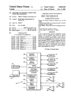
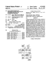
IllllllllllllllllllllllIlIIllllllllllIIIIIlllllllllllllllllllllllllllllllll
US005293494A
United States Patent [191
[11] Patent Number:
Saito et a1.
[45]
[54] PERSONAL COMPUTER FOR SETTING, IN
4,974,151 11/1990
NORMAL/REVERSE DISPLAY,
OTHER PUBLICATIONS
T1200 Portable Personal Computer User’s Manua
1-1987, pp. 4-18, 4-19 Toshiba.
T1600 Portable Personal Computer User’s Manual,
First Ed., Sep. 1988, pp. 4-30 Toshiba.
T3100e Portable Personal Computer Reference Man
[75] Inventors: Toshimitsu S‘aito, Fuchu; Junko
Konno, Oome, both of Japan
[73] Assignee: Kabushiki Kaisha Toshiba, Kawasaki,
Japan
[21] App1.No.: 29,963
ual, First Ed., Sep. 1988, Figs. 3A-3D, p. 3/9, Toshiba.
Jakopin, version 3.07, Aug. 1988 Computertechnik
Kieckbusch GmbI-I “Steve”.
‘Primary Examiner-Robert L. Richardson
Mar. 9, 1993
Related US. Application Data
Attorney, Agent, or Firm—0blon, Spivak, McClelland,
Maier & Neustadt
Continuation of Ser. No. 541,948, Jun. 22, 1990, aban
doned.
[57]
Foreign Application Priority Data
Jun. 23, 1989 [JP]
Jun. 23, 1989 [JP]
performed to select a display mode, either a normal-dis
play mode or a reverse-display mode, and also to select
Japan .................................. .. 1-62233
Japan ................................ .. l-l62232
Int. Cl.5 ....................... .. G06F 13/00; G06F 1/26
US. Cl. .................................. .. 395/275; 395/106;
[53]
Field of Search ............. .. 395/ 109, 156, 275, 700,
one of the external devices such as a printer and an
external floppy disk drive. Also, a display auto-off mode
and a display auto-off period are set during the setup
processing. A period is measured during which no data
is input from a keyboard. When the measured time
395/156; 395/700
395/325
value exceeds the display auto-off period, the supple
References Cited
U.S. PATENT DOCUMENTS
4,604,690
4,733,351
8/1986
3/1988
ABSTRACT
A personal computer, wherein a setup processing is
[51]
[52]
[56]
364/483
..... .. 364/200
FUNCTION
[30]
Advani =1 a1. .................... .. 364/200
4,979,107
4,980,836
5,014,193 12/1990
5/1991 Advani
Carter
Garneretct
eta1.
a1.
CONNECTION OF AN EXTERNAL DEVICE,
AND AN AUTOMATIC DISPLAY OFF
[63]
Mar. 8, 1994
.. 364/200
A SOFTWARE SETUP OPERATION
[22] Filed:
Date of Patent:
5,293,494
ment of power to the back light is stopped automati
cally.
Crabtree et a1. .................. .. 395/700
Peirent .............................. .. 395/144
H
,
17 Claims, 17 Drawing Sheets
,._.'_‘-:____,
IiCPU
,
HDC lmmnlas'ili
L. _
_
_
_
_
_
_
_
_
_
__.1
12
@
‘32
--
FDC
1
VBK
IEXTERNAL FDDI
‘
24
‘4
CONT
L """" "155':
L _ _ _ _ _ _ _ _ __.l
’
22
YRS-I256“:
,5
23
LWPLJEE’U'
m
16
l
35
msP
LCD
v
--
n
__
@
J9
RAM
37
VRAM
KANJI
_\—]Z\_____TJ
CRT 1
ROM
~26
ROM
pS_|F
i-(VBK
is
27
3§
29
11.2
RAM
aAcKuP
“x18
__
'
396
[3:1
‘E11
"‘
“>- ADAPTER “>- PEOWERFFLY
I‘.
.
3'»
r-'---'-|
DICTIONARY
VBK exrsnoso
VBK
:
as
|_ ____ __,-'____,
13
AC
—-va1<
40
US. Patent
Mar. 8, 1994
Sheet 3 of 17
5,293,494
I START I SETUP PROCESSING
TURN OFF SYSTEM REBOOT FLAG
~SI
S2
NO
ALTERAT ION
OF DISPLAY AUTO-OFF
'?
NO
YES
SET PERMISSION/INHIBITION OF
DISPLAY AUTO-OFF MODE
~53
SET DISPLAY AUTO-OFF TIME
~S4
ALTERATION
OF DISPLAY NORMAL/
REVERSE ?
YES
SET NORMAL/REVERSE DISPLAY FLAG ~S6
S7
PRESENCE
OF ALTERATION OF EXTERNAL
UNIT CONNECTION
YES
SET CONNECTION STATUS OF
EXTERNAL UNIT
~88
TURN ON SYSTEM REBOOT FLAG
~S9
FIG. 3A
(‘9
US. Patent
Mar. 8, 1994
Sheet 4 of 17
OTHER SETUP PROCESSING
5,293,494
~S1O
lS
SYSTEM REBOOT
REQUIRED ?
YES
REBOOT
SYSTEM
END
FIG.
3B
~S42
US. Patent
Mar. 8, 1994
Sheet 5 of 17
5,293,494
m ; >2_m.<|Em
0n.E2PO3|D><bm
m0
~
5
_
muzw m
v
A
Zm3._ m
Nu
,
mu
,
US. Patent
Mar. 8, 1994
Sheet 6 of 17
5,293,494
DISPLAY NORMAL / REVERSE
CONTROL PROCESSING (S6)
Di
NORMAL DISPLAY ?
YES
DP
NORMAL DISPLAY
REVERSE DISPLAY
J
END
FIG.
5
US. Patent
Mar. 8, 1994
Sheet 8 of 17
( START )
5,293,494
POWER-OFF ROUTINE
/ C
\T
A1
‘
|s
ATTERY VOLTAGE
NO
NORMAL?
NONCONNECTION I
YES
A3
|
ABNORMAL DISPLAY
(FUCKER LED)
AC ADAPTER
*
CONNECTED‘?
l
A2
CONNECTION
,8
A4
AOAPTER P
_
ABNORMAL
OuRCE NORMAL
A?
‘NORMAL
TuRN ON LED
TURN ON LED
YES
DISPLAIY FRAM
CLOsEO ?
NO
No
IS
POWEORNSWITCH
?
YES
DECREASE CHARGE
UNIT VOLTAGE BY
I
ONE STEP
A44
CTR—-—CTR + 4
INCREASE CHARGE
UNIT VOLTAGE BY
ONE STEP
IAu
TO POWER ON ROUTINE
F l
7
US. Patent
Mar. 8, 1994
START
Sheet 9 of 17
POWER — ON
I
5,293,494
ROUTINE
<5]
8'
IS
No
UNCEO)I(\I1NEEI\CIZSIBEDBI 0%”‘2,
PREPARATION'PCOMPLETED
5525
T
ABNORMAL DISPLAY
( F LICKER LED)
POWER ON PROCESSING
POWER OFF
PROCESSING
ARE
RESPECT l VE
OUTPUT VOLTAGES
B 26
NORMAL ‘P
w
9% RELEASE
85
SYSTEM RESET
TO POWER-OFF
ROUTINE
ARE
RESPECTIVE
OUTPUT VOLTAGES
NORMAL ?
YES
ABSENCE
_ RESENCE
B6
F RECEPTION COMMAND
FROM M7AIN CPU
PRESENCE
B7
POWER-OFF
COMMAND ?
B8
BACK LIGHT
NO
ON / OFF ‘COMMAND
ri340
TURN OFF BACK LIGHT
gggggsg?gmm
_I
FIG. 8A
(9
US. Patent
Mar. 8, 1994
Sheet 10 of 17
IS
HARGE / DI SCHARGE
CURRENT OF BATTERY
ORMAL'?
NO
'
5,293,494
BH
B12
DISCHARGE
CURRENT ‘ABNORMAL
REGULATE VOLTAGE OF
N843
CHARGE UNIT
BATTERY IN
LOW-BATTERY STATE
YES
B45
INOPERABLE
VOLTAGE ?
NO
3'6
TURN ON LOW-BATTERY LED
817
UNCONNECTED
‘
Is
AC ADAPTER
UNCONNECTED/NORMAL
/ABNORMAL ?
ABNORMAL
_'§>
ORMAL
DC
BB7
m - LED
S
RESET SWITCH
N548
B 19
DEPRESSED ?
RESET
Q57
FIG. 8B
US. Patent
Mar. 8, 1994
Sheet 11 of 17
IS
DISPLAY CLOSED
5,293,494
YES
'7
POWER SWITCH
ACTUATED ?
82(3
'
CTR -—- CTR + 1
B24
CTR = M ?
NO
E>_______ YES
(E)
TRANSMIT MAIN CPU COMMAND
\
B20
RECEPTION
OF POWER-OFF
COMMAND?
FIG. 8C
828
US. Patent
Mar. 8, 1994
Sheet 12 of 17
FIG. 9A
5,293,494
US. Patent
Mar. 8, 1994
Sheet 13 of 17
5,293,494
US. Patent
Mar. 8, 1994
Sheet 14 of 17
5,293,494
[ [SYSTEM sETuP ] ] ----------- - - VERSION x. xx
I. HARD RAM SIZE
= 0 KB
2 . STANDARD MEMORY PORT ADDRESS = 258 H
3 . EXTENDING MEMORY PORT ADDRESS= 208H
4. RESUME FUNCTION
= DISABLE
5. PRT-A--B
=
PRT
=
DISABLE
6.REVERSE
DISPLAY
7. AUTO DISPLAY-OFF TIME
= DISABLE
8. DISPLAY MODE
=
CGA(80* 25)
=
COM I
I0. INCORPORATED MODEM
=
ENABLE
II. INCORPORATED MODEM POWER
=
OFF
I2. LOW-BATTERY SPEAKER
=
ENABLE
I3. SYSTEM SPEAKER SOUND
=
ENABLE
I4. PRINTER PORT TYPE
= OUTPUT MODE
9. INCORPORATED RS-232C
PORT
SOUND
ENTER] ITEM CHANGE [-] CONTENT CHANGE
[ FI ] COMPLETION [F5] STANDARD SETTING
[FIO] WRITE CHANGED CONTENTS
FIG. IO
US. Patent
~
24
US
A
LA
0Awm
T
Sheet 15 of 17
Mar. 8, 1994
>B
L.-.
M‘L 3mkw4am
50
DD
BA“
>\2
I.A
B
%mwko4um
.YO. . . ~"2.",
a
+
.
8
mm2AB
YLMT
L
M
) 37
a
.._.. PSLE
AA0 D/CARD3D
Pm Y. .
FIG. 11
US. Patent
Mar. 8, 1994
Sheet 16 of 17
5,293,494
[[SYSTEM $ETUF’]] ----------- -- vERSION x.xx
I. HARD
RAM SIZE
= 0 KB
2. STANDARD MEMORY PORT ADDRESS = 258 H
S. EXTENDING MEMORY PORT ADDRESS = 208 H
4. RESUME FUNCTION
= DISABLE
5. PRT —A-B
= PRT
G. REVERSE
7. AUTO
DISPLAY
= DISABLE
DISPLAY-OFF
8. DISPLAY
= ENABLE
MODE
= CGA(80*25)
9. INCORPORATED Rs-232C PORT
= COM I
I0. INCORPORATED MODEM
= ENABLE
II. INCORPORATED MODEM POwER
= OFF
I2. Low-BATTERY SPEAKER SOuND
= ENABLE
I3. SYSTEM
= ENABLE
SPEAKER SOuND
I4. PRINTER PORT TYPE
= OUTPUT MODE
[1 I ENTER] ITEM cI-IANGE [-1 CONTENT CHANGE
[PI ]COMPLETION [F5] STANDARD SETTING
[FIO] wRITE CI-IANGED CONTENTS
FIG. 12
U.S. Patent
Mar. 8, 1994
Sheet 17 of 17
5,293,494
113.1%???1 £118.:
mMwawm."n
w
n
m
“=5ESEE538
"| IL.1
u
u
m5.16528
__Kim
_
-
o
_..JlIIl|Il
_m5az:es3.
.0_m
1
5,293,494
ther the normal-display mode 0 the reverse-display
mode in the setup processing, and means for controlling
the normal display mode or the reverse display mode
set by the setting means.
NORMAL/REVERSE DISPLAY, CONNECTION OF
According to a second aspect of the invention, there
AN EXTERNAL DEVICE, AND AN AUTOMATIC 5
is provided a personal computer capable of performing
DISPLAY OFF FUNCTION
a setup processing for setting a system environment,
said computer comprising: means for setting a connec
"This application is a continuation of application Ser.
tion status of a unit connected to said computer in the
No. 07/541,948, ?led on Jun. 22, 1990, now abandoned.
10 setup processing; and means for specifying the system
PERSONAL COMPUTER FOR SETTING, IN A
SOFTWARE SETUP OPERATION
BACKGROUND OF THE INVENTION
1. Field of the Invention
The present invention relates to a personal computer
environment based on data from said setting means.
According to a third aspect of this invention, there is
provided a method of setting a normal-display mode or
which is portable and is capable of being driven by a
reverse-display mode in a personal computer which is
built-in battery, and more particularly to a personal
provided with a display means having normal and re
verse display modes and which performs a setup pro
computer having a setup processing function, which has
means for selecting and setting normal/reverse display
cessing for setting a system environment, said method
comprising the steps of: displaying, on a display unit a
and external units such as a ?oppy disk drive, a printer
and the like, and which is adapted for an arrangement
menu screen for selecting the normal-display mode or
where a display section is provided having a speci?c 20 the reverse display mode in the setup processing; and
selectively setting the normal-display mode and the
function section such as a back light which necessitates
reverse-display mode on the select menu screen.
a relatively large power.
According to a fourth aspect of this invention, there
2. Description of the Related Art
is provided a personal computer provided with a dis
In recent years, a variety of portable, internal-bat
tery-operable personal computers have been developed. 25 play means and an input means, and capable of perform
ing a setup processing for setting a system environment,
Each of these computers has means for selecting and
said computer comprising: means for setting a display
setting a normal/reverse display mode and external
auto-off mode during the setup processing; means for
devices connected to the computer, from a view point
of operability and functionality. In a prior art, the selec
ting/setting means is realized by manual switches which
measuring a period of time during which said input
means remains not operated after the display auto-off
are arranged on the main body of the computer and
mode has been set; means for disabling a speci?c func
positioned such that the operator can easily operate
tional operation of said display means when the period
them. For this reason, a conventional personal com
of time measured by said time measuring means exceeds
a predetermined value; and means for enabling the spe
ci?c functional operation of said display means when
puter is provided with many switches, resulting in com
plicated operations and hardware arrangement.
Furthermore, this type of personal computer must be
35
said input means is operated while the speci?c func
operated not only with an AC adapter but by a built-in
battery in order to ensure the usability irrespective of a
place where it is used.
In order to satisfy such demand, a back-lit liquid
crystal display (LCD) may be used. However, as is well
tional operation is disabled.
ble and built-in battery operable personal computer
menu screen, including a setting of the display auto-off
According to a ?fth aspect of the present invention,
there is provided a personal computer having a display
means and an input means, and capable of performing a
setup processing for setting a system environment, said
computer comprising: means for setting a display auto
known in the art, a back-lit LCD consumes a relatively
off mode and an auto-off period in the setup processing;
large amount of power. Therefore, it is difficult to use
means for measuring a period of time during which said
the personal computer for a long time with only the use
of a normal built-in battery. On the contrary, if a large 45 input means remains not operated after the display auto
off mode has been set; means for disabling speci?c func
capacity built-in battery is used in order to satisfy this
tional operation of said display means when the period
requirement, a weight of the built-in battery is in
of time measured by the time measuring means exceeds
creased, resulting in a decreased convenience of porta
the auto-off period; and means for enabling the speci?c
bility.
functional operation of said display means when said
SUMMARY OF THE INVENTION
input means is operated while the speci?c functional
operation is disabled.
An object of the present invention is to provide a
According to a sixth aspect of this invention, there is
personal computer which excludes a switch for setting
provided a method of automatically disabling a display
a normal/reverse display, a switch for setting external
units and the like, and simpli?es the operability and the 55 of a screen for a personal computer having a display
means and an input device, and capable of performing a
hardware arrangement thereof by realizing the setting
setup processing for setting a system environment, said
function in a set up processing.
method comprising the steps of: a) displaying a setup
Another object of the invention is to provide a porta
mode, on said display means; b) setting the display auto
off mode; 0) measuring a period of time for which said
input means is not actuated after the display auto-off
with a speci?c function section such as a back light
mode has been set; d) disabling a speci?c functional
which consumes relatively large power.
operation of said display means when the period of time
According to a ?rst aspect of the invention, there is
provided a personal computer having display modes of 65 measured exceeds a predetermined value; and e) detect
ing an input from said input means, while the speci?c
a normal-display and a reverse-display and performing a
function is disabled and enabling the speci?c functional
setup processing for setting a system environment, said
operation of said display means.
computer comprising: means for selectively setting ei
which can extremely reduce, without decreasing the
operability, a power dissipation of a display provided
3
5,293,494
4
According to a seventh aspect of this invention, there
DETAILED DESCRIPTION OF THE
is provided a method of automatically disabling a dis
PREFERRED EMBODIMENTS
play of a screen for a personal computer having a dis
FIG. 1 is a system diagram of an embodiment of a
play means and an input means, and capable of perform
ing a setup processing for setting a system environment, 5 personal computer of the present invention, and FIG. 2
is a block diagram of a power~supply circuit 30 in
said method comprising the steps of: a) displaying a
coporated in the computer in FIG. 1.
setup menu screen, including a setting of the display
auto-off mode, on said display means; b) setting the
display auto-off mode and an auto display-off period; c)
measuring a period of time for which said input means
is not actuated after the display auto-off mode has been
set; d) disabling a speci?c functional operation of said
display means when the period of time measured ex
ceeds the auto display-off period; and e) detecting an
input from said input means, while the speci?c function
is disabled and enabling the speci?c fucntional opera
tion of the display means in response to the input.
Additional objects and advantages of the invention
will be set forth in the description which follows, and in
part will be obvious from the description, or may be
learned by practice of the invention. The objects and
advantages of the invention may be realized and ob
tained by means of the instrumentalities and combina
tions particularly pointed out in the appended claims.
BRIEF DESCRIPTION OF THE DRAWINGS
The accompanying drawings, which are incorpo
rated in and constitute a part of the speci?cation, illus
trate presently preferred embodiments of the invention,
and together with the general description given above
and the detailed description of the preferred embodi
ments given below, serve to explain the principles of the
invention.
As is shown in FIG. 1, the computer comprises a
system bus 10 and components 11 to 17 connected to the
bus 10. These components are: a main CPU (Central
Processing Unit) 11, a ROM (Read Only Memory) 12, a
RAM (Random Access Memory) 13, a DMAC (Direct
Memory Access Controller) 14, a PIC (Programmable
Interrupt Controller) 15, a PIT (Programmable Interval
Timer) 16, and a RTC (Real Time Clock) 17.
The main CPU (Central Processing Unit) 11 controls
an entirety of the system, and executes the various rou
tines represented by the ?ow charts shown in FIGS. 3A
and 3B, 4 to 7, and 8A through 8C. The main CPU 11
serves as a host CPU to the power control CPU incor
porated in the power-supply circuit 30 to be described
later.
The ROM 12 stores a basic input and output program
(BIOS). The main CPU 11 executes the BIOS when the
25 power switch of the computer is turned on to read the
setup data stored in a speci?c area of the RAM 13 (or
register) to determine the system environment, to fur
ther read a boot block from a floppy disk drive (FDD)
32, and to load an disk operating system (DOS) pro
gram stored in the FDD 32 into the RAM 13. The
RAM 13 stores the DOS (Disk Operating System) pro
gram, the system programs shown in FIGS. 3A to BC,
application programs, and various data including setup
data to be described later. Backup power VBK is sup
FIG. 1 is a system diagram showing an embodiment 35 plied to the RAM 13 from the power-supply circuit 30.
of a personal computer according to the present inven
Hence, the data stored in the RAM 13 is not vanished
tion;
even if the power switch of the computer is turned off.
FIG. 2 is a block diagram showing the power-supply
The DMAC 14 performs a direct memory access
incorporated in the computer shown in FIG. 1;
control. The PIC 15 can be set by a program. The PIT
FIGS. 3A and 3B illustrate a ?ow chart representing 40 16 can be set by a program and supplies an interrupt
the setup processing routine for the personal computer
signal to the main CPU 11 under control of the PIC 15
shown in FIG. 1;
when its count reaches a value set by a program. In
FIG. 4 is a flow chart explaining the auto display-off
response to the interrupt signal, the main CPU 11 exe
processing routine for the computer shown in FIG. 1;
cutes vector interrupt processing routine to thereby
FIG. 5 is a flow chart showing the normal/reverse 45 execute a routine of determining whether or not data
display processing routine for the computer shown in
has been input from a keyboard 36 within a predeter
FIG. 1;
mined time. If no data has been input within the prede
FIG. 6 is a ?ow chart showing the unit-connection
termined time, the main CPU 11 will execute auto dis
status processing routine for the computer shown in
play-off routine which will later be described in detail.
FIG. 1;
50 The RTC 17 is a timer module which has a dedicated
FIG. 7 is a flow chart showing the power-off process
built-in battery (not shown) and measures time; its out
ing routine executed by the power control CPU 306
put represents the present time.
incorporated in the computer shown in FIG. 1;
As is shown in FIG. 1, the personal computer further
FIGS. 8A through 8C illustrate a flow chart showing
comprises an extended RAM 18, a backup RAM 19, a
the power-on processing routine executed by the power 55 hard disk pack 20, a floppy disc controller (FDC) 20F,
control CPU 306 used in the computer illustrated in
a printer controller (PRT-CONT) 21, an I/O interface
22, a keyboard controller 23, a display controller 24, a
FIGS. 1 and 2;
FIGS. 9A and 9B are perspective views showing an
video RAM 25, a Kanji ROM 26, a dictionary ROM 27,
and a power-supply interface 28—all connected to the
embodiment of the personal computer;
FIG. 10 is a diagram showing an example of the setup
system bus 10.
The extended RAM 18 is a large-capacity memory
screen in the embodiment of the present invention;
FIG. 11 is a block diagram illustrating an arrange
ment of a normal/reverse display switching circuit in
removably inserted in the card slot formed in one side of
corporated in the computer;
power VBK is supplied to the extended RAM 18. The
the main body of the personal computer, and the backup
FIG. 12 is a diagram showing a modi?cation of the 65 backup RAM 19 is also supplied with the backup power
VBK and keeps storing the data required to perform a
setup screen shown in FIG. 10; and
resume function. The hard disk pack 20 is removably set
FIG. 13 is a block diagram showing a modi?cation of
in a dedicated housing made in one side of the main
the embodiment of the present invention.