1
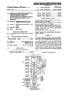
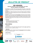
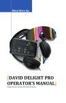
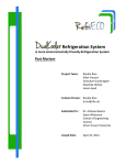
April 17, 2014 Dr. Andrew Rawicz School of Engineering Science Simon Fraser University Burnaby, BritishColumbia V5A 1S6 Re: Post Mortem - Solar Powered Battery Charger for an Offshore Hydrophone Dear Dr. Rawicz, Throughout the Spring 2014 semester, AquaSol Solutions has been collaborating with the Department of Fisheries and Oceans (DFO) to develop a stand-alone solar system for supplying power to an offshore hydrophone. This hydrophone will be used by the DFO to monitor killer whale migration patterns. The following document contains the post-mortem for AquaSol Solutions' engineering Capstone project. The post-mortem presents a general overview of the system before discussing the logistics of bringing the project to completion. These logistics include final system costs, materials used, and a timeline of the Capstone project. The group dynamics and workload distribution among team members are discussed, as well as technical challenges encountered throughout the design process. Finally, the document is concluded with every team member’s reflections on their individual Capstone experience. This document closes the book on what we feel was an educational and productive Capstone project experience. Should you have any questions regarding information in this document, please do not hesitate to get in touch. Sincerely, AquaSol Solutions Bharat Advani Marty Gradowski Aiste Guden Michael Lew David Stevens AquaSol Solutions Page ii Solar Powered Battery Charger for an Offshore Hydrophone Post Mortem Project Members: Bharat Advani Marty Gradowski Aiste Guden Michael Lew David Stevens Contact Person: David Stevens [email protected] Submitted to: Dr. Andrew Rawicz – ENSC 440W Steve Whitmore – ENSC 305W School of Engineering Science Simon Fraser University Issued Date: April 17, 2014 AquaSol Solutions Page iii Table of Contents Glossary ................................................................................................................................................. 3 1. Introduction .................................................................................................................................. 4 2. Project Overview ...........................................................................................................................4 3. 2.1 Materials ................................................................................................................................6 2.2 Costs ....................................................................................................................................... 7 2.3 Schedule .................................................................................................................................8 Technical Challenges .................................................................................................................. 10 3.1 System Interfacing .............................................................................................................. 10 3.2 Software ................................................................................................................................11 3.3 Hardware ............................................................................................................................. 13 4. Group Dynamics ......................................................................................................................... 13 5. Workload Distribution................................................................................................................ 14 6. 7. 5.1 Technical Tasks ................................................................................................................... 14 5.2 Administrative and Support Tasks..................................................................................... 15 Individual Reflections ................................................................................................................. 15 6.1 Bharat Advani ...................................................................................................................... 15 6.2 Marty Gradowski ................................................................................................................. 15 6.3 Aiste Guden .......................................................................................................................... 18 6.4 Michael Lew ........................................................................................................................ 20 6.5 David Stevens ...................................................................................................................... 21 Conclusion ...................................................................................................................................22 References ...........................................................................................................................................23 Appendix A: Meeting Agenda ............................................................................................................24 Appendix B: Meeting Minutes ........................................................................................................... 27 AquaSol Solutions Page 1 List of Figures Figure 1: High-level overview of components and their connections ...............................................6 Figure 2: Final timeline of the project............................................................................................... 10 List of Tables Table 1: Materials used in system components ..................................................................................6 Table 2: Final cost breakdown ............................................................................................................. 7 Table 3: Technical workload distribution ......................................................................................... 14 Table 4: Administrative workload distribution ................................................................................ 15 AquaSol Solutions Page 2 GLOSSARY BMS Battery Management System CAN Controlled Area Network CEC Canadian Electric Code CSA Canadian Standards Association DC Direct Current DFO Department of Fisheries and Oceans GPIO General Purpose Input/Output GSM Global System for Mobile Communications IC Integrated Circuit IO Input/Output ISM Industrial, Scientific, and Medical LVD Low Voltage Disconnect MCU Microcontroller Unit MPP Maximum Power Point MPPT Maximum Power Point Tracking OCP Over Current Protection OCPD Over Current Protection Device OSI Open Systems Interconnection PCB Printed Circuit Board PMU Power Management System RH Relative Humidity SOC State of Charge STC Standard Test Conditions AquaSol Solutions Page 3 1. INTRODUCTION The Department of Fisheries and Oceans (DFO) has deployed several land-based hydrophones for monitoring the migration patterns of British Columbia’s endangered resident killer whales. The DFO has recently expanded on this project with the introduction of offshore hydrophones. With no conventional power source accessible in this remote location, AquaSol Solutions has been asked to design a stand-alone, solar-powered system to autonomously run the hydrophone and monitor the state of the batteries. Throughout the Spring 2014 semester, AquaSol Solutions has built and demonstrated a mockup of the designed solar powered battery charger. This document describes the current state of the project, along with its intended course for future development. The final project costs, materials used, and comparison with the initially proposed schedule [1] are discussed, proceeding a general project overview. This document also outlines the technical challenges encountered by AquaSol Solutions throughout the design process. Finally, a discussion on group dynamics, workload distribution, and the team members’ personal reflections on their Capstone project experiences are presented. 2. PROJECT OVERVIEW The purpose of the project was to design a stand-alone solar powered system capable of autonomously supplying power to an offshore hydrophone and monitoring the state of the batteries. The Charging Module harvests solar energy and protects the Battery Pack (energy storage device for the system) from overcharge. The Central Module is where all of the interconnections between the batteries, power management unit, and peripherals take place. These peripherals (External Devices) include the hydrophone and ISM (Industrial, Scientific, and Medical) unit, which is used for transmitting hydrophone data to a base station. Finally, a remote application receives the data onto a server and displays the information onto a web AquaSol Solutions Page 4 application. A high-level functional diagram of the system is shown in Figure 1 [2]: AquaSol Solutions Page 5 Figure 1: High-level overview of components and their connections 2.1 MATERIALS Many components went into building a mockup of the solar powered battery charger. As per requirement [R83-B] from the Functional Specifications [3], AquaSol Solutions ensured that all electrical components were RoHS compliant. No such hazardous materials were used in the production of the system components used for the mockup. The main materials used in the system components are outlined in Table 1: Table 1: Materials used in system components System Component Materials Lithium batteries Lithium iron phosphate, plastic, aluminum Monocrystalline solar panels Aluminum, silicon, plastic AquaSol Solutions Page 6 Charge controller Plastic, copper, silicon, aluminum DC circuit breakers, relays, wires Plastic, copper, aluminum DC-DC converter Aluminum, silicon Interfacing connectors Plastic, copper, aluminum Battery management system (BMS) Plastic, copper, aluminum, silicon SubConn underwater cable Plastic, copper, aluminum Acryllic board Polyacrylonitrile Humidity sensor Aluminum, silicon, plastic Microcontroller and development board Plastic, copper, aluminum, silicon, gold Electronic components Aluminum, silicon, plastic PCBs Plastic, copper, aluminum, silicon Solder Tin, traces of other metals 2.2 COSTS AquaSol Solutions went significantly over budget on the Capstone project. The solar powered battery charger will be placed in a harsh marine environment, where high quality components need to be used. All of the parts purchased ended up being top-of-the-line, causing the actual costs for the system mockup to run well over the estimated costs outlined in the project proposal [1]. A final comparison between the estimated and actual costs is presented in Table 2: Table 2: Final cost breakdown Part Covered By Estimated Cost Actual Cost Solar Panels DFO ~$400 ~$400 Charge Controller DFO $499.99 $299.40 DC Circuit Breakers DFO $44.25 $26.55 DFO ~$2500 ~$2500 Solid State Relay TBF $59.38 $59.38 MCU and Dev Board TBF $185 $199 Batteries, Battery Management System (BMS), and Contactor AquaSol Solutions Page 7 Backup Battery for MCU TBF $24.64 $24.64 Hardware Eval Boards Linear Tech $225 FREE PCB manufacturing TBF $300 $463.00 PCB and Breadboard ESSEF $100 $739.85 TBF - $193.67 ~$4338 ~$4905 Components Misc (RP Electronics, MRO, Sparkfun) Total The team vastly underestimated the cost of the micro-electronic components needed for the PCB and for prototyping. This was due to evolving circuit requirements as the term progressed. Increased circuit requirements demanded increased amounts of circuit components, and consequently resulting in increased cost from our original projection. With new circuitry demands, the team first had to buy components to test out on a breadboard before committing them to the PCB, which added additional overhead costs. On the other hand, the team received an educational discount from Midnite Solar on the charge controller and DC circuit breakers. The team also received free evaluation boards from Linear Tech. In the end, the actual mockup costs worked out to about 114% of the estimated costs. 2.3 SCHEDULE Research and selection of the system components took longer than initially outlined in the project proposal [1]. AquaSol Solutions underestimated the length of time required to get ahold of representatives from various companies and get the answers required to move forward in the project. It is remarkable how much faster questions get answered if you are working with the government, rather than representing a team of engineering students from university. The last minute addition of a low voltage disconnect (LVD) circuit and a Controlled Area Network (CAN) transceiver pushed back the design of the printed circuit board (PCB). On the software side, AquaSol Solutions Page 8 programming the I2C drivers for the humidity sensor took longer than expected, as did the CANbus communication. Luckily, AquaSol Solutions allotted a conservative amount of time for hardware and software integration, which allowed the team to catch up in time for the final project demo. The final timeline of AquaSol Solutions’ Capstone project is shown in Figure 2: AquaSol Solutions Page 9 Figure 2: Final timeline of the project 3. TECHNICAL CHALLENGES Team members working on hardware, software, and system interfacing experienced several technical challenges throughout the semester. This section presents a breakdown of these challenges. 3.1 SYSTEM INTERFACING A significant amount of time was spent planning how to interface all the different systems together and because of that, there were few technical challenges that presented themselves during the final hardware system integration phase. Notably the most obvious oversight was opting to get connectors that did not have the same number of pins as the matching system, thinking that the unused or seemingly optional connections would not be required. This was a mistake and required hardwiring some connections together that should have been AquaSol Solutions Page 10 detachable by original design. Additionally as the interface module came together it was discovered that there were additional connections required that were not known during the part selection phase. In the future all connectors that are to be used should be ensured to have the correct number of pins for the matching system and optionally some connectors should allow for additional connections when the exact number is unknown. A late discovered technical issue arose from the cable/connector combination that was used to connect the batteries to the interface module. The cable and connector which as a pair were provided by the same company, did not have the same coloring to pin out scheme which resulted in an initial incorrect wiring configuration which posed issues with successfully communications between the battery and BMS. A secondary issue was identified that when connected together two pairs of pins would swap pin outs, which indicated shorts were occurring within the sealed cable or connector. 3.2 SOFTWARE A number of software challenges were encountered during development. First, developing on a board that did not have the capacity to hold a monolithic operating system was a challenge. A full operating system (such as Linux), in addition to scheduling, offers the benefits of memory management, simpler debugging, and driver abstractions for ease of use. In our case, we put FreeRTOS, a microkernel on the MCU, that only offered basic task scheduling and priority management. Any additional driver communication and interrupt handling had to be implemented by the developers. The drawbacks of this were that it made development and debugging far more complicated. If we had chosen an MCU that could hold a monolithic kernel, very likely the performance would have decreased and the system would have run slower with lower available memory. For this type of application, the group decided that it was not an appropriate fit. However, for fast prototyping, it would have been a useful option to consider, with the intent of switching to a more suitable firmware platform later on, if time permitted. The software group also had to implement proper CAN communication between the PMU and BMS. The BMS sends periodic CAN messages regarding battery status, temperature, AquaSol Solutions Page 11 voltage, and other diagnostics. One of the challenges we encountered was getting basic CAN communication to work when connecting the PMU to the BMS. It was difficult to isolate all the problems that were occurring and to determine what issues resided in software and which were in hardware. Thus, we chose to isolate the PMU and connected its CAN pins to two transceivers on a breadboard in order to establish a base level of functionality. Once that was working, we reconnected the PMU to the BMS to see if it was receiving messages. When we determined it wasn’t, we continued to debug the hardware setup on the PCB and the connections to the BMS in order to find the issues. One of the major lessons we learned through this project was the necessity of isolating each functional component and incrementally establishing a working system before integrating it further. Ethernet communication, which is used to connect the microcontroller to the web application via the wireless transmitter, was a big challenge and was not fully functional at demo time. The team did not start work on Ethernet as early as they could have. Part of the reason for the late start the team’s belief that Ethernet communication could be achieved the same way as communication via other peripherals. However, unlike I2C and, to a certain extent, CAN, communication via Ethernet is significantly more complicated than finding the right sequence of API calls to make. As the team later found out, this is because communication over Ethernet covers many more OSI model layers than I2C and CAN. Technically speaking, Ethernet covers only the physical and link layers – the same as CAN. However, since the Ethernet connection is being used to communicate with a web server, the Ethernet driver also needs to handle TCP/IP and HTTP. Both members of the firmware team were mostly unfamiliar with networking protocols, and this was a major source of challenges. Furthermore, the standard way of implementing web clients in microcontrollers revolves around the use of event and interrupt handlers, as well as callback functions. This design philosophy made it difficult to follow the logic of the code, and even more difficult to debug. AquaSol Solutions Page 12 3.3 HARDWARE It was difficult to properly simulate a battery using the included netlists in LT SPICE. A large capacitor had to be used as a model to simulate the functionality of the backup battery charging circuit, source select circuit, and buck converter. The low voltage disconnect (LVD) had to be simulated separately, as a capacitor model for a battery was not suitable. In the design of the LVD circuit, the drain and source connections of the NMOS switch (used to disconnect the backup battery in a low voltage condition) were reversed. The circuit still functioned properly when the main 24V battery pack was connected, but started to malfunction when the main battery pack was disconnected. This was discovered after the PCB was manufactured: extra jumper wires and solder had to be used to alleviate this problem. With regards to the LVD circuit, another poor design was not including hysteresis on the comparator. This caused the logic output level of the comparator to oscillate near the threshold. This was remedied by soldering extra resistors to the PCB to provide the initially overlooked hysteresis. AquaSol Solutions’ PCB designer noticed that a bug in the PCB layout software (Eagle) caused one of the voltage rails to be excluded from the Gerber file. This caused the PCB manufacturing company to exclude this voltage rail from fabrication, so an extra jumper wire needed to be soldered to the PCB. Difficulties were also found in soldering some of the components with particularly small pitches between pins as well as thermal pads. 4. GROUP DYNAMICS The team members of AquasSol Solutions are highly motivated students, where everyone felt the desire to contribute as much as they can to the project. Therefore, a top-down organization structure seemed unnecessary. The team opted for a bottom-up structure, and it has proven to be very effective. Team members would take the lead in situations where they felt they were most qualified, and stepped back in situations where others could make a better judgment call. This worked well, since the team has a very diverse skillset. Throughout the documentation process, the team would meet in the library study rooms to establish who was responsible for which sections of a given document. This decision was based AquaSol Solutions Page 13 on team member expertise and availability. Shortly before the due date, the team would meet in an ASB conference room, order pizza, and perform a group editing session. This way, the group was in agreement on the entire document before submission. 5. WORKLOAD DISTRIBUTION There was no shortage of work throughout the design process of the solar powered battery charger. At any given moment, when one team member finished his or her respective technical task ahead of schedule, there were always ways of contributing to the team with administrative and support roles. This section provides a breakdown of the workload distribution among AquaSol Solutions’ team members. 5.1 TECHNICAL TASKS Completion of the solar powered battery charger mockup involved technical tasks associated with hardware, software, and system integration. All team members contributed to these tasks. The technical workload distribution among team members is outlined in Table 3: Table 3: Technical workload distribution Task Bharat Marty Aiste PCB layout and soldering Michael X Circuit design X Photovoltaic system sizing XX CANbus communications XX X XX I2C communications XX Ethernet communications X X Software engineering X X X Web server Web page David XX X X Connections, wiring, and XX system integration Microcontroller selection Hardware testing AquaSol Solutions X X X X X Page 14 Software testing X X X 5.2 ADMINISTRATIVE AND SUPPORT TASKS The team members took many administrative and supporting roles upon themselves to facilitate the implementation of the technical tasks. The administrative workload distribution among team members is outlined in Table 4: Table 4: Administrative workload distribution Task Bharat Contact and liaison with project Marty Aiste Michael David X X X X collaborators Team liaison with Mr. Steve X Whitmore Research X X X X X Documentation X X X X X Document formatting XX Booking meeting rooms Meeting minutes Parts Sourcing Financial bookkeeping X X X X X X X XX X 6. INDIVIDUAL REFLECTIONS This section contains the personal reflections of the AquaSol Solutions team members on their overall Capstone project experience. 6.1 BHARAT ADVANI As one of the more software-oriented members of the team along with Aiste, my primary tasks were writing the humidity sensor driver (via I2C) and getting the Ethernet communication working and integrated with FreeRTOS. My sole and limited contribution to hardware was helping Martin test and debug the LVD circuit for the backup battery. AquaSol Solutions Page 15 On the software side, I learned more about firmware programming in general. Specifically, I learned bits and pieces of serial communication (particularly I2C), multi-threading, and networking protocols. Having to deal with TCP/IP and HTTP for the Ethernet communication taught me some networking concepts. In addition, the way in which embedded Ethernet clients are implemented taught me a bit more about interrupts and event handlers. Trying to repurpose an existing Ethernet client for use with FreeRTOS forced me to learn about multi-threaded programming, a subject which I have tried to avoid in the past. My brief foray into hardware testing actually resulted in some minor circuit design insight. I have always considered electronics design at the transistor and op-amp level as something akin to black magic. And so, when I first tried helping Martin with the LVD circuit, I treated it as I did every other circuit: as a black box. Here, however, the LVD circuit itself was the black box, and to debug it, a deeper understanding was necessary. The effort was well worth it, for I actually ended up understanding how certain parts of the circuit could perform a function that was unaffected by the rest of the circuit. To put it in terms of a concept that software engineers love so well, the circuit could be viewed as a collection of modular subcircuits. Other things I learned the hard way. Thirty-four hours before the project demonstration time, the Ethernet-based web client could successfully obtain a dynamic IP address – I neglected to videotape this. The microcontroller then suddenly became completely unresponsive. Five hours of panic and regret later, the problem was eventually fixed. Some time later, the microcontroller worked almost perfectly as a web client. I reasoned that lightning would not strike the same place twice, and did not bother videotaping it. Four hours before the demo, I suffered the full effects of simultaneously ignoring Murphy’s Law and succumbing to gambler’s fallacy. The microcontroller could suddenly no longer be recognized as an Ethernet device. This latter incident is yet to be resolved as of this writing, and resulted in an incomplete and currently non-functional Ethernet web client. AquaSol Solutions Page 16 The incomplete Ethernet client is my biggest disappointment coming out of this project. I also regret not stepping up earlier in the project and taking on more software-related tasks. I feel like this may have placed an undue burden on Aiste, who singlehandedly ported FreeRTOS onto our development board. My disappointment is perhaps amplified by the fact that I worked with an exceptional team. For me, being accepted into this group resulted in ‘doing well’ no longer being merely for a decent grade; it turned doing well into a point of pride. 6.2 MARTY GRADOWSKI I thoroughly enjoyed working with such a hard-working group! Knowing my team’s high standards for anything with their name written on it motivated me to put a lot of effort into the project. I also liked that we decided against a top-down organizational structure, and that we could count on each other to take leadership roles where appropriate. Due to the diverse skillset within AquaSol Solutions, I learned a lot from my team mates about areas well outside my expertise. Collaboration with our contact from the DFO has been a real pleasure. It motivated me to provide a strong set of deliverables on the day of our demo, since our project needed to be developed beyond the proof-of-concept stage to be of any use to the DFO. I also learned about certain behind-the-scenes work of the DFO, and about what they are doing to protect British Columbia’s marine mammals. It was great to see how our solar powered battery charger would fit into the bigger picture of monitoring the migration patterns of our resident killer whales. I certainly made several mistakes in the design process. But after a talk with Lukas, I realized that this is a part of the process of developing a product. While designing the LVD circuit, I reversed the placement of the drain and source terminals on an NMOS transistor switch. I also neglected to add hysteresis to a comparator, which resulted in oscillations in the output logic level around the threshold. Both mistakes were fixed, but they forced us to add some additional solder and jumper wires to the PCB. AquaSol Solutions Page 17 Aside from making several mistakes on the LVD circuit, there is one thing I would do differently: read the user manual of Valence’s BMS more thoroughly. Reading user manuals can be tedious and boring, but failing to do so carefully involves running the risk of not getting the functionality you want, especially if firmware needs to be set up on-site. I enjoyed the self-guided nature of the course. It provided the feeling of entrepreneurship, and enabled our team to put our acquired skills from SFU engineering to the test for the development of a product, with a well-defined end user in mind. Because the project was based on solar energy harvesting, it also enabled me to apply what I learned at Solar Energy International (Colorado, USA) to sizing of the photovoltaic panels, batteries, charge controller, and DC circuit breakers. This has been my last semester at SFU, and this Capstone project was a wonderful way of finishing off my undergraduate career! 6.3 AISTE GUDEN I greatly enjoyed working with this group for the project, even if we did not accomplish every function we set out for ourselves to finish. One of the main advantages of our group was that we came from a number of diverse backgrounds with many complementing skillsets. I appreciated that we did not have any single person who attempted to seize control as a “team leader”, and the entire structure was far more democratic and collaborative than most team projects tend to be. Additionally, everyone was motivated to try to help out in any way they could, and everybody tried to contribute to the project to the best of their skills and abilities. One of the downsides was that several members of the team went into the project hoping to learn more about skills they were not as familiar with, but with the time constraints, we were forced to specialize only in the aspects that we had the most experience in. My primary role in the team was to write the firmware for the PMU with Bharat. We encountered numerous challenges in the process, including having to quickly gain familiarity with a new microcontroller, figure out how to operate the various peripherals, monitor safety data, and effectively communicate with the CAN and Ethernet interfaces. I made several mistakes during the software development. Although we had a clear image of what we wanted to implement, I should have been better at identifying the components that AquaSol Solutions Page 18 would likely lead to the longest development time. Unfortunately, we ended up leaving Ethernet communication to close to the end, and had to spend a lot of time attempting to debug complicated code that spanned several network layers, including the link layer, network layer, transport layer, and the application layer. The challenge proved to have too many issues to debug in a short amount of time, so we were not able to fully complete it. On a more general note, one thing I learned is that groups without a specified leader should be very conscientious about how to approach project management. Although everyone is motivated to complete the project, with competing demands of excessive documentation and other coursework, it was difficult to find enough time to dedicate full, undistracted work towards the project. As soon as we had a clear vision of the different components of the project and what it would take to implement them, we should have been stricter about enforcing deadlines for particular milestones in order to ensure we were still on track. Although we made excellent progress, more dedicated work towards accomplishing individual component functionality in the beginning of the semester would have made the project progress more smoothly, as we would have been able to more clearly identify and deal with any aspects that proved especially difficult, and ask for help when we needed it. This project taught me a number of lessons, including document writing, software debugging, and driver development. The CAN communication component allowed me to put my previous experiences in firmware to the test, by forcing me to build up from the smallest working functions to a more integrated system. I also learned a significant amount about how networking works on the firmware level, from the Ethernet communication to sending a TCP message to a webserver. Finally, I learned that there can never be enough tools to help debug a project, and sometimes it is useful to speak to others to gain their insight into ideas for troubleshooting. Overall, my experience with this group has been overwhelmingly positive, and I greatly respect the talents of everyone in this team. I appreciated that everyone had an extremely dedicated work ethic, and this definitely contributed to our success. AquaSol Solutions Page 19 6.4 MICHAEL LEW I was very lucky to be in a team with individuals of similar work ethic and diverse skills. Our team was well balanced in the way that we had people who specialized in software, hardware, and others who had knowledge of both – who served as excellent integrators. In terms of team dynamics, we all agreed to utilize a bottom up organization, and have each person take leadership over their assigned tasks/specialties – which worked quite well. My two previous hardware engineering co-op placements at Verathon Medical and Broadcom allowed me to acquire a strong background in hardware engineering techniques and design. Therefore, my contribution to the project was primarily in the hardware engineering tasks. I spent the majority of my time working on the power management custom PCB: specifying components, testing evaluation boards, running circuit simulations, schematic capture on Eagle PCB, PCB layout, soldering components on PCB, and testing the final PCB. I also served as the financial manager, but this was mainly because the ESSEF awarded the funding to my account. One thing I learned is that communication is crucial. There were sometimes struggles in communication which led to some engineering choices that ended up costing money and/or time. Another thing I learned is that persistence is often needed in order to get information from people. Often times this term, I was content to wait for others to get vital information – something I need to work on in the future is taking the initiative to get the vital information. This was one of the major difficulties of the project as we relied on information from 3rd party companies. Often the information they would give us would incrementally change our design. However, working as the hardware specialist, it was nice experience having to work with each member of the team closely. I had to work with Martin for the battery related circuits, David for the connector system, and Aiste and Bharat for the I/O pins that they would need for software. One thing I do regret is taking an increased course load with 440. In my naiveté, I believed I could be an exception – an engineering student who can take 440 with an increased course load and still perform well academically. Unfortunately, I’ve fallen victim to my delusion, as AquaSol Solutions Page 20 440 has taken a toll on my academic performance this term. If I were to do this again, I would definitely not take an increased course load or even a full course load for that matter. I would also have several group members double check all my work on the schematic before we decide to do the PCB layout. There was one connection that was incorrect that I caught just before we sent the design files to the PCB manufacturer. Next time, I would have several of them review my work, this way, such a mistake could be caught much sooner. Another difficulty we encountered was in the fidelity between the PCB file and the Gerber files. Somehow a trace was left out in the Gerber file – this is very troublesome as there should be 100% fidelity. From this experience, I’ve increased my knowledge in circuit design, PCB layout design, as well as improved my SMT soldering skills. I have also learned about the importance of clear communication, and timely communication. It would be an honour to work with any member of this team in the future. 6.5 DAVID STEVENS I found myself fortunate to have had a group of equally dedicated and hard-working individuals whose diverse skill set, experience and personalities made the entire experience very enjoyable. This worked well with the team dynamics which allowed each team member the freedom to take leadership on initiatives and provide support for others without requiring a central person to coordinate or direct activities. My varied experience in both software and hardware made me the ideal choice to work on the system interfacing and integration aspects of the project. Additionally my extensive experience with networking and computing also made me the ideal candidate to focus on working on the website application and to help give direction and troubleshoot issues surrounding communication between the microcontroller and external server. I regret not taking more time and initiative to be more involved in the hardware design, PCB layout and general hardware assembly in order to expand my experience in the area of electronic hardware designs. AquaSol Solutions Page 21 7. CONCLUSION The diverse skill set of the AquaSol Solutions team members enabled the group to learn from each other. More importantly, this enabled the team members to work inside their realm of expertise to successfully develop both the hardware and software components of the system. Several team members possessed skills in both areas, which facilitated system integration. Learning from each other was a real pleasure for the team, and the decision to work together was a choice the team would make again. The solar powered battery charger project had a well-defined end user: the team’s contact from the DFO. Having such a well-defined end user motivated the team to work hard at showcasing solid deliverables on the day of the demo. Both AquaSol Solutions and the DFO got a lot out of the partnership, and the team looks forward to the future deployment of several of these systems off the coast of British Columbia. AquaSol Solutions Page 22 REFERENCES [1] B. Advani, M. Gradowski, A. Guden, M. Lew, and D. Stevens, “Solar Powered Battery Charger for Offshore Applications: Project Proposal,” AquaSol Solutions, Burnaby, BC, Canada, January 2014. [2] B. Advani, M. Gradowski, A. Guden, M. Lew, and D. Stevens, “Solar Powered Charger for Offshore Applications: Design Specifications”, Simon Fraser University, Burnaby, BC, Canada, April 2014. [3] B. Advani, M. Gradowski, A. Guden, M. Lew, and D. Stevens, “Solar Powered Charger for Offshore Applications: Functional Specifications”, Simon Fraser University, Burnaby, BC, Canada, February 2014. AquaSol Solutions Page 23 APPENDIX A: MEETING AGENDA Tuesday, January 14th (Room 2106, No LCD, 4:30-6:30) PRIORITY: Clear definition of the end user (Dr. Young: phone app. His patients: electrodes + circuit). PRIORITY: Establishing milestones, since now we will actually know what the end user wants! PRIORITY: Discuss all materials and possible skills that will be required for the project, begin work on the first document OF LESSER IMPORTANCE: Dividing up tasks? Hardware/software team division? OF LESSER IMPORTANCE: Possibly postponed to Thursday’s meeting: Proposals are due Monday, January 20th. Write-up content and breakdown? Thursday, January 16th (Room 2102, LCD, 10:30-12:30) The neurotherapy project we were considering with has already been done. We wanted to build a brain EEG skullcap and software interface that has gel-less electrodes, wireless/Bluetooth transmission of data, and simultaneous acquisition of signals from all electrodes. The Emotiv does all this, except there are 14 electrodes instead of 21. Project does not need to be novel: we can still do this project! Mods: 21 electrodes, instead of 14. New software interface specific to Dr. Young’s needs. We want to focus specifically on diagnostics, as opposed to neurotherapy. A key goal for this meeting is to eliminate at least one of three potential projects. Friday, January 17th (Room UNDECIDED 12:30-1:30) Skype meeting with Paul Cottrell to discuss solar powered sonar project for monitoring of whale migration patterns. Questions for Paul Cottrell in meeting minutes Result: we’ll be collaborating with DFO! Tuesday, January 21st (Room 2114, LCD, 4:30-6:30) We discussed ESSEF funding. We also talked about other options for decreasing the weight of our battery bank. AquaSol Solutions Page 24 Thursday, January 23rd (Room 2108, No LCD, 10:30-12:30) Meeting was skipped for today. On Friday, we met Lukas in his office at 12:30 to discuss whether or not our project has sufficient scope. He suggested adding humidity/moisture sensors to our existing remote monitoring system with voltage/temperature/SOC sensors. He also suggested using our design on top of the off-the-shelf interface provided by Valence batteries. On Friday, we also met Paul on Skype at 4:30, to update him on how much our battery bank was going to weigh, and to explore the tradeoff between more capacity (and weight) versus days of autonomy where we do not receive sufficient sunlight to charge the batteries. Tuesday, January 28th (Room 2007, No LCD, 4:30-6:30) We will update the team on the battery situation with our current top choice of supplier: Valence Batteries. We will look to start nailing down parts and their associated costs for the ESSEF funding presentation. Thursday, January 30th (Room 2007, No LCD, 10:30-12:30) We will spend most of our time on writing down questions for Paul Cottrell, and planning our upcoming in-person meeting with him on Monday. We will plan on seeking out professional advice from Marty’s contact at Solar Energy International: Jay Peltz. He has offered to look over our design and point out any concerns. Tuesday, February4th (Room 2112, No LCD, 4:30-6:30) After meeting Paul Cottrell in person (Monday), we have finally nailed down the battery bank size: 220Ah, 24V. We have also finalized our microcontroller and our dev board. With most of our parts finalized, we will need to start planning for the upcoming Functional Specifications doc. Thursday, February6th (Room 2110, No LCD, 10:30-12:30) Work on Functional Specs. Discuss handshaking between ISM unit and our microcontroller. Update group on Aiste’s contacts with the engineers at Ocean Sonics. Room booking responsibility for meeting over reading week (ASB). AquaSol Solutions Page 25 Tuesday, February11th (Room LAB 1, 10:30-6:30) Reading Week: Play with buck converter and dev board Thursday, February13th (Room ASB 9705, 10:30-6:30) Reading Week: Work on Functional Specs Tuesday, February25th (Room ASB 9705, PROJECTOR, 4:30-7) Wiring diagram: initial schematic Thursday, February27th (Room 2007, No LCD, 10:30-12:30) Practice for oral progress report Tuesday, March 11th (Room ASB 8836, PROJECTOR, 4:30-8:00) Group revision of Design Specifications Pizza!!! AquaSol Solutions Page 26 APPENDIX B: MEETING MINUTES AquaSol Solutions MINUTES January 16, 2014 10:30-12:30 BENNETT LIBRARY 2102 Present:Aiste Guden, David Stevens, Bharat Advani, Martin Gradowski, Michael Lew Absent: N/A Purpose of Meeting:To research three projects (Mobile Brain Diagnostics, Solar Aquatic Battery Charger, and Pain Detection through EEG) and decide which project to commit to. Minutes: Aiste called the meeting to order at 10:30. A. Pros and Cons of Pain Detection through EEG Through our discussion, we agreed that this project is not feasible for a 440 project. AquaSol Solutions Page 27 B. Pros and Cons of Mobile Brain Diagnostics Pros: Dr. Jack Young Support Mobility Remote Diagnostics (mobile device capability) Reduction of Wires Detect Trauma quickly (application to sports…etc) Cons: Have to build headset Electrodes won’t be dry – saline solution required Similar products exist – need to distinguish our product from others C. Pros and Cons of Solar Aquatic Battery Charger Pros: Paul Cottrell support (funding and enclosure) Clean energy Product likely to be used (serves established need + valuable research) Some experience with building solar charging systems Hardware pretty easy to set up Don’t need to design brand new circuits Cons: Funding? (not certain) Need waterproof enclosure for smaller prototype Don’t know know what current system is (how to interface with it) Possibly limited in stuff to do (also could be a pro) D. Questions for Meeting with Paul Cottrell What is his current system? What voltage does he need? What is he doing with his research? How he is transmitting information right now? AquaSol Solutions Page 28 What information are you transmitting – are you transmitting the whale’s call? What does the wireless unit do? Can we be provided an enclosure? Tell us about your enclosure Is there potential funding? F. Next Meeting Date The next meeting was arranged forJanuary 17, 2013 at 12:30PM in TASC1 to Skype with Paul Cottrell E. Other Business Bharat is assigned to Company logo design due to his graphic design experience Write our profiles for proposal Meeting was adjourned early at 12:26 PM AquaSol Solutions MINUTES January 21, 2014 10:30-12:30 BENNETT LIBRARY 2102 Present:Aiste Guden, David Stevens, Bharat Advani, Martin Gradowski, Michael Lew Absent: N/A AquaSol Solutions Page 29 Purpose of Meeting:To research the components that will be needed for the system and sources of funding. Minutes: A. Discuss pros and cons of different battery suppliers and options Through our discussion, we agreed that this project is not feasible for a 440 project. Lead acid: would not require BMS Researching Valence to see what sort of batteries they provide Also researching Samsung, Panasonic to determine if batteries can be obtained Seeing if we can get the Amp-hours we need within a feasible cost Want to find out battery manufacturers from the suppliers B. Email Paul Cottrell Opt to wait until we hear back from Valence company regarding what sort of battery management system they contain Want to ask Paul to get us in touch with people who have developed the hydrophone to get better understanding of their system C. Discuss charge controllers and how to interface with them F. Next Meeting Date The next meeting was arranged forJanuary 23, 2014 at 12:30PM. E. Other Business AquaSol Solutions Page 30 Meeting was adjourned early at 12:26 PM AquaSol Solutions MINUTES January 30, 2014 10:30-12:30 BENNETT LIBRARY 2102 Present:Aiste Guden, David Stevens, Bharat Advani, Martin Gradowski, Michael Lew Absent: N/A Purpose of Meeting:To begin the design of the system and determine what questions we for Paul Cottrell when we next meet with him. Minutes: Aiste called the meeting to order at 10:30. A. Questions to ask Paul Cottrell in our in person meeting Humidity – what is a dangerous humidity level Which battery design does he prefer? Attached to the buoy, or anchored underneath the buoy? More information about his system components and their respective enclosures AquaSol Solutions Page 31 Get us in touch with the engineers who designed the hydrophone and the GSM Show us the software/desktop side of the data that he receives from the hydrophones o See if we can integrate with it, or create our own software/server B. Questions for Valence What information does their CANBUS transmit? Do they provide a user manual or documentation for the format the data is in – can we send instructions/control? What is the nature of their recovery system when the batteries are shut off due to extreme conditions. How does the off the shelf BMS operate when the battery is in thermal runaway o How does decide to reactivate? o Does it handle subzero charging – does prevent this from happening Is this something we have to control? o How is it powered? Does separate small power source or does still draw from the main battery (which has thermally run away) o Can the charge controller control the current directly to our circuits if the main battery if disconnected C. How to power the microcontroller while batteries are disconnected Possible solution o Use the hydrophone emergency battery o Small lithium ion battery o Pull direct off solar panel o Need more research on the charge controller from Smart Battery – Martin is in charge of contact with Smart Battery D. System Testing Testing components o Thermal shutoff(high and low temp) o Humidity Shut off o Overcurrent protection o Low voltage shutoff o Successful communication to GSM o MCU to BMS shutoff o Emergency communication from MCU to GSM in event of power shutoff o Proper measurement of temperature and humidity o Custom BMS proper shutdown procedure o Proper start up procedure o Mechanical stability within waterproof container o Clear display of battery levels AquaSol Solutions Page 32 F. Next Meeting Date The next meeting was arranged forFeb. 4, 2014 at 4:30 PM in Bennett Library. E. Other Business Meeting was adjourned early at 12:20 PM AquaSol Solutions MINUTES February 4, 2014 16:30-18:30 BENNETT LIBRARY 2112 Present:Aiste Guden, David Stevens, Bharat Advani, Martin Gradowski, Michael Lew Absent: N/A Purpose of Meeting:To divide up the work for the functional specifications, and finalize parts to order. Minutes: Aiste called the meeting to order at 16:30. AquaSol Solutions Page 33 A. Format and write-up division for Functional Specs Michael will work on the high-level block diagram. Martin suggests breaking up the project into various subsystems, and having one person responsible for each subsystem write-up. Martin also suggests doing the test plan together. Proposed subsystems: charging module, battery bank, battery management system and interfacing module. We should subdivide each section into performance, physical and safety requirement, as well as hardware and software parts. Proposed sections: system requirements (electrical, physical, …), one section for each subsystem, system test plan. Aiste and Martin assigned parts to the rest of the team. B. Parts We decided on an AOAA NXP eval board o Has CAN and Ethernet The humidity sensor we decided on does not work – it has a DFN package. We want something with leads. o David found a humidity sensor that works – 480-5705-1-ND on DigiKey. C. Interfacing David suggested using a central waterproof housing unit to act as an intermediary between the CAT-6 connector from the GSM unit to the rest of the circuit o This takes care of powering the rest of the circuit D. Questions for Chris Cook Aiste compiled a list of questions to ask Chris Cook (software guy and knows a bit about the GSM/ISM unit) o What’s the throughput? o GSM/ISM protocol o Physical interface (Ethernet?) F. Next Meeting Date The next meeting was arranged forFeb. 6, 2014 at 10:30 in Bennett Library. AquaSol Solutions Page 34 E. Other Business Meeting was adjourned late at 18:50 p.m. AquaSol Solutions MINUTES February 6, 2014 10:30-12:30 BENNETT LIBRARY 2110 Present: Aiste Guden, David Stevens, Bharat Advani, Martin Gradowski, Michael Lew Absent: N/A Purpose of Meeting:To discuss progress on the functional specifications. Minutes: Bharat called the meeting to order at 10:30. A. Functional specs progress A few of us have started on our sections. We want to try and avoid jargon (less technical terms, unless defined in glossary) AquaSol Solutions Page 35 We should allocate a section on sustainability in functional specs: cradle-to-cradle design (or close to this goal). David has volunteered to be in charge of our sustainability section. The more detailed test plan will come in the design specs. In the functional specs, we need a brief outline. Use passive voice. Marty has added a new section: DC loads. “Specifications,” not “Specs.” Order of names should be consistent…let’s go by last name. Let’s include a list of figures and tables. B. Confidentiality – does Steve Whitmore need to sign an NDA? Nothing proprietary from Oceans Sonics can end up in our functional/design specs doc. We can talk about how we interface with their product, but we cannot release information about Ocean Sonics protocol. We may need to have Ocean Sonics review our documents (functional and design specs) to ensure we do not release anything proprietary. C. Updates on questions for Chris Cook Aiste is in touch with Chris about handshaking between ISM, Ethernet, and our MCU. F. Next Meeting Date The next meeting was arranged forFeb. 11, 2014 at 16:30 in Bennett Library. E. Other Business Mike got in touch with the representative from Fairchild about the free eval board. When the MCU comes in, Mike can start setting up the buck converter. Aiste can start setting up the peripherals. Someone else can start putting the circuit into Eagle (PCB design software). Marty is getting in touch with Jay Peltz (solar industry professional) for reviewing our design. We got in touch with SubConn. This is the company in charge of providing us with the underwater watertight cables from the solar module to the underwater battery bank and hydrophone. Meeting was adjourned late at 11:50am. AquaSol Solutions Page 36 AquaSol Solutions MINUTES March 4, 2014 16:30-18:30 ASB 8836 Present: Aiste Guden, David Stevens, Bharat Advani, Martin Gradowski, Michael Lew Absent: N/A Purpose of Meeting:To talk. Minutes: Michael called the meeting to order at 16:45. A. Schedule for the Next Weeks Michael has an ungodly organic chem final soon – will have a limited amount of time for the next two weeks or so B. Wiring diagram David uploaded a wiring diagram Michael says it’s difficult to read; David found a way to print directly to pdf David says we should look at it so that he can decide on connectors soon C. Updates on progress and goals AquaSol Solutions Page 37 Michael got the step down converter and source select working; tested with multiple sources o Haven’t tested charging backup battery; once we do, then we have our mock-up o Mock-up would be good in case of PCB blowing up or failing somehow Martin o will work with Michael to get the new backup battery o (with David) will figure out mounting connection between PCB and MCU board David will test the diode-based passive hub o Wants to figure out mounting scheme and wiring layout o Started researching validity of some mounting considerations Aiste: no free RTOS port for the processor o Found build for a similar processor with same ISA; trying to port that over o Worst case scenario: buy an RTOS, or poll everything forever Bharat o Got temp sensor working (except we’re not working using them anymore ) o Learning up on I2C and will write a driver for the MCU board D. Backup battery charging Michael says max volt on backup battery is 8.2 V Mike also wants a max 8.2 V lithium-ion, since the charging board is configured for lithium-ion; changing the topology for lead acid would be painful Martin expresses doubts that the current set-up would not be able to charge his battery (currentlimited, constant voltage charging) Martin wants to know the max swing for the chip so he can get the right battery next time E. Design changes Aiste and Michael proposed removing the temp sensors since the Valence BMS can handle that o Relic from when we needed custom+Valence BMS o No added benefit o Would also ease constraints on PCB placement o Everyone in agreement; Bharat agrees pending that we can get max/min temp for each individual module (rather than entire battery bank) David o points out all the wires on the subconn connector from above water to below water are used (or will be used) F. Meeting with Paul Paul dropped off the BMS, solar panels and contactors; Valence batteries are stuck at customs Aiste, Michael, David updated him on the project status MidniteSolar will ship charge controller today Martin will go to DFO office on Friday to pick up stuff AquaSol Solutions Page 38 G. Next Meeting Date The next meeting was arranged forMarch 6, 2014 at 10:30 at ASB 8836. H. Other Business Meeting was adjourned at 18:25. AquaSol Solutions MINUTES March6, 2014 10:30-12:30 ASB 8836 Present: Aiste Guden, David Stevens, Bharat Advani, Martin Gradowski, Michael Lew Absent: N/A Purpose of Meeting:To discuss PCB design and backup batteries. Minutes: AquaSol Solutions Page 39 Bharat called the meeting to order at 10:45. A. MCU pinouts We need CAN, I2C, and possibly some GPIOs Ethernet and power have their own connectors – should be mechanically stable B. Design specs updates David already requested a 3-day extension Michael will put a nice picture of a buoy in the system specs C. Next Meeting Date The next meeting was arranged forMarch 11, 2014 at 16:30 in ASB 8836. D. Other Business Meeting was adjourned at 12:15. AquaSol Solutions MINUTES April8, 2014 4:00-5:00 LAB 1 Present: Aiste Guden, David Stevens, Bharat Advani, Martin Gradowski, Michael Lew AquaSol Solutions Page 40 Absent: N/A Purpose of Meeting:Progress Update Minutes: Michael called the meeting to order at 4:09PM. A. Progress updates Aiste o o Working on Ethernet example Trying to adapt it to our needs CAN transmission is working Testing delayed until Ethernet is working Bharat o Working on Ethernet example Trying to adapt it to our needs o I2C working for humidity sensor Integrated testing with PMU PCB will commence after Ethernet is adapted David o Connected Main batteries BMS Contacters o Verified RS-485 and CAN transmission from the BMS o Webserver Login page is completed Writing database access pages to write and post data Martin o Adding hysteresis to Low voltage cut off It works o Post mortem in progress Michael o Built PMU PCB One unit is working AquaSol Solutions Page 41 Building a second one just in case Will be finished today B. System Integration This weekend C. We will be finally be receiving a charge controller after a we were told we weren’t since a employee at valence (who was handling our order) quit. F. Next Meeting Date The next meeting was arranged for Thursday at 10:30PM in Bennett Library. E. Other Business Meeting was adjourned at 5:00PM. AquaSol Solutions MINUTES April 16, 2014 10:30PM-11:30PM ENSC LAB 1 Present: Aiste Guden, David Stevens, Bharat Advani, Martin Gradowski, Michael Lew Absent: N/A AquaSol Solutions Page 42 Purpose of Meeting:To practice our final presentation for the demo tomorrow. We would also like to finalize the logistics for the demo. Minutes: Aiste called the meeting to order at 10:30PM. A. Hydrophone hook up for demo Playing an audio recording of the whale calls in a water-filled container using speakers placed in a rubber kayaking dry bag and the hydrophone submerged in the water. Show recorded data on a Laptop. B. Presentation trial run Mike’s part was very well done. All he needed was one high level diagram on the PMU. No text required on his slides. The rest of the team needs to practice to get their part more fluent. We agreed on dressing in suits! Marty will do the final integration of Powerpoint slides. C. Setup for Demo Meet in the lab tomorrow at 8:00AM. Be there, or be square. D. Other Business The next meeting was arranged for April 17, 2014 at 2:00PM at David’s house. Beer will be served!! Meeting was adjourned at 12:02AM AquaSol Solutions Page 43 AquaSol Solutions MINUTES April 17, 2014 2:30PM-4:30PM DAVID’S HOUSE Present: Aiste Guden, David Stevens, Bharat Advani, Martin Gradowski, Michael Lew Absent: N/A Purpose of Meeting:To debrief about the semester and about our project. To finish up the post-mortem. Minutes: Aiste called the meeting to order at 2:34PM. A. Successes of the project CAN and Ethernet finally work! Hysteresis fixed the oscillations around the threshold of the low voltage disconnect Web page and server successfully show battery status Most of the PCB functions as designed and was an important part of our project B. Presentation feedback Good eye-contact with audience AquaSol Solutions Page 44 Good transitions between speakers Answering questions during the demo was difficult at times C. Post-mortem Final edits were made to the post-mortem All personal reflections were added Technical challenges with software was added D. Other Business Beer was served!! Meeting was adjourned at 5:08PM AquaSol Solutions Page 45