1
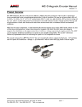
UserUser
Manual
Manual
DC425
NEMA 4X
Analog Output
Transducers
ADVANC ED
MICRO CON T ROLS INC.
Manual #: 940-0D030
DC425 Description
Offering a 4-20 mA output over single or multiple turns,
the DC425 Brushless Resolver Transducers are designed for
outdoor process control applications such as those found in
hydroelectric, water treatment and water purification
facilities. The chief consideration when designing the
DC425 Transducers was reliable operation in an environment of continuous mechanical shock and vibration,
extreme temperature and humidity variations, and exposure
to air and liquid-borne contaminates.
Reliability begins with the choice of a brushless resolver
as the absolute position feedback device. The brushless
resolver is unsurpassed by any other rotary position sensor,
such as an optical encoder or brush type resolver, in its
ability to withstand the harsh industrial environment.
Conversion from resolver position to 4-20 mA output is
accomplished through an integral electronics assembly.
This assembly utilizes surface mount technology to improve reliability and offers 1 part in 2048 resolution.
Input to the resolver is through a 5/8" stainless steel shaft
and oversized, double row, sealed bearing. The bearing is
designed to withstand a 400 lb radial load. Therefore,
pulleys or sprockets can be directly connected to the shaft.
Finally, these components are encased in a nickel
acetate-sodium dichromate anodized aluminum housing.
This is the same NEMA 4X hard coat anodizing process
used in marine and military applications.
DC input power and 4-20 mA output connections are
made either through gas tube arresters or a sealed MS
Connector. Integral MOV's provide additional lightning
and static discharge protection on both models.
Mechanical Specifications
Shaft Diameter ....... 5/8”
Shaft Loading ........ Radial: 400 lbs. max.
Axial: 200 lbs. max.
Starting Torque ...... 8 oz.in. @ 25° C
Moment of Inertia.. 20 oz-in-sec2
Weight .................... 5.5 lbs.
Environmental Specifications
Operating Temp ..... -40 to 85° C
Shock ..................... 200 g’s for 11 mSec.
Vibration ................ 5 to 2000 Hz @ 20 g’s
Enclosure ............... NEMA 4X
When properly installed.
Electrical Specifications
Input Voltage .......... 18 to 30 Vdc
24 Vdc optimal
Input Power ........... 3.75W max.
Current Output ....... 4 to 20 mA
12 bit resolution per turn.
16 bit resolution max.
Current Load .......... 650Ω max. @ 18Vdc input.
950Ω max. @ 24Vdc input.
1,250Ω max. @ 30 Vdc input.
Voltage Output ....... 0 to 10 Vdc
12 bit resolution per turn.
16 bit resolution max.
Voltage Load ......... 2KΩ minimum
DC425 –
MOUNTING
A = A-B Series 1326
Motor Mount
M = Indramat Motor
Mount†
F = Front Mount
T = Foot Mount
†
Order this type when
using an AMCI supplied
adapter plate.
2
CONNECTOR†
OUTPUT TYPE
Current Output
1 = 4 to 20 mA
2 = 0 to 20 mA
3 = 0 to 24 mA
Voltage Output
4 = 0 to 5 Vdc
5 = 0 to 10 Vdc
6 = ± 5 Vdc
7 = ± 10 Vdc
8 = –5 to 0 Vdc
9 = –10 to 0 Vdc
OUTPUT
DIRECTION
P = CCW Increasing
looking at shaft
N = CW Increasing
looking at shaft
FULL SCALE
NUMBER OF
TURNS
1 = 1 Turn
2 = 2 Turns
3 = 4 Turns
4 = 5 Turns
5 = 10 Turns
6 = 20 Turns
7 = 25 Turns
8 = 50 Turns
9 = 100 Turns
E = End
S = Side
†
MS Connector only.
CONNECTOR TYPE
1 = MS Connector
2 = Conduit Fitting
3 = Gas Tube Lightning Arrestors
ADVANC ED
MIC RO CON T RO L S INC.
Outline Drawing - Gas Tube Arrester Type
20 Gear Drive, Plymouth Industrial Park, Terryville, CT 06786
Tel: (860) 585-1254 Fax: (860) 584-1973
3
Outline Drawing - Side MS Connector Type
4
ADVANC ED
MIC RO CON T ROL S INC.
1.42 (36.1)
20 Gear Drive, Plymouth Industrial Park, Terryville, CT 06786
Tel: (860) 585-1254 Fax: (860) 584-1973
6.00 (152)
0.44 (11.2) DIA.
2 PLACES.
(MOUNTING HOLES)
MS3102E16S-1P Connector
Mates with: MS3106A16S-1S
AMCI Part# MS-16
0.700" (17.78) Max.
Total Clearance of 3.5" (89) needed
for removal of mating connector.
2.00 (50.8)
1.00 (25.4)
1.21 (30.7)
1.34 (34.0)
0.25 (6.4)
1.875 (47.6)
0.790 (20.1)
2.35 (59.7)
2.12 (53.8)
0.500
(12.7)
2.125 (54.0)
Access Holes (2 Places)
For access to flexible shaft coupler.
Olflex # 52005990 Dummy
Plugs and #52005750 O-Rings
supplied with transducer.
4.250 (108)
0.500
(12.7)
0.380
(9.65)
0.6247 (15.87)
0.6237 (15.84)
.075 X .125 DEEP SLOT
Outline Drawing - End MS Connector Type
5
Gas Tube Arrestor Wiring
RELIANCE 1304VSR2
GAS TUBE ARRESTERS
VDC
4-20 MA
DC OUTPUT
CASE GROUND
VDC SUPPLY
COMMON
REAR VIEW
INPUT DEVICE
3
POWER SUPPLY
2
SHIELD
+Vdc
BLK
WHT
WHT
BLK
BLK
BLK
YLW
YLW
-Vdc
GND
4-20 mA or 0-10 Vdc
CHASSIS
GND
-IN
4
+IN
5
1
EARTH GND
CAROL C1350 CABLE
1) a. In order for the gas tube arrestors to work properly, you must run a heavy guage drain wire from the
[Case GND] terminal to an earth ground point at the DC425. A braided cable is the preferred dain
wire.
b. Because of the gas tube arrestors, the [VDC COM] and [Case GND] terminals are tied together at the
DC425.
2) Use two, twisted, individually shielded pairs. Cable Type CAROL C1350 or equivalent such as:
Belden 9328, Alpha 2242C, or Manhattan M39351.
3) a. Use a isolated, regulated power supply with voltage output in the range of 18 to 30Vdc.
b. The power supply output must be isolated from earth ground to avoid possible ground loops between
the supply and the DC425.
4) a. For voltage output DC425’s, the input device impedence must be greater than 2KΩ.
b. For current output DC425’s, the input device impedence cannot exceed (V DC - 5) / 0.020A. This
value varies from 650Ω when VDC = 18VDC to 1250Ω when VDC = 30V DC.
5) For voltage output DC425’s, consider installing a 10KΩ resistor in parallel with the input terminals if the
input device impedence exceeds 10KΩ.
6
ADVANC ED
MIC RO CON T ROL S INC.
MS Connector Wiring
Output Connector
MS3102E16S-1P
PIN NO.
FUNCTION
A
+VDC INPUT
B
VDC COMMON
C
ANALOG OUTPUT
D
CASE GROUND
E
NO CONNECTION
F
NO CONNECTION
G
NO CONNECTION
A
F
G
E
D
B
C
INPUT DEVICE
3
POWER SUPPLY
2
SHIELD
+Vdc
A
F
G
E
D
1
1)
2)
3)
4)
5)
B
C
EARTH GND
WHT
WHT
BLK
BLK
BLK
BLK
YLW
YLW
-Vdc
GND
4-20 mA or 0-10 Vdc
CHASSIS
GND
-IN
4
+IN
5
CAROL C1350 CABLE
The DC425 case must be connected to Earth Ground. This is usually accomplished through its
mounting. If not properly grounded through its mounting, a wire from PIN D must be connected to
an Earth Ground point as close as possible to the DuraCoder. Do Not connect PIN D to the cable
shields. This can form a ground loop that may affect the operation of the DC425.
Use two, twisted, individually shielded pairs. Cable Type CAROL C1350 or equivalent such as:
Belden 9328, Alpha 2242C, or Manhattan M39351.
a. Use a regulated power supply with voltage output in the range of 18 to 30Vdc.
b. The power supply output common [VCD COM] should be connected to earth ground at the power
supply.
a. For voltage output DC425’s, the input device impedence must be greater than 2KΩ.
b. For current output DC425’s, the input device impedence cannot exceed (VDC - 5) / 0.020A. This
value varies from 650Ω when VDC = 18VDC to 1250Ω when VDC = 30VDC .
For voltage output DC425’s, consider installing a 10K Ω resistor in parallel with the input terminals if
the input device impedence exceeds 10KΩ.
DO NOT connect or disconnect the DC425 from its MS connector while power is
applied. Under limited circumstances, damage to the DC425 may result.
20 Gear Drive, Plymouth Industrial Park, Terryville, CT 06786
Tel: (860) 585-1254 Fax: (860) 584-1973
7
Important User Information
The products and application data described in this manual are useful in a wide variety of different applications.
Therefore, the user and others responsible for applying these products described herein are responsible for determining the acceptability for each application. While efforts have been made to provide accurate information within this
manual, AMCI assumes no responsibility for the application or the completeness of the information contained herein.
UNDER NO CIRCUMSTANCES WILL ADVANCED MICRO CONTROLS, INC. BE RESPONSIBLE OR
LIABLE FOR ANY DAMAGES OR LOSSES, INCLUDING INDIRECT OR CONSEQUENTIAL DAMAGES OR
LOSSES, ARISING FROM THE USE OF ANY INFORMATION CONTAINED WITHIN THIS MANUAL, OR
THE USE OF ANY PRODUCTS OR SERVICES REFERENCED HEREIN.
No patent liability is assumed by AMCI, with respect to use of information, circuits, equipment, or software
described in this manual.
The information contained within this manual is subject to change without notice.
Standard Warranty
ADVANCED MICRO CONTROLS, INC. warrants that all equipment manufactured by it will be free from
defects, under normal use, in materials and workmanship for a period of [1] year. Within this warranty period, AMCI
shall, at its option, repair or replace, free of charge, any equipment covered by this warranty which is returned,
shipping charges prepaid, within one year from date of invoice, and which upon examination proves to be defective in
material or workmanship and not caused by accident, misuse, neglect, alteration, improper installation or improper
testing.
The provisions of the “STANDARD WARRANTY” are the sole obligations of AMCI and excludes all other
warranties expressed or implied. In no event shall AMCI be liable for incidental or consequential damages or for
delay in performance of this warranty.
Returns Policy
All equipment being returned to AMCI for repair or replacement, regardless of warranty status, must have a Return
Merchandise Authorization number issued by AMCI. Call (860) 585-1254 with the model number and serial number
(if applicable) along with a description of the problem. A “RMA” number will be issued. Equipment must be shipped
to AMCI with transportation charges prepaid. Title and risk of loss or damage remains with the customer until shipment is received by AMCI.
24 Hour Technical Support Number
24 Hour technical support is available on this product.
For technical support, call (860) 583-7271. During regular business hours, (Monday - Friday, 8AM - 5PM EST), your
call will be answered by the factory. At all other times an automated system will answer your call and ask you to enter the
telephone number that you can be reached at. The system will then page an AMCI engineer on call. Please have the
product model and serial numbers as well as a description of the problem available before you call.
Revision History
This manual, 940-0D030, replaces LMDC42517. It was first released 10/20/97. The revision adds the MS end
connector drawing.
LMDC42517 updated wiring diagrams and output resolution specifications.
LMDC425C6 documented changes to the part numbering system.
LMDC42586 was the first revision of the manual.
AMCI manuals are constantly evolving entities. If you notice any errors or would like to comment on the contents of
this manual please call or fax AMCI Technical Documentation. Tel. (860) 585-1254 Fax. (860) 584-1973
A M C I – Leaders in Advanced Control Products