1
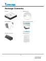
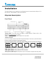
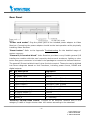
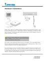
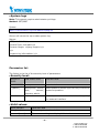
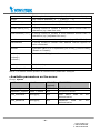
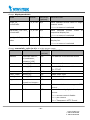
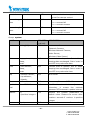
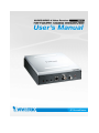
Product name: Video Receiver (RX7101) Release Date: 2009/3/26 Manual Revision: 2.1 Web site: www.vivotek.com Email: [email protected] [email protected] Made in Taiwan. ©Copyright 2000-2009. All rights reserved -1www.vivotek.com T: 886-2-82455282 F: 886-2-82455532 Before You Use This Product The use of surveillance devices may be prohibited by law in your country. It is the user’s responsibility to ensure that the operation of such devices is legal before installing this unit for its intended use. It is important to first verify that all contents received are complete according to the list in the "Package Contents" chapter. Take notice of the warnings in “Quick installation guide” before the Video Receiver is installed, then carefully read and follow the instructions in the “Installation” chapter to avoid damages due to faulty assembly and installation. This also ensures the product is used properly as intended. The Video Receiver is a network device and its use should be straightforward for those who have basic network knowledge. The “Troubleshooting” chapter in the Appendix provides remedies to the most common errors in set up and configuration. You should consult this chapter first if you run into a system error. The Video Receiver is designed for various applications including video surveillance, camera control, etc. The “How to Use” chapter suggests ways to best utilize the Video Receiver and ensure proper operations. For the creative and professional developers, the "URL Commands of The Video Receiver" chapter serves to be a helpful reference to customize existing homepages or integrating with the current web server. For paragraphs preceded by completely the warnings. the reader should use caution to understand Ignoring the warnings may result in serious hazards or injuries. -2www.vivotek.com T: 886-2-82455282 F: 886-2-82455532 Table of Contents Before You Use This Product......................................................................2 Package Contents ....................................................................................5 Installation .............................................................................................6 Physical Description............................................................................6 Front Panel ..................................................................................6 Rear Panel ...................................................................................7 Hardware Installation .........................................................................8 Software installation...........................................................................9 Initial Access to the Video Receiver..................................................... 10 Check Network Settings .............................................................. 10 Add Password to Prevent Unauthorized Access ................................ 10 How to Use ..................................................................................... 11 Authentication............................................................................ 11 Main Page ....................................................................................... 12 Primary capability of Video Receiver ................................................... 13 Video ........................................................................................ 13 Audio........................................................................................ 13 I/O ........................................................................................... 13 Definitions in Configuration ..................................................................... 15 Overview ........................................................................................ 15 System settings ............................................................................... 17 Video source settings ....................................................................... 18 Security settings .............................................................................. 26 Network settings.............................................................................. 27 Network type ............................................................................. 27 HTTP ........................................................................................ 28 Email settings.................................................................................. 29 I/O settings..................................................................................... 30 Video output .............................................................................. 30 Audio output.............................................................................. 30 Digital output............................................................................. 30 Keyboard .................................................................................. 31 System log...................................................................................... 32 -3www.vivotek.com T: 886-2-82455282 F: 886-2-82455532 Viewing system parameters............................................................... 33 Maintenance.................................................................................... 34 Language........................................................................................ 35 Appendix.............................................................................................. 36 A. Troubleshooting ........................................................................... 36 Status LED ................................................................................ 36 Reset and restore ....................................................................... 37 B. URL commands of the Video Receiver.............................................. 37 General CGI URL syntax and parameters .......................... 37 Get server parameter values........................................... 38 Set server parameter values ........................................... 39 Upgrade firmware ......................................................... 40 System logs ................................................................. 41 Parameter list ............................................................................ 41 Available parameters on the server.................................. 42 D. Technical specifications ................................................................. 53 -4www.vivotek.com T: 886-2-82455282 F: 886-2-82455532 Package Contents RX7101 Software CD Power adapter Quick installation guide Terminal connector Warranty card -5www.vivotek.com T: 886-2-82455282 F: 886-2-82455532 Installation The Video Receiver only supports one privileged account to access and configure it. In this manual, "Administrator" refers to the person. Physical Description Front Panel “Status LEDs” Two LEDs show the status of Video Receiver. Please refer to the Appendix Troubleshooting for details. “Talk” The button is reserved to support two way audio. “Switch channel” (1) In the multiple channel mode and “Sequential display” were set, to push the button to stop or start the display of sequential channel. (2) In the multiple channel mode and “Quad display” were set, to push the button to switch the channel for one run, the behavior is, -> Quad -> 1 -> 2 -> 3 -> 4 -> Quad. 1 2 3 4 1 2 3 4 1 2 3 4 “S-video output” Video output for S-video connector “BNC video output” Video output for BNC connector “RCA audio output” Audio output for RCA connector “Microphone audio input” Microphone input is reserved to support two way audio. -6www.vivotek.com T: 886-2-82455282 F: 886-2-82455532 Rear Panel “Power cord socket” Plug the power jack of the included power adapter to Video Receiver. Connecting the power adapter should be the last operation while physically installing Video Receiver. “Reset button” Refer to the Appendix Troubleshooting for the detailed usage of system recovery. “General I/O terminal block” Video Receiver provides a very flexible general I/O interface to combine with the user’s security devices such as alarms, lighting or door locks. One green connector is included in the package to connect the external devices. The general I/O terminal block has 10 pins for device control. These pins can be divided into three categories based on their functions, including power source, RS485 and digital outputs. No. Pin description Regulation 1 AC power input 24V AC 2 AC power input 24V AC 3 Digital output 1 Darlington, Max. 500mA 4 Digital output 2 Darlington, Max. 500mA 5 Digital output 3 Darlington, Max. 500mA 6 Digital output 4 Darlington, Max. 500mA 7 DC power output (+) 12V DC, Max. 0.5A 8 DC power output (-) Ground 9 RS485_A D+, non-inverting 10 RS485_B D-, inverting “Ethernet 10/100 RJ45 socket” Connect to an Ethernet network with a UTP category 5 cable of length shorter than 100 meters according to the standard. -7www.vivotek.com T: 886-2-82455282 F: 886-2-82455532 Hardware Installation Please verify that your product package contains all the accessories listed in the foregoing Package Contents. Depending on the user’s application, an Ethernet cable may be needed. The Ethernet cable should meet the specs of UTP Category 5 and not exceed 100 meters in length. Connect the power adapter jack to the Video Receiver before plugging in to the power socket. This will reduce the risk of accidental electric shock. Shut down all the peripheral devices prior to connection. The video BNC/S-Video, Ethernet cable and power adapter are essential for basic viewing function. Refer to the related configuration section for detailed description. Upon powering up, the front red LED will become lighted first and then the device will go through booting process. During the booting process, red and green LEDs will be on. After booted, the Video Receiver will standby for getting IP address. After getting IP Address, the green LED will blink every second. -8www.vivotek.com T: 886-2-82455282 F: 886-2-82455532 The Video Receiver will first detect Ethernet. If it does not connect to Ethernet, the system booting will fail. Please connect the Ethernet cable and power on again. When system boot up, the green LED will flash every second as heartbeat to indicate alive. If the green LED is off, please check the network connections. When system is alive, go to next paragraph “Software installation”. Software installation At the end of the hardware installation, users can use Installation Wizard program included in the product CDROM to find the location of the Video Receiver. There may be many Video Receivers in the local network. Users can differentiate the Video Receiver with the MAC. The MAC is printed on the label on the back of the Video Receiver body. For more detail. please refer to the user’s manual of Installation Wizard 2. Once installation is complete, the Administrator should proceed to the next section "Initial access to the Video Receiver" for necessary checks and configurations. -9www.vivotek.com T: 886-2-82455282 F: 886-2-82455532 Initial Access to the Video Receiver Check Network Settings The Video Receiver can be connected either before or immediately after software installation onto the Local Area Network. The Administrator should complete the network settings on the configuration page, including the correct subnet mask and IP address of gateway and DNS. Ask your network administrator or Internet service provider for the detail information. By default the Video Receiver requires the Administrator to run installation every time it reboots. Please refer to “Network settings” on the System Configuration page for details. If any setting is entered incorrectly and cannot proceed to setting up the Video Receiver, restore the factory settings following the steps in the “Troubleshooting” chapter of the Appendix. Add Password to Prevent Unauthorized Access The default Administrator’s password is blank and the Video Receiver initially will not ask for any password. The Administrator should immediately implement a new password as a matter of prudent security practice. Once the Administrator’s password is saved, the Video Receiver will ask for the user’s name and password before each access. The user name for the Administrator is permanently assigned as “root”. Once the password is changed, the browser will display an authentication window to ask for the new password. Once the password is set, there is no provision to recover the Administrator’s password. The only option is to restore to the original factory default settings. - 10 www.vivotek.com T: 886-2-82455282 F: 886-2-82455532 How to Use Authentication After opening the Web browser and typing in the URL of the Video Receiver, a dialogue window pops up to request a username and password. Upon successful authentication, the following figure is displayed. The foreground is the login window and the background shows the message if authentication fails. The option box can be checked to save the password for future convenience. But it is not available to the Administrator for obvious reason. *If the administrator (root user) assigns no password, everybody can access the homepage directly. - 11 www.vivotek.com T: 886-2-82455282 F: 886-2-82455532 Main Page This chapter explains the layout of the main page. It is composed of the following four sections: Logo of VIVOTEK INC., Menu, Host name, and information of Overview. Video Receiver supports maximum twenty video sources. The display mode can be single channel and multiple channels. And the multiple channel display can display four channels simultaneously or twenty-channel sequentially. In sequential mode the period of showing a channel can be adjusted. Please refer to “Video source settings” for detailed information. - 12 www.vivotek.com T: 886-2-82455282 F: 886-2-82455532 Primary capability of Video Receiver Video The Video Receiver supports maximum twenty video sources. The display mode can be single channel and multiple channels. And the multiple channel display can be display four channels simultaneously or twenty-channel sequentially. In sequential mode the period of showing a channel can be adjusted. When single channel mode is selected, only channel 1 is effective. In single channel mode, the video resolution can be set up to D1, the receiver automatically scale all other resolutions to full D1 at display. In multiple channel mode, the maximum video resolution is CIF, the receiver automatically scale all other resolutions to CIF at quad display mode and scale to D1 in sequential display mode Audio The Video Receiver only supports single audio channel output and the volume can be tuned. I/O Digital output The Video Receiver has four digital outputs, they can be configured to following any digital output of video source. Keyboard The Video Receiver supports keyboard to send PTZ commands to control PTZ camera. The Video Receiver only supports PELCO-D protocol now. The Video Receiver can send CGI command to control the PT functions of PT 7000 series. - 13 www.vivotek.com T: 886-2-82455282 F: 886-2-82455532 OSD (On Screen Display) The Video Receiver provides the following information for showing the connection or display status. If the IP address is empty, the video output shows "No Video" on the top-right corner. If the IP address is configured but the channel is disconnected, the video output shows the IP address on the top-right corner. In sequential multi-channel mode, if the periodic channel switch is stopped, there should be a channel ID on the top-right corner. - 14 www.vivotek.com T: 886-2-82455282 F: 886-2-82455532 Definitions in Configuration The Administrator can access system configuration. Each category in the left column will be explained in the following pages. The bold texts are the specific phrases on the Option pages. The Administrator may type the URL below the figure to directly enter the frame page of configuration. If the Administrator also wants to set certain options through the URL, read the reference appendix for details. Overview If the Video sources have been set, the overview page will show the basic information about the servers. In the default situation, it will show the information of “Single channel mode”. - 15 www.vivotek.com T: 886-2-82455282 F: 886-2-82455532 If the “Multiple channel mode” is selected, it will show the information of four channels. Please refer to “Video source” setting for detailed information. - 16 www.vivotek.com T: 886-2-82455282 F: 886-2-82455532 System settings "Host name" The text displays the title at the top of the banner. "Keep current date and time" Click on this to reserve the current date and time of the Video Receiver. An internal real-time clock maintains the date and time even when the power of the system is turned off. "Sync with computer time" Synchronizes the date and time of the Video Receiver with the local computer. The read-only date and time of the PC is displayed as updated. “Manual” Adjust the date and time according to what is entered by the Administrator. Notice the format in the related fields while doing the entry. “Automatic” Synchronize with the NTP server over the Internet whenever the Video Receiver starts up. It will fail if the assigned time-server cannot be reached. “NTP server” Assign the IP address or domain name of the time-server. "Time zone" Adjust the time with that of the time-servers for local settings. “Update interval” Select hourly, daily, weekly, or monthly update with the time on the NTP server. Remember to click “Save” to immediately validate the changes. Otherwise, the correct time will not be synchronized. - 17 www.vivotek.com T: 886-2-82455282 F: 886-2-82455532 Video source settings There are three parts of video source settings: “Mode”, “Video source list”, and “Display list”. - 18 www.vivotek.com T: 886-2-82455282 F: 886-2-82455532 "Mode" Select “Single channel mode”, or “multiple channel mode” which you want to display on the TV or monitor. The multiple channel mode can display four channels simultaneously (Quad display) or twenty-channel sequentially (Sequential display). “Video source list” To manage the video source list. “Auto detection” click this button to search for all detected sources in the same LAN. - 19 www.vivotek.com T: 886-2-82455282 F: 886-2-82455532 Select one of sources and click “Select” to configure it. Enter a descriptive Name for the video source, choose either Stream 1 or Stream 2 as the source, and enter the User name and Password if necessary. There are four types for RTSP streaming: Multicast, UDP, TCP and HTTP. Video and audio can be chosen independently. If you want to Use HTTP proxy, configure it first in the Network Settings page. Remember to click “Save” to enable the source settings. - 20 www.vivotek.com T: 886-2-82455282 F: 886-2-82455532 “Create” click this button if you would like to manually set up the source information. Remember to click “Save” to enable the source settings. - 21 www.vivotek.com T: 886-2-82455282 F: 886-2-82455532 Click “Close” to quit the Video information page. The video sources will be displayed in the column of video source list. For example: “Modify” Select a video source from the list and then click this button to open the Video source settings page. Remember to click “Save” after adding modification. “Delete” Select a video source from the list and then click this button to delete it. “Information” Select a video source from the list and then click this button to open the Video information window. - 22 www.vivotek.com T: 886-2-82455282 F: 886-2-82455532 “Add to display list” Click this button to add video sources to the Display list according to the Display Mode selected in the first column. "Single channel mode" You can only add one video source to the Display list, and the Video Receiver will show only one channel in video output. The video resolution can be set up to D1. Remember to click “Save” to enable the source settings. For example: - 23 www.vivotek.com T: 886-2-82455282 F: 886-2-82455532 "Multiple channel mode" The multiple channel mode can display four channels simultaneously (Quad display) or twenty-channel sequentially (Sequential display) on the analog video devices. "Sequential display" You can add up to 20 video sources to the Display list, and the video receiver will shows Channel 1, 2, 3, 4…in order with D1 resolution. Enter a “Channel switch period” for the sequential display. Click “Up” or “Down” to adjust the display order, or click “Remove” to delete the source from the Display list. Remember to click “Save” to enable the source settings. For example: - 24 www.vivotek.com T: 886-2-82455282 F: 886-2-82455532 "Quad display" You can add up to 4 video sources to the Display list, and the video receiver will show four channels at the same time. The maximum video resolution will be limited to CIF. - 25 www.vivotek.com T: 886-2-82455282 F: 886-2-82455532 Security settings “Root password” Change the Administrator’s password by typing in the new password identically in both text boxes. The typed entries will be displayed as asterisks for security purposes. <url> http://<Video Receiver>/setup/security.html <Video Receiver> is the domain name or original IP address of the Video Receiver. - 26 www.vivotek.com T: 886-2-82455282 F: 886-2-82455532 Network settings Any changes made on this page will restart the system in order to validate the changes. Make sure every field is entered correctly before clicking on . Network type “LAN” & “PPPoE” The default type is LAN. Select PPPoE if using ADSL "Get IP address automatically" & “Use fixed IP address” The default status is “Get IP address automatically”. This can be tedious having to perform software installation whenever the Video Receiver starts. Therefore, once the network settings, especially the IP address, have been entered correctly, select “Use fixed IP address” then the Video Receiver will skip installation at the next boot. The Video Receiver can automatically restart and operate normally after a power outage. Users can run IP installer to check the IP address assigned to the Video Receiver if the IP address is forgotten. “IP address” This is necessary for network identification. “Subnet mask” This is used to determine if the destination is in the same subnet. The default value is “255.255.255.0”. “Default router” This is the gateway used to forward frames to destinations in a different subnet. Invalid router setting will fail the transmission to destinations in different subnet. “Primary DNS” The primary domain name server that translates hostnames into IP addresses. “Secondary DNS” Secondary domain name server that backups the Primary DNS. “PPPoE” If using the PPPoE interface, fill in the following settings from ISP “User name” The login name of PPPoE account “Password” The password of PPPoE account “Confirm password” Input password again for confirmation - 27 www.vivotek.com T: 886-2-82455282 F: 886-2-82455532 HTTP “Http port” This can be other than the default Port 80. Once the port is changed, the users must be notified the change for the connection to be successful. For instance, when the Administrator changes the HTTP port of the Video Receiver whose IP address is 192.168.0.100 from 80 to 8080, the users must type in the web browser “http://192.168.0.100:8080” instead of “http://192.168.0.100”. “Http proxy setting” If your network need to configure Http proxy, please enter related information in the blanks. Some invalid settings may cause the system failing to respond. Change the configuration only if necessary and consult with your network supervisor or experienced users for correct settings. Once the system has lost contact, refer to Appendix A for reset and restore procedures. - 28 www.vivotek.com T: 886-2-82455282 F: 886-2-82455532 Email settings When the SMTP server support SMTP authentication, users need to give the valid user name and password to send email via the server. There are two external mail server can be configured, primary and secondary email server, The Video Receiver will use primary server as default , and use secondary server when primary server is unreachable. “Server address” The domain name or IP address of the external email server. “User name” This granted user name on the external email server. “Password” This granted password on the external email server. “Recipient email address” The email address of the recipients for snapshots or log file. Multiple recipients must be separated by semicolon, ‘;’. “Sender email address” The email address of the sender <url> http://<Video Receiver>/setup/mail.html <Video Receiver> is the domain name or original IP address of the Video Receiver. - 29 www.vivotek.com T: 886-2-82455282 F: 886-2-82455532 I/O settings Video output Video output modulation type. It can be “NTSC” or “PAL”. “Enable Overscan mode” Select it if you has smaller displayable area of your device. Audio output The audio output volume can be tuned in Video Receiver. Digital output Video Receiver supports four digital outputs, and they can be configured to follow the digital output of video source. This function is only for “Single channel mode” and “Quad display mode”. “Sequential display mode” does not support this function. In addition, if the linked video source does not support digital output, the D/O function will be disabled. The digital output will follow D/O #1~#4 (Ex: ) of channel 1~4 (Ex: ). - 30 www.vivotek.com T: 886-2-82455282 F: 886-2-82455532 Keyboard The keyboard can be connected with Video Receiver via RS485 interface. The following fields in Video Receiver must be set the same with the keyboard. “Baud rate” The transmission speed between Video Receiver and keyboard “Data bits” The length of a data “Stop bits” The length of stop bit “Parity bits” The type of parity check - 31 www.vivotek.com T: 886-2-82455282 F: 886-2-82455532 System log The Video Receiver is able to send system log to the remote server as a backup. The protocol is compliant to RFC 3164. If you have external Linux server with “syslogd” service, use “-r” option to turn on the facility for receiving log from remote machine. Or you can use some software on Windows which is compliant to RFC 3164. Check “Enable remote log” and input the “IP address” and “port” number of the log server to enable the remote log facility. In the “Current log”, it displays the current system log file. The content of the log provides useful information about configuration and connection after system boot- up. The system log is stored in the Video Receiver’s buffer area and will be overwritten when reaching a certain amount. The system will send mail with log file when system boot up if the Email settings page has been configured. - 32 www.vivotek.com T: 886-2-82455282 F: 886-2-82455532 Viewing system parameters The View parameters page lists the entire system’s parameters in alphabetical order. If you need technical assistance, please provide the information listed in this page. - 33 www.vivotek.com T: 886-2-82455282 F: 886-2-82455532 Maintenance Three actions can be selected “Reboot system” To turn off and then turn on the Video Receiver. It takes about one ~ two minutes to complete the process. “Factory default” To restore the factory default settings. Any changes made so far will be lost and the system will be reset to the initial factory settings. The system will restart and require the installer program to set up the network again. “Upgrade firmware” To upgrade the firmware on your Video receiver. It takes a few minutes to complete the process. Note that do not power off the Video receiver during the upgrade. Follow the steps below to upgrade firmware: 1. Download a new firmware file from VIVOTEK website. The file is in pkg file format. 2. Click Browse… and specify the firmware file. 3. Click Upgrade. The Video Receiver starts to upgrade and will reboot automatically when the upgrade completes. - 34 www.vivotek.com T: 886-2-82455282 F: 886-2-82455532 Language Click this button to choose a language for the user interface. Language options are available In the following list: - 35 www.vivotek.com T: 886-2-82455282 F: 886-2-82455532 Appendix A. Troubleshooting Status LED The following table lists the LED patterns in all cases. The priority 1 is the highest priority. If there are multiple statuses at the same time, the Video Receiver will show the highest priority one. 1 2 LED status Description Priority Steady Red Power on and system booting 5 Red LED unlighted Power off Steady Red + Blink Green every 1 Network works(heartbeat) 4 sec. Steady Red + Green LED unlighted 3 Network fail Steady Red + Blink Green every UART control message 3 0.15 sec. 4 Blink Red every 0.15 sec. + Blink Upgrading F/W 2 Green every 1 sec. 5 Blink Red every 0.15 sec. + Blink Restore default 1 Green every 0.15 sec. - 36 www.vivotek.com T: 886-2-82455282 F: 886-2-82455532 Reset and restore There is a button in the back side of the Video Receiver. It is used to reset the system or restore the factory default settings. RESET: Click on the button. RESTORE: 1. Press on the button continuously. 2. Wait for all LED blink fast. 3. Free the button. Restoring the factory defaults will erase any previous settings. B. URL commands of the Video Receiver For some customers who already have their own web site or web control application, the Video Receiver can be easily integrated through convenient URLs. This section lists the commands in URL format corresponding to the basic functions of the Video Receiver. General CGI URL syntax and parameters CGI parameters are written in lower-case and as one word without any underscores or other separators. When the CGI request includes internal camera parameters, the internal parameters must be written exactly as they are named in the camera or video server. The CGIs are organized in function related directories under the cgi-bin directory. The file extension of the CGI is required. Syntax: http://<servername>/cgi-bin/<subdir>[/<subdir>...]/<cgi>.<ext> [?<parameter>=<value>[&<parameter>=<value>...]] - 37 www.vivotek.com T: 886-2-82455282 F: 886-2-82455532 Get server parameter values Note: This request require administrator access Method: GET/POST Syntax: http://<servername>/cgi-bin/admin/getparam.cgi?[<parameter>] [&<parameter>…] Where the <parameter> should be <group>[_<subgroup>][_<name>] If you do not specify the any parameters, all the parameters on the server will be returned. If you specify only <group>, the parameters of related group will be returned. There may be none or multiple subgroups between group and subgroup. If you specify <group>[_<subgroup>] [_…][_<subgroupN>], the parameters of related subgroup will be returned. When query parameter values, the current parameter value are returned. Successful control requests returns parameter pairs as follows. Return: HTTP/1.0 200 OK\r\n Content-Type: text/html\r\n Context-Length: <length>\r\n \r\n <parameter pair> where <parameter pair> is <parameter>=<value>\r\n [<parameter pair>] <length> is the actual length of content. Example: request IP address and it’s response Request: http://192.168.0.123/cgi-bin/admin/getparam.cgi?network_ipaddress Response: - 38 www.vivotek.com T: 886-2-82455282 F: 886-2-82455532 HTTP/1.0 200 OK\r\n Content-Type: text/html\r\n Context-Length: 33\r\n \r\n network.ipaddress=192.168.0.123\r\n Set server parameter values Note: This request require administrator access Method: GET/POST Syntax: http://<servername>/cgi-bin/admin/setparam.cgi? [nosync=<value>&]<parameter>=<value> [&<parameter>=<value>…][&return=<return page>] parameter value description <group>[_<subgro value to assigned Assign up>]_<name>. <group>_<name>. return <return page> <value> to the parameter Redirect to the page <return page> after the parameter is assigned. The <return page> can be a full URL path or relative path according the the current path. If you omit this parameter, it will redirect to an empty page. (note: The return page can be a general HTML file(.htm, .html) or a VIVOTEK server script executable (.vspx) file. It can not be a CGI command. It can not have any extra parameters. This parameter must be put at end of parameter list) Return: HTTP/1.0 200 OK\r\n - 39 www.vivotek.com T: 886-2-82455282 F: 886-2-82455532 Content-Type: text/html\r\n Context-Length: <length>\r\n \r\n <parameter pair> where <parameter pair> is <parameter>=<value>\r\n [<parameter pair>] Only the parameters that you set and readable will be returned. Example: Set the IP address of server to 192.168.0.123 Request: http://myserver/cgi-bin/admin/setparam.cgi?Network_IPAddress=192.168.0.123 Response: HTTP/1.0 200 OK\r\n Content-Type: text/html\r\n Context-Length: 33\r\n \r\n network.ipaddress=192.168.0.123\r\n Upgrade firmware Note: This request requires administrator privilege Method: POST Syntax: http://<servername>/cgi-bin/admin/upgrade.cgi Post data: fimage=<file name>[&return=<return page>]\r\n \r\n <multipart encoded form data> Server will accept the upload file named <file name> to be upgraded the firmware and return with <return page> if indicated. - 40 www.vivotek.com T: 886-2-82455282 F: 886-2-82455532 System logs Note: This request require administrator privilege Method: GET/POST Syntax: http://<servername>/cgi-bin/admin/syslog.cgi Server will return the up-to-date system log. Return: HTTP/1.0 200 OK\r\n Content-Type: text/plain\r\n Content-Length: <syslog length>\r\n \r\n <system log information>\r\n Parameter list The follow is the list of the security level of parameters. Security level: SECURITY SUB-DIRECTORY DESCRIPTION 0 anonymous Unprotected. 6 [admin] anonymous, viewer, Administrator’s access right can fully control the LEVEL dido, camctrl, camera’s operation. operator, admin 7 N/A Internal parameters. Unable to be changed by any external interface. Valid values: VALID VALUES DESCRIPTION string[<n>] Text string shorter than ‘n’ characters password[<n>] The same as string but display ‘*’ instead - 41 www.vivotek.com T: 886-2-82455282 F: 886-2-82455532 /<n> Field length of string, password, or ip address on web page integer Any number between (-231 – 1) and (231 – 1) positive integer Any number between 0 and (232 – 1) <m> ~ <n> Any number between ‘m’ and ‘n’ domain name[<n>] A string limited to contain a domain name shorter than ‘n’ characters (eg. www.ibm.com) email address [<n>] A string limited to contain a email address shorter than ‘n’ characters (eg. [email protected]) ip address A string limited to contain an ip address (eg. 192.168.1.1) mac address A string limited to contain mac address without hyphen or colon connected boolean A boolean value 1 or 0 represents [Yes or No], [True or False], [Enable or Disable]. Enumeration. Only given values are valid. <value1>, <value2>, <value3>, … blank A blank string everything inside <> As description NOTE: The server should prevent to restart when parameter changed. Available parameters on the server Group: sipuac NAME VALUE SECURITY DESCRIPTION (get/set) requesturi_domain <ip address> 6/6 IP address of server requesturi_sipport 1025 ~ 65535 6/6 SIP port of server auth_username string[64] 6/6 User name used for SIP authentication auth_password string[64] 6/6 Password used for SIP authentication - 42 www.vivotek.com T: 886-2-82455282 F: 886-2-82455532 Group: displaymodeinfo NAME VALUE SECURITY DESCRIPTION (get/set) single_c0_ -1, 0~19 6/6 sourceindex Save selected source index in single channel mode. -1 => no source is selected sequential_c<0~19>_ -1, 0~19 6/6 sourceindex Save selected source index in sequential display list. -1 => no source is selected quad_c<0~3>_source -1, 0~19 6/6 index Save selected source index in quad display list. -1 => no source is selected Group: sourceinfo_c<0~(n-1)> n is the source count NAME VALUE SECURITY DESCRIPTION (get/set) address <domain name>, 6/6 Full address to access the media <ip address>, <blank>[128] name string[16] 6/6 Alias name of source model string[15] 6/6 Model of IP Camera or Video server. Ex: PT7137 firmver string[15] 6/6 Firmware version video_codec string[15] 6/6 Video codec type audio_codec string[15] 6/6 Audio codec type do_number 0, 6/7 Number of DO 6/6 indicate whether to support PTZ <positive integer> ptzenabled < boolean > control isptz 0~2 6/7 record "camctrl_c0_isptz" value of source. 0 => camera control disable 1 => ptz camera 2 => Transparent HTTP Tunnel - 43 www.vivotek.com T: 886-2-82455282 F: 886-2-82455532 camctrltunnel <boolean> 6/7 Indicate whether to support the http tunnel for camera control connection_st <boolean> 6/6 atus Current connection status. 0 => connect fail 1 => connect success connection_fo <boolean> 6/6 rmer Previous connection status. 0 => connect fail 1 => connect success Group: system NAME VALUE SECURITY DESCRIPTION (get/set) hostname string[40] 6/6 host name of server (Network Camera, Wireless Network Camera, Video Server, Wireless Video Server) date time ntp <yyyy/mm/dd>, 6/6 Current date of system. Set to ‘keep’ keep, keeping date unchanged. Set to ‘auto’ to auto use NTP to synchronize date. <hh:mm:ss>, 6/6 Current time of system. Set to ‘keep’ keep, keeping time unchanged. Set to ‘auto’ to auto use NTP to synchronize time. <domain name>, 6/6 NTP server <ip address>, <blank> timezone -12 ~ 12 6/6 time zone, 5 means GMT +5 updateinte 0 ~ 2592000 6/6 0 to Disable automatic time adjustment, rval otherwise, it means the seconds between NTP automatic update interval. restore 0, 7/6 <positive integer> Restore the system parameters to default value. Restart the server after <value> seconds if <value> is positive integer. reset 0, -1, 7/6 Restart the server after <value> - 44 www.vivotek.com T: 886-2-82455282 F: 886-2-82455532 <positive integer> restoreexc 0, eptnet <positive integer> seconds if <value> is non-negative. 7/6 Restore the system parameters to default value except (ipaddress, subnet, router, dns1, dns2, ddns settings). Restart the server after <value> seconds if <value> is positive integer. SubGroup of system: info (The fields in this group are unchangeable.) NAME VALUE SECURITY DESCRIPTION (get/set) modelname string[40] 0/7 ODM specific model name of server (eg. DCS3220) serialnumber <mac 0/7 12 characters mac address without hyphen address> firmwareversio string[40] connected 0/7 The version of firmware, including model, n company, and version number in the format <MODEL-BRAND-VERSION> language_coun <integer> 0/7 number of webpage language available on t language_i<0 the server string[16] 0/7 Available language lists ~(count-1)> Group: security NAME VALUE SECURITY DESCRIPTION (get/set) user_i0_name string[64]/18 6/7 User’s name, only root’s account user_i0_pass password[64] 6/6 User’s password, only root’s account admin 6/7 Privilege of user i0 1 6/7 User count /18 user_i0_privile ge usercount - 45 www.vivotek.com T: 886-2-82455282 F: 886-2-82455532 Group: source_c<0~(n-1)> n is the source count NAME VALUE SECURITY DESCRIPTION (get/set) address <domain name>, 6/6 IP Camera or Video server <ip address>, <blank>[128]/40 port 80, 1025 ~ 65535 6/6 HTTP port username string[64]/16 6/6 User’s name password password[64]/16 6/6 User’s password protocol multicast, 6/6 The protocol of streaming 6/6 The media for streaming udp, tcp, http media av, audio, video autoconnect <boolean> 6/6 Auto connect to the server enablehttpproxy <boolean> 6/6 0 => disable http proxy 1 => enable http proxy Group: videoout NAME VALUE SECURITY DESCRIPTION (get/set) channelmode single, 6/6 Single channel mode always shows the multiple channel 1. There are two display mode in multiple channel mode. displaymode sequential, 6/6 Display mode in multiple channel mode 6/6 The channel switch period in sequential quad switchperiod 5-99 display mode modulation ntsc, 6/6 Modulation for video output 6/6 Support OverScan mode pal overscan <boolean> - 46 www.vivotek.com T: 886-2-82455282 F: 886-2-82455532 Group: audioin NAME VALUE SECURITY DESCRIPTION (get/set) c0_gain 0~31 6/6 Gain of input c0_s0_codectype g711 6/7 codec type for audio input c0_s0_g711_mode pcmu, pcma 6/7 set audio mode for input c0_s0_g711_sampler 8000,16000, 6/7 Set sample rate of G711 codec ate 32000,44000 Group: audioout NAME VALUE SECURITY DESCRIPTION (get/set) enable <boolean> 6/7 Enable audio output channel 0~3 6/6 Output audio channel volume 1~100 6/6 The volume of audio output SECURITY DESCRIPTION Group: network NAME VALUE (get/set) type lan, 6/6 Network connection type 6/6 1 => get ipaddress, subnet, router, dns1, pppoe resetip <boolean> dns2 from DHCP server at next reboot 0 => use preset ipaddress, subnet, rounter, dns1, and dns2 ipaddress <ip 6/6 IP address of server address>[15]/16 subnet <ip address> 6/6 subnet mask router <ip address> 6/6 default gateway dns1 <ip address> 6/6 primary DNS server dns2 <ip address> 6/6 secondary DNS server - 47 www.vivotek.com T: 886-2-82455282 F: 886-2-82455532 Subgroup of network: http NAME VALUE SECURITY DESCRIPTION (get/set) port 80, 1025 ~ 65535 6/6 HTTP port SECURITY DESCRIPTION Subgroup of network: ftp NAME VALUE (get/set) port 21, 1025 ~ 65535 6/6 FTP port SECURITY DESCRIPTION Subgroup of network: pppoe NAME VALUE (get/set) user string[80]/40 6/6 PPPoE account user name pass password[64]/64 6/6 PPPoE account password Subgroup of network: httpproxy NAME VALUE SECURITY DESCRIPTION (get/set) address <ip address> 6/6 IP address of http proxy server port 1 ~ 65535 6/6 HTTP proxy port username string[64]/16 6/6 The username to login in the http proxy server. password string[64]/16 6/6 The password of the user. Group: server NAME VALUE SECURITY DESCRIPTION (get/set) email_ string[128]/ i<0~(n-1)>_address 40 email_ string[64]/4 i<0~(n-1)>_username 0 email_ string[64]/4 i<0~(n-1)>_passwd 0 6/6 The address of SMTP server 6/6 The username to login in the server 6/6 The password of the user - 48 www.vivotek.com T: 886-2-82455282 F: 886-2-82455532 email_ string[128]/ i<0~(n-1)>_senderemail 40 email_ string[128]/ i<0~(n-1)>_recipientemail 40 6/6 The email address of sender 6/6 The email address of recipient Group: do_i<0~(ndo-1)> (capability.ndo > 0) NAME VALUE SECURITY DESCRIPTION (get/set) enable <boolean> 6/6 Enable digital output followchannel 0~3 6/6 The DO status follows channel 1,2,3,4. serverdo 0(~3) 6/6 The DO index of server Group:uart_i<0~(n-1)> n is uart port count (capability.nuart>0) NAME VALUE SECURITY DESCRIPTION (get/set) baudrate 110, 300, 600, 1200, 6/6 set baud rate of COM port 2400, 4800, 9600, 19200,38400 databit 5,6,7,8 6/6 stopbit 1,2 6/6 01 2-1.5 , data bit is 5 2-2 paritybit 6/6 none, odd, even Group: syslog NAME VALUE SECURITY DESCRIPTION (get/set) enableremotelog <boolean> 6/6 enable remote log serverip <IP address> 6/6 Log server IP address serverport 514, 6/6 Server port used for log 1025~65535 - 49 www.vivotek.com T: 886-2-82455282 F: 886-2-82455532 Group: capability NAME VALUE SECURITY DESCRIPTION (get/set) api_httpversion 0201a 0/7 The HTTP API version. nir 0, 0/7 number of IR interface 0/7 number of digital input 0/7 number of digital output 0/7 number of audio input 0/7 number of audio output <positive integer> ndi 0, <positive integer> ndo 0, <positive integer> naudioin 0, <positive integer> naudioout 0, <positive integer> nvideoin <positive integer> 0/7 number of video input nvideochannel <positive integer> 0/7 number of video channel naudiochannel 0,<positive 0/7 number of audio channel 0/7 number of UART interface 0/7 indicate whether to support integer> nuart 0, <positive integer> ptzenabled < boolean > PTZ control ptzenabledclient < boolean > 0/7 indicate whether to support PTZ control at client side protocol_https < boolean > 0/7 indicate whether to support http over SSL protocol_rtsp < boolean > 0/7 indicate whether to support rtsp protocol_sip <boolean> 0/7 indicate whether to support sip protocol_rtp_multicast_ <boolean> 0/7 scalable protocol_rtp_multicast_ indicate whether to support scalable multicast <boolean> 0/7 indicate whether to support - 50 www.vivotek.com T: 886-2-82455282 F: 886-2-82455532 backchannel protocol_rtp_tcp backchannel multicast <boolean> 0/7 indicate whether to support rtp over tcp protocol_rtp_http <boolean> 0/7 indicate whether to support rtp over http protocol_spush_mjpeg <boolean> 0/7 indicate whether to support server push motion jpeg protocol_snmp <boolean> 0/7 indicate whether to support snmp videoin_resolution <a list of the 0/7 available resolutions list available resolution separates by comma) videoin_codec <a list of available types the 0/7 available codec list codec separaters by comma) videoout_type 0, 1, 2, 3 0/7 0 => no 1 => NTSC 2 => PAL 3 => BOTH audio_aec <boolean> 0/7 indicate whether to support acoustic echo cancellation audio_extmic <boolean> 0/7 indicate whether to support external microphone input audio_linein <boolean> 0/7 indicate whether to support external line input audio_lineout <boolean> 0/7 indicate whether to support line output audio_headphoneout <boolean> 0/7 indicate whether to support headphone output audioin_codec <a list of available the 0/7 codec available codec list audio input - 51 www.vivotek.com T: 886-2-82455282 F: 886-2-82455532 for types separaters by comma> camctrl_httptunnel <boolean> 0/7 Indicate whether to support the http tunnel for camera control camctrl_httptunnelclient <boolean> 0/7 Indicate whether to support the http tunnel for camera control at client side uart_httptunnel <boolean> 0/7 Indicate whether to support the http tunnel for uart transfer uart_httptunnelclient <boolean> 0/7 Indicate whether to support the http tunnel for uart transfer at client side transmission_mode 0/7 Tx, Indicate what kind Rx, transmission Both machine used. TX: server, Rx: receiver mode of box, the Both: DVR?. network_wire <boolean> 0/7 Indicate whether to support the Ethernet network_wireless <boolean> 0/7 Indicate whether to support the wireless wireless_s802dot11b <boolean> 0/7 Indicate whether to support the wireless 802.11b+ wireless_s802dot11g <boolean> 0/7 Indicate whether to support the wireless 802.11g wireless_encrypt_wep <boolean> 0/7 Indicate whether to support the wireless WEP wireless_encrypt_wpa <boolean> 0/7 Indicate whether to support the wireless WPA wireless_encrypt_wpa2 <boolean> 0/7 Indicate whether to support the wireless WPA2 - 52 www.vivotek.com T: 886-2-82455282 F: 886-2-82455532 D. Technical specifications - 53 www.vivotek.com T: 886-2-82455282 F: 886-2-82455532 Technology License Notice MPEG-4 AAC Technology THIS PRODUCT IS LICENSED UNDER THE MPEG-4 AAC AUDIO PATENT LICENSE. THIS PRODUCT MAY NOT BE DECOMPILED, REVERSE-ENGINEERED OR COPIED, EXCEPT REGARD TO PC SOFTWARE, YOU MAY MAKE SINGLE COPIES FOR ARCHIVAL PURPOSES. FOR MORE INFORMATION, PLEASE REFER TO HTTP://WWW.VIALICENSING.COM. MPEG-4 Visual Technology THIS PRODUCT IS LICENSED UNDER THE MPEG-4 VISUAL PATENT PORTFOLIO LICENSE FOR THE PERSONAL AND NON-COMMERCIAL USE OF A CONSUMER FOR (i) ENCODING VIDEO IN COMPLIANCE WITH THE MPEG-4 VISUAL STANDARD ("MPEG-4 VIDEO") AND/OR (ii) DECODING MPEG-4 VIDEO THAT WAS ENCODED BY A CONSUMER ENGAGED IN A PERSONAL AND NON-COMMERCIAL ACTIVITY AND/OR WAS OBTAINED FROM A VIDEO PROVIDER LICENSED BY MPEG LA TO PROVIDE MPEG-4 VIDEO. NO LICENSE IS GRANTED OR SHALL BE IMPLIED FOR ANY OTHER USE. ADDITIONAL INFORMATION INCLUDING THAT RELATING TO PROMOTIONAL, INTERNAL AND COMMERCIAL USES AND LICENSING MAY BE OBTAINED FROM MPEG LA, LLC. SEE HTTP://WWW.MPEGLA.COM. AMR-NB Standard THIS PRODUCT IS LICENSED UNDER THE AMR-NB STANDARD PATENT LICENSE AGREEMENT. WITH RESPECT TO THE USE OF THIS PRODUCT, THE FOLLOWING LICENSORS’ PATENTS MAY APPLY: TELEFONAKIEBOLAGET ERICSSON AB: US PAT. 6192335; 6275798; 6029125; 6424938; 6058359. NOKIA CORPORATION: US PAT. 5946651; 6199035. VOICEAGE CORPORATION: AT PAT. 0516621; BE PAT. 0516621; CA PAT. 2010830; CH PAT. 0516621; DE PAT. 0516621; DK PAT. 0516621; ES PAT. 0516621; FR PAT. 0516621; GB PAT. 0516621; GR PAT. 0516621; IT PAT. 0516621; LI PAT. 0516621; LU PAT. 0516621; NL PAT. 0516621; SE PAT 0516621; US PAT 5444816; AT PAT. 819303/AT E 198805T1; AU PAT. 697256; BE PAT. 819303; BR PAT. 9604838-7; CA PAT. 2216315; CH PAT. 819303; CN PAT. ZL96193827.7; DE PAT. 819303/DE69611607T2; DK PAT. 819303; ES PAT. 819303; EP PAT. 819303; FR PAT. 819303; GB PAT. 819303; IT PAT. 819303; JP PAT. APP. 8-529817; NL PAT. 819303; SE PAT. 819303; US PAT. 5664053. THE LIST MAY BE UPDATED FROM TIME TO TIME BY LICENSORS AND A CURRENT VERSION OF WHICH IS AVAILABLE ON LICENSOR’S WEBSITE AT HTTP://WWW.VOICEAGE.COM. . - 54 www.vivotek.com T: 886-2-82455282 F: 886-2-82455532 Electromagnetic Compatibility (EMC) FCC Statement This device compiles with FCC Rules Part 15. Operation is subject to the following two conditions. ■ This device may not cause harmful interference, and ■ This device must accept any interference received, including interference that may cause undesired operation. This equipment has been tested and found to comply with the limits for a Class B digital device, pursuant to Part 15 of the FCC Rules. These limits are designed to provide reasonable protection against harmful interference in a residential installation. This equipment generates, uses and can radiate radio frequency energy and, if not installed and used in accordance with the instructions, may cause harmful interference to radio communications. However, there is no guarantee that interference will not occur in a partial installation. If this equipment does cause harmful interference to radio or television reception, which can be determined by turning the equipment off and on, the user is encouraged to try to correct the interference by one or more of the following measures: ■ Reorient or relocate the receiving antenna. ■ Increase the separation between the equipment and receiver. ■ Connect the equipment into an outlet on a circuit different from that to which the receiver is connected. ■ Consult the dealer or an experienced radio/TV technician for help. Shielded interface cables must be used in order to comply with emission limits. CE Mark Warning This is a Class B product. In a domestic environment, this product may cause radio interference, in which case the user may be required to take adequate measures. Liability VIVOTEK Inc. cannot be held responsible for any technical or typographical errors and reserves the right to make changes to the product and manuals without prior notice. VIVOTEK Inc. makes no warranty of any kind with regard to the material contained within this document, including, but not limited to, the implied warranties of merchantability and fitness for any particular purpose.