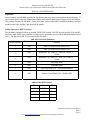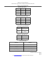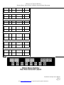
1
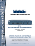
I N S TA L L AT I O N A N D O P E R AT I O N MANUAL for the Broadcast Tools® SS 16.4 Sixteen Input, Quad Output Stereo Audio Matrix Switcher Broadcast Tools® is a registered trademark of Broadcast Tools, Inc. Copyright 1989 - 2004 by Broadcast Tools, Inc. All rights reserved. No part of this document may be reproduced or distributed without permission. A L L S P E C IF IC AT IO N S A N D F E AT U R E S F O R T H I S P R O D U C T A R E S U B JE C T TO C H A N G E W IT H O U T N O T IC E Firmware Version 1.23 or above Manual update 01-12-2004 Manufactured with pride in the USA BROADCAST TOOLS® SS 16.4 SIXTEEN INPUT, QUAD OUTPUT STEREO AUDIO MATRIX SWITCHER TABLE OF CONTENTS Introduction 3 Safety Information 3 Who to Contact for Help 3 Product Description 4 Installation Guidelines 7 Inspection Setting Operation “Dip” Switches: Power-Up Feature Macro Feature Mounting Power Supply Connection Connecting Inputs/Outputs/Relays Adjusting Input and Output Levels Input Channel Expansion Remote Control Serial Interface Connecting the RS-232 Serial Port Serial Control Set-up Commands Output Port Control Pulse Stretcher “PIP” Connector Digital Inputs 5 6 7 7 7 7 8 8 9 9 9 11 14 16 18 19 19 Specifications 22 Warranty 23 Schematic and Component Layout Appendix Installation and Operation Manual SS16.4 Page 2 Visit www.broadcasttools.com for important product update information. BROADCAST TOOLS® SS 16.4 SIXTEEN INPUT, QUAD OUTPUT STEREO AUDIO MATRIX SWITCHER INTRODUCTION Thank you for your purchase of a Broadcast Tools® SS 16.4 Sixteen Input, Quad Output Stereo Audio Matrix Switcher (referred to as the SS 16.4 throughout this manual). We’re confident that this product will give you many years of dependable service. This manual is intended to give you all the information needed to install and operate the Broadcast Tools® SS 16.4. NOTE: This manual should be read thoroughly before installation and operation. SAFETY INFORMATION Only qualified personnel should install Broadcast Tools® products. Incorrect or inappropriate use and/or installation could result in a hazardous condition. CAUTION! Broadcast Tools® Products, as with any electronic device, can fail without warning. Do not use this product in applications where a life threatening condition could result due to failure. WHO TO CONTACT FOR HELP If you have any questions regarding your product or you need assistance, please contact your distributor from whom you purchased this equipment. If you would like more information about Broadcast Tools® products, you may reach us at: Broadcast Tools, Inc. 131 State Street Sedro-Woolley, WA 98284-1540 USA Voice: 360 . 854 . 9559 Fax: 360 . 854 . 9479 Internet Home Page: E-mail: www.broadcasttools.com [email protected] THANK YOU FOR CHOOSING BROADCAST TOOLS® BRAND PRODUCTS! Installation and Operation Manual SS16.4 Page 3 Visit www.broadcasttools.com for important product update information. BROADCAST TOOLS® SS 16.4 SIXTEEN INPUT, QUAD OUTPUT STEREO AUDIO MATRIX SWITCHER PRODUCT DESCRIPTION The Broadcast Tools® SS 16.4 provides matrix audio switching of 16 stereo inputs to 4 stereo plus 4 monaural outputs. Matrix switching allows any/or all inputs to be assigned to any/or all outputs. The SS 16.4 may be controlled via front panel switches, contact closures, 5-volt TTL/CMOS logic and/or the multi-drop RS-232 or RS-485 serial port. Installation is simplified with removable screw terminals (Euro). PRODUCT FEATURES • True matrix switching, any or all inputs may be assigned to any or all outputs. • Three switching modes. Interlock, overlap and mix. • Logic functions via microprocessor and non-volatile memory • Internal audio activity/silence sensors monitor all four-output channels. Each is equipped with front panel “ACT” LED indicators; adjustable alarm delay and restore duration. Sensitivity is factory set at -34db. • Front panel input selection switches are provided for each input channel with separate output indicator LED’s • Power-up selection of inputs to outputs, mute or last source selected. • Sixteen user configured macros • Most configuration options via rear panel dipswitches. • 24 input GPI port (Remote Control or PIP) with LED indicator. • 16 open collector channel status outputs or programmable via burst commands. • 8 spst relay outputs. Programmable via burst commands. • Multi-turn input level controls. • Single turn output level controls • Electronically balanced stereo inputs. • Electronically balanced stereo and monaural outputs. • Remote control of front panel functions and status. • Multidrop RS-232 or RS-485 serial port with data activity LED. • Multiple units may be cascaded to expand inputs. • Depluggable screw (EURO) terminals for ALL connections. • 2-RU chassis Installation and Operation Manual SS16.4 Page 4 Visit www.broadcasttools.com for important product update information. BROADCAST TOOLS® SS 16.4 SIXTEEN INPUT, QUAD OUTPUT STEREO AUDIO MATRIX SWITCHER PRODUCT DESCRIPTION Front Panel: The SS 16.4 is a 2 - RU device (19”w x 3.50”h x 10”d). The front panel supports 23 selection switches and 72 LED indicators. Rear Panel: Installation is simplified with pluggable screw terminal connectors. The SS 16.4 may be pre-wired and installed in minutes. The multi-drop RS-485 and RS-232 modular connection and a 7 pin “DIN” power connector is provided for the supplied “Lump in the Line” power supply. Switches: Twenty-three pushbutton switches (The “PGM” switch is hidden) that may be used to mute or select audio inputs and output channels. Sixteen macros may also be programmed and selected. The input channels may be programmed for the following operations: • Overlap - Overlap one audio source with another while the button for the second source is held down. Both channels will be fed to the output until the second button is released, at which time the first audio source will be switched off. • Mix - May connect more than one input at a time to any given output - Push once to connect input, again to disconnect. • Interlock - Connecting one input to any output disconnects all other inputs from that output LED Indicators: The SS 16.4’s 72 front panel LED indicators provide operational display of the following information: • • • • • Four indicators per input channel display which output channel the input is connected. Unit power and serial data activity. “PIP” Parallel Input Port active, indicating any change with the 24 input “Pulse Stretcher” ports. Four audio activity LED’s and detectors. SS 16.4 selected or active indicates that the multi-drop RS-232 or RS-485 serial port has been addressed. Installation and Operation Manual SS16.4 Page 5 Visit www.broadcasttools.com for important product update information. BROADCAST TOOLS® SS 16.4 SIXTEEN INPUT, QUAD OUTPUT STEREO AUDIO MATRIX SWITCHER PRODUCT DESCRIPTION Controls: Audio Inputs: Each of the 16 stereo inputs are balanced bridging (20KΩ) at a nominal line level of +4dBu. Sufficient gain is provided for unbalanced consumer level products. Multi-turn level controls are provided for each channel. Terminating resistors may be added to the connector, if needed. Audio Outputs: The SS 16.4 provides four selectable balanced stereo outputs. Four balanced monaural outputs are also provided which follow their respective stereo outputs. “ACT” Audio Activity Sensor: The SS 16.4 contains individual audio activity sensors, which may be used as silence sensors for each of the four stereo output channels. For each channel, a detector monitors the sum of each stereo channel. The factory default time delay and restore delay is set at 10 seconds, with a fixed signal threshold of 32dB. Upon silence detection for the user-selected time, the “ACT” indicator is extinguished for the duration of silence and serial “ACT” status is sent. When audio returns and the restore time delay has expired, the front panel “ACT” led will illuminate and serial “ACT” status is sent. The “ACT” may be programmed for: • • Number of seconds of silence that must be present before an alarm state is reached. Number of seconds of audio presence after an alarm state before the “ACT” led illuminates. PIP Input: The Parallel Input Port (GPI) with the Programmable Pulse Stretcher provides 24 pulse-stretched parallel 5-volt TTL/CMOS compatible inputs. The inputs are pulled high to 5 volts through a 20KΩ resistor and are activated by pulling the input to ground. These inputs supply status to any serial polling device (when the unit ID is set to 0, no polling of inputs is required). For all PIP inputs a pulse of specified minimum input duration (000 to 2.55 Seconds) causes the status to go true until the end of the input pulse. The pulse width may vary between the specified value and 10 ms less than that value. This allows the polling computer more time to detect an input change. Installation and Operation Manual SS16.4 Page 6 Visit www.broadcasttools.com for important product update information. BROADCAST TOOLS® SS 16.4 SIXTEEN INPUT, QUAD OUTPUT STEREO AUDIO MATRIX SWITCHER PRODUCT DESCRIPTION “Open Collector” Status Outputs, 16 Port Output Control The SS 16.4 provides sixteen open collector status outputs. The status outputs may be configured to operate in one of three modes: • • • The status outputs follow the associated channel. The status outputs a one-second pulse when the associated channel is selected. Burst mode control Relay Outputs, 8 Port Output Control: The SS 16.4 contains 8 spst (normally open) relays. Each relay may be latched on, latched off or pulsed on by serial burst commands. The relay “pulse” time may be set from zero to 9.9 seconds. The default pulse length is one second. Serial Communication: The SS 16.4’s serial communication may be configured for either multi-drop RS-232 or RS485, allowing up to 8 - SS 16.4’s on the same computers serial port. Burst mode allows a computer or ASCII terminal to control and interrogate the unit. This section defines all burst mode commands. Each burst mode commands starts with an asterisk (“*”). Next is a single decimal digit that corresponds to the unit (ID) address 0-3. Following that are one or more ASCII characters specifying the command. No carriagereturn or line-feed is required to terminate the command except for those few commands of variable length, if the maximum length is not sent. If acknowledgements are enabled, successful commands are responded to with “RRR” while errors get an “EEE” response. The syntax of each command is given below. The syntax shows the command exactly as it should be sent, except that lower case characters represent values that should be substituted: User Programming: The SS 16.4 programming is stored in non-volatile memory. Configurations are set with selection dipswitches and computer commands. Installation and Operation Manual SS16.4 Page 7 Visit www.broadcasttools.com for important product update information. BROADCAST TOOLS® SS 16.4 SIXTEEN INPUT, QUAD OUTPUT STEREO AUDIO MATRIX SWITCHER INSTALLATION GUIDELINES Inspection: Please examine your SS 16.4 carefully for any damage that may have been sustained during shipping. If any is noted, please notify the shipper immediately and retain the packaging for inspection by the shipper. The package contains the SS 16.4, “Lump in the line” power transformer, Installation manual, reversed modular serial cable and the 9-pin D-Sub (S 9) adapter. Setting Operation “DIP” Switches: The SS 16.4 is equipped with an 8-position “PGM” DIP Switch. The DIP Switch specifies 2 bit unit ID, baud rate, audio modes (mix, interlock, overlap), power up modes, remote control and other features listed below. The dipswitch (SW 24) is located on the rear pane.. Switch Number DIP (SW-24) Switch Functions Default Setting Function 1 OFF Add 1 to Address (base address is 0) 2 OFF Add 2 to Address (base address is 0) OFF Baud Rate: 00 - 9600, 01 - 2400, 10 - 19200, 11 38400 OFF Baud Rate: 00 - 9600, 01 - 2400, 10 - 19200, 11 – 38400 5 OFF Switching Mode 6 OFF Switching Mode 7 OFF Power up mode (Off = User programmable) 8 OFF Remote ControlMode (ON = Enables PIP) 3 4 Address (ID) DIP Switches SW24 – 1 SW24 – 2 ID OFF OFF ID = 0 ON OFF ID = 1 OFF ON ID = 2 ON ON ID = 3 Installation and Operation Manual SS16.4 Page 8 Visit www.broadcasttools.com for important product update information. BROADCAST TOOLS® SS 16.4 SIXTEEN INPUT, QUAD OUTPUT STEREO AUDIO MATRIX SWITCHER INSTALLATION GUIDELINES Baud Rate DIP Switches SW24 - 3 SW24 – 4 Baud Rate OFF OFF 9600 ON OFF 2400 OFF ON 19200 ON ON 38400 Audio Switching Mode DIP Switches SW24 - 5 SW24 – 6 Mode OFF OFF Overlap ON OFF Interlock OFF ON Interlock ON ON Mix Power up/Last source DIP Switch SW24 – 7 Function OFF User Programmable ON Last Source(s) selected PIP/Remote Mode DIP Switch SW24 - 8 Function OFF Remote Control ON PIP enabled Front Panel Switches Switch(es) Function 1-16 Channel Inputs Output 1,2,3,4 Output selector MUTE Mutes selected channel MACRO Selects up to 16 Macro’s Hidden “PGM” Special programming functions Installation and Operation Manual SS16.4 Page 9 Visit www.broadcasttools.com for important product update information. BROADCAST TOOLS® SS 16.4 SIXTEEN INPUT, QUAD OUTPUT STEREO AUDIO MATRIX SWITCHER INSTALLATION GUIDELINES Operation Action • Hold down the Output 1 button • Push the Channel Button • Hold down the Output 2 button • Push the Channel Button • Hold down the Output 3 button • Push the Channel Button • Hold down the Output 4 button • Push the Channel Button Result Channel is connected to output 1. To mute the active channel, simultaneously hold down the mute switch and press the desired input channel button. Channel is connected to output 2. To mute the active channel, simultaneously hold down the mute switch and press the desired input channel button. Channel is connected to output 3. To mute the active channel, simultaneously hold down the mute switch and press the desired input channel button. Channel is connected to output 4. To mute the active channel, simultaneously hold down the mute switch and press the desired input channel button. Power-Up Feature, user programmable: To select a channel configuration at power-up: 1 - Verify that dipswitch 24-7 is OFF. 2 - Select the desired input and output channel configuration. 3 - Press and hold the hidden “PGM” button with a non-metallic object. 4 - Press the output 1 button. 5 - The macro led will flash for 2 seconds. 6 - Release both switches. 7 - Your power up configuration is saved. Power-Up Feature, last source selected: 1 - Verify that dipswitch 24-7 is ON. 2 – The SS 16.4 will power up with whatever channel configuration was present at power off. Macro Feature: Set the input/output configuration desired, press the hidden “PGM” button with a non-metallic object and then press the macro button along with the desired input channel button. To recall the macro, press the macro button and any one of the desired stored macro’s using the input channel buttons. Installation and Operation Manual SS16.4 Page 10 Visit www.broadcasttools.com for important product update information. BROADCAST TOOLS® SS 16.4 SIXTEEN INPUT, QUAD OUTPUT STEREO AUDIO MATRIX SWITCHER INSTALLATION GUIDELINES Mounting: The SS 16.4 is designed to be rack mounted in a standard 19” rack, (2 – RU). It should be mounted in an area that is accessible from the rear and preferably away from sources of heat. We recommend before permanently installing the SS 16.4, you bench test and become familiar with the operation of the unit. Power Supply Connection: Install the 7-pin “DIN” connector into the DIN receptacle on the SS 16.4. Mount the “LUMP” in a convenient location. When ready, plug the “Lump in the Line” AC cord into the appropriate AC receptacle. Connecting The Audio Inputs, Outputs, PIP, remote control inputs and OC/Relays: NOTE: Refer to the grid and rear panel diagram on pages 22 and 23 The SS 16.4 interfaces to your audio equipment through depluggable rear panel screw terminals. Refer to the supplied connection template. Remove each screw terminal, strip each conductor, insert the conductor into the terminal and screw down the capture screw. The terminals accommodate wire sizes from 16 - 28 AWG solid or stranded wire. Connections may be made to the + and - inputs for balanced operation, or to the + input and grounding the - side for unbalanced input operation. Connections can be made to the + and - outputs for balanced operation, or to the + output and ground for unbalanced output operation. CAUTION! Never connect either the + or - outputs to ground. The input impedance is high, 600Ω terminations may be installed on the connector. CAUTION! Installation of the SS 16.4 in high RF environments should be performed with care. Shielded cable is suggested for all control, audio inputs and outputs. All shields should be tied to the “CHASSIS GROUND” terminal. The station ground should be connected to the chassis ground screw (CH1) located behind J1 as viewed from the rear. For lightning protection devices, check out www.polyphaser.com and www.itwlinx.com. It is recommended that all cables connected to the SS 16.4 be looped through ferrite cores to suppress RF. Surge protection with RF filtering such as the Tripp Lite “ISOBAR 4” is also suggested for the power transformer. The purchase of an inexpensive uninterruptible power supply (UPS) will provide back up in case of power outages. Check out our web site for lightning protection links. Installation and Operation Manual SS16.4 Page 11 Visit www.broadcasttools.com for important product update information. BROADCAST TOOLS® SS 16.4 SIXTEEN INPUT, QUAD OUTPUT STEREO AUDIO MATRIX SWITCHER INSTALLATION GUIDELINES Adjusting Input and Output Levels: Once the input and output connections have been made, the input levels can be set. The switcher is factory set for unity. Maximum input levels should be limited to + 27dbu. Should input levels need to be changed, they are accessible from the rear panel. Each input trimmer has one adjustment per channel. Output adjustments must be made internally on the main circuit board. The controls are labeled “Output Levels”. Input Channel Expansion: Input expansion may be accomplished by connecting a shielded cable between the first units EXT 1+ input terminal and the second units + unbalanced output. The shield should be connected to the ground terminal. Follow the same procedure for the EXT +1 right channel. The above example provides 32 inputs, with the first unit providing the main output. Remote Control: Most front panel functions of the SS 16.4 may be remote controlled via removable screw terminals located on the rear panel. The SS 16.4 accepts momentary contact closures, open collector or 5volt TTL/CMOS logic levels. Open collector status and relays are provided. Serial Interface: The Serial Interface is jumper selectable. It uses either a multi-drop RS-232 transceiver, or a RS485 transceiver. It is assumed to always be in a multi-drop configuration. Software does not distinguish between RS-232 and RS-485 operation. It always switches both transceivers between transmit and receive mode. Installation and Operation Manual SS16.4 Page 12 Visit www.broadcasttools.com for important product update information. BROADCAST TOOLS® SS 16.4 SIXTEEN INPUT, QUAD OUTPUT STEREO AUDIO MATRIX SWITCHER INSTALLATION GUIDELINES Front panel LED indicators: Front Panel LED’s Number Activation Event/Mode Activation Behavior 16 Green State of Connection On if connected Of LED’s Inputs connected to Output 1 Inputs connected to Output 2 Inputs connected to Output3 Inputs connected to Output 4 Power Status 16 Red State of Connection On if connected 16 Yellow State of Connection On if connected 16 Green State of Connection On if connected 1 Green Valid Power On Lock/Active 1 Green Front panel locked On if locked Macro “PIP” Active 1 Green 1 Yellow Macro selection Any valid “PIP” input On if active On if active “ACT 1” 1 Green Audio Activity for OP 1 On if active audio “ACT 2” 1 Green Audio Activity for OP 2 On if active audio “ACT 3” 1 Green Audio Activity for OP 3 On if active audio “ACT 4” 1 Green Audio Activity for OP 4 On if active audio Front Panel Switches: Switch(es) Function 1-16 Input Channel or Macro 1-16 Output 1 Output 1 selection Output 2 Output 2 selection Output 3 Output 3 selection Output 4 Output 4 selection Mute Turn off selected I/O Macro Select any one of 16 Macros Hidden “PGM” Special programming functions Installation and Operation Manual SS16.4 Page 13 Visit www.broadcasttools.com for important product update information. BROADCAST TOOLS® SS 16.4 SIXTEEN INPUT, QUAD OUTPUT STEREO AUDIO MATRIX SWITCHER INSTALLATION GUIDELINES Connecting the RS-232 Serial Port: Use the provided modular 9-pin D-sub connector adapter (S9) and reversed modular cord to connect the SS 16.4’s serial connector to your serial port. RJ-11 Adapter Pin 4 3 2 The pin out of the adapter is shown below. DB-9 SS 16.4 D-Sub (Point of view) 1 2 3 4 3 2 5 RS-232 Receive RS-232 Transmit Ground Modular Jack Pin Numbers The SS 16.4 is supplied with a reversed modular cable and a 9-pin D-connector modular adapter (S9) for serial control. Only use the reversed modular cord that is supplied with the SS 16.4 or a replacement that reverses, such as Radio Shack Cat No. 279-347. Connect the cable between the SS 16.4 and your computer. The SS 16.4 may operate at baud rates 2400, 9600, 19200, 38400 baud. The unit is shipped set for 9600 baud, with 8 data bits, no parity and one stop bit. Load your favorite communication software package Windows 95/98/ME/NT/2000/XP HyperTerminal, etc.) Using the protocol of 9600-N-8-1. Set the mode to: DIRECT, Flow Control to: NONE and emulation to: ANSI. Connecting Two SS 16.4’s to a Single Computer’s Serial Port: Multiple SS 16.4’s may be cascaded serially to operate from the same serial port. The first step is to assign unit ID’s to each SS 16.4. One suggestion is to assign 1 to the first SS 16.4 and 2 to the second switcher. The second step is to parallel the serial ports of the SS 16.4’s. Plug the male end of the duplex modular adapter into the supplied female (S9) DB-9 to RJ-11 adapter, then attach the supplied reversed modular line cords into each of the duplex modular adapter receptacles (Radio Shack Cat No. 279-0357) and the other ends into each SS 16.4 modular receptacles. See the diagram below. NOTE: Three or more SS 16.4’s may be daisy chained by using the above description and a Radio Shack Cat No. 2790410, 5-jack modular adapter. “S9” DB-9 Modular Adapter Modular Line Cord To SS 16.4 #1 Modular Line Cord To SS 16.4 # 2 Two-line Modular Adapter (not provided) Installation and Operation Manual SS16.4 Page 14 Visit www.broadcasttools.com for important product update information. BROADCAST TOOLS® SS 16.4 SIXTEEN INPUT, QUAD OUTPUT STEREO AUDIO MATRIX SWITCHER INSTALLATION GUIDELINES Serial Control: The unit is controlled in either Menu or Burst mode. It can run at the following data rates: • 2400 • 9600 Default • 19,200 • 38,400 Serial communications is either multi-drop RS-232 or RS485, jumper selectable. Commands may be entered either via a menu (menu mode) or a short form code (burst mode). All commands and responses use normal ASCII characters, facilitating scripting. A burst mode command starts with an asterisk (“*”) followed by the device (ID) address as a single decimal digit. A burst mode command must be entered within 5 seconds or it will time out. The command to enter menu mode starts with an asterisk (“*”) followed by the device (ID) address as a single decimal digit and then MM. The menu mode displays certain parameters, and allows the setting of these parameters. In both cases, device (ID) address (0-3) is specified with the on-board dipswitches. Type *0MM, follow the prompts on the pop-up menu. Menu Mode: The command to enter menu mode starts with an asterisk (“*”) followed by the device (ID) address as a single decimal digit, then the MM command. NOTE: Commands you type will NOT be seen, unless you turn “Echo On” in HyperTerminal. The menu mode displays advanced configuration parameters. Unit ID, Baud rate and other configurations are set via the on-board dipswitches (SW24) at the rear of the unit. VIEW THE MENU ON THE NEXT PAGE: Installation and Operation Manual SS16.4 Page 15 Visit www.broadcasttools.com for important product update information. BROADCAST TOOLS® SS 16.4 SIXTEEN INPUT, QUAD OUTPUT STEREO AUDIO MATRIX SWITCHER INSTALLATION GUIDELINES Broadcast Tools® SS 16.4 v1.23 - Setup Menu 1 - Set PIP Minimum (0 - 2.55 sec) - Now: 1.00 2 - Set Remote Mode Open Collector Mode - Now: "Follow" 3 - Set Silence Sense Acquire Delay (sec) - Now: 10 4 - Set Silence Sense Restore Delay (sec) - Now: 10 A - Save Current Audio State for Power Up C - Show Current Configuration F - Set Factory Defaults Enter Selection, or Q to quit: Serial Burst Mode Commands: Burst mode allows a computer or ASCII terminal to control and interrogate the unit. This section defines all burst mode commands. Each burst mode commands starts with an asterisk (“*”). Next is a single decimal digit that corresponds to the unit (ID) address 0-3. Following that are one or more ASCII characters specifying the command. No carriage-return or line-feed is required to terminate the command except for those few commands of variable length, if the maximum length is not sent. If the command requested a response, the response will consist of an upper case “S”, followed by the unit address, and then the specific response. If acknowledgements are enabled, successful commands are responded to with “RRR” while errors get an “EEE” response. The syntax of each command is given below. The syntax shows the command exactly as it should be sent, except that lower case characters represent values that should be substituted: Installation and Operation Manual SS16.4 Page 16 Visit www.broadcasttools.com for important product update information. BROADCAST TOOLS® SS 16.4 SIXTEEN INPUT, QUAD OUTPUT STEREO AUDIO MATRIX SWITCHER INSTALLATION GUIDELINES Glossary Of Command Notation: Character String Meaning Allowable Values u Unit ID 0-3 ii Input Number 01-16 o Output Number 1,2,3,4 or Output Relay 1-8 oo Open Collectors 01 – 16 Set-up Commands: *uC4x - Set RS-232/RS-485 mode timings: x = 1, Turn ON RS-232/RS-485 mode NO delays on sending data. x = 0, Turn OFF RS-232/RS-485 mode (delay for RS-232 charge pump startup before sending response, unless ID = 0). *uCCx - Ignore, set by switches *uCEx - Enable Error and Good Responses - Where x = Y to enable and N = disable. In this mode, when a command is sent that is in error, the unit will reply (possibly before receiving the entire command) with “EEE.” If the command is sent correctly, the unit will reply with “RRR.” *CDEF - Reset to factory defaults *uCIIttt - Set “PIP” Programmable Pulse Stretcher Input Duration = ttt: 000 – 255 Off to 2.55 Seconds. *uCIOiittt - Ignore, send OK *uCLx - Lock Front Panel if x is “L”. Unlock Front Panel if x is “U” *uCPC - Power up audio state is set by menu or burst command. *CPS (default) *uCPL - Power up audio state, last source(s) selected *uCPR - Set audio to power up state *uCPS - Save current audio state as power up state *uCRtt - Set Relay Momentary Pulse Length – tt:00-99 for 00 – 9.9 Seconds *uCSAtttt - Set silence sensor time delay to tttt seconds (0002 – 9999), 0000 = OFF *uCSBtttt - Set silence sensor restore delay to tttt seconds (0002 – 9999), 0000 = OFF Installation and Operation Manual SS16.4 Page 17 Visit www.broadcasttools.com for important product update information. BROADCAST TOOLS® SS 16.4 SIXTEEN INPUT, QUAD OUTPUT STEREO AUDIO MATRIX SWITCHER INSTALLATION GUIDELINES *uCSDttt - Ignore, send OK *uCST - Ignore, send OK *uCSVttt - Ignore, send OK *uMCnn - Save current audio state as Macro # nn (01 16) *uMInn - Invoke macro # nn (01 16) *uMM - Enter menu mode if unit ID = 0 *uMS - Ignore, send OK *uN - Ignore, send OK Real Time Control Commands: *uDxx -Delay xx seconds before processing next command. *uZx - Echo character “x” to serial control port. This is useful in debugging command strings. Relay and Output Control Commands: *uORrL - Latch output relay “r” *uORrF - Unlatch output relay “r” *uORrP - Pulse output relay “r” *uOOrrL - Latch open collector “rr” *uOOrrF - Unlatch open collector “rr” *uOOrrP - Pulse open collector “rr” Audio Switch Control Commands: *uiio - Apply input “ii” to output *uiiA - Apply input “ii” to ALL outputs *uiiEott - Start overlap – output “o” – end in “tt” tenths of a second Apply input ii to output o. After tt tenths of a second, remove all other inputs from output o. NOTE: Only one at a time can be pending per output. Max time 9.9 seconds *uE - End overlap if in overlap mode. This applies to all outputs that have changed since the last “end overlap” command was issued. Installation and Operation Manual SS16.4 Page 18 Visit www.broadcasttools.com for important product update information. BROADCAST TOOLS® SS 16.4 SIXTEEN INPUT, QUAD OUTPUT STEREO AUDIO MATRIX SWITCHER INSTALLATION GUIDELINES *uB,a,a,a,a,a,a,a,a,a,a,a,a,a,a,a,a - Set inputs, ignoring mode: NOTE: Input commands MUST be in CAPS. Example: A = all “OUTPUTS” OFF B = Output 1 C = Output 2 D = Outputs 1 + 2 E = Output 3 F = Outputs 3 + 1 G = Outputs 3 + 2 H = Outputs 3 + 1 + 2 I = Output 4 *0B,B,C,D,A,A,A,A,A,A,A,A,A,A,A,A,A 3 to output 3, all other inputs are OFF. J = Outputs 1 + 4 K = Outputs 2 + 4 L = Outputs 1 + 2 + 4 M = Outputs 3 + 4 N = Outputs 1 + 3 + 4 O = Outputs 2 + 3 + 4 P = Outputs 1 + 2 + 3 + 4 (Input 1 to output 1, Input 2 to output 2, Input *uii5 - For input “ii”, set output 1 ON without affecting any other audio status *uii6 - For input “ii”, set output 2 ON without affecting any other audio status *uii7 - For input “ii”, set output 3 ON without affecting any other audio status *uii8 - For input “ii”, set output 4 ON without affecting any other audio status *uiiW - For input “ii”, set output 1 OFF without affecting any other audio status *uiiX - For input “ii”, set output 2 OFF without affecting any other audio status *uiiY - For input “ii”, set output 3 OFF without affecting any other audio status *uiiZ - For input “ii”, set output 4 OFF without affecting any other audio status *uiiMA - Mute input “ii” for all outputs *uiiMo - Mute input “ii” for output “o” *uMo - Mute output “o” *uMA - Mute all outputs Information Retrieval Commands: *POLL - Respond with unit (ID) address in appropriate time slot. If there are multiple units on the line, each will respond with a different delay after receipt of this command. *uSA - Ignore, Send OK *uSL - Send Audio Status: SuLo,x,x,x,x,x,x,x,x,x,x,x,x,x,x,x,x<CR><LF>. “u” is unit ID, “o” is output, and “x” is “1”for connected; “0” for not connected for each respective input. Thus “S1L2,1,0,1,0,0,0,0,0,0,0,0,0,0,0,0,0<CR><LF> says that unit 1, output 2 is connected to inputs 1 and 3. Installation and Operation Manual SS16.4 Page 19 Visit www.broadcasttools.com for important product update information. BROADCAST TOOLS® SS 16.4 SIXTEEN INPUT, QUAD OUTPUT STEREO AUDIO MATRIX SWITCHER INSTALLATION GUIDELINES *uSPii - Send status of programmable pulse stretcher input “ii”. Response is “SuP,ii,x” where “x” is 1 if the corresponding input is high, 0 otherwise. *uSPA - Send status of all programmable pulse stretcher inputs. Response is “SuP,A,x,x,x,x,x,x,x,x,x,x,x,x,x,x,x,x<CR><LF > where input 0 is first and input 15 is last. “x” is 1 if the corresponding input is high, 0 otherwise. *uSR - Send status of all relays. Response is: SuA,x,x,x,x,x,x,x,x<CR><LF> *uSS - Send status of silence sensor (ACT x). Response is “SuS,a,b,c,d<CR><LF> “ Outputs in order a,b,c,d. 1 = Active / 0 = Silent *uU - Send Unit Information:<name(SS16.4)><version><cr><lf *uY - Display configuration “Open Collector” Status Outputs, 16 Port Output Control The SS 16.4 provides 16 open collector status outputs. The status outputs may be configured to operate in one of three modes: • • • The status output follows the associated channel. SW24-8 OFF. The status outputs a one-second pulse when the associated channel is selected. SW24-8 OFF. Software control. SW24-8 ON. Relay Outputs, 8 Port Output Control: The SS 16.4 contains 8 spst (normally open) relays. Each relay may be latched on, latched off or pulsed on by burst commands. The “pulse” time may be set from 100msec to 9.9 seconds. The default pulse length is one-second. Each relay may be commanded to: Latch On Turns on and stays on (through power failures) until turned off. Latch Off Turns off and stays off (through power failures) until turned on. Pulse Overrides latch; turns on for (default) second, then off. NOTE 1: NOTE 2: Non-mechanical latching relays. When power is removed, each relay will open. When power is restored, each relay will return to the prepower failure state. In burst mode, momentary timing on each relay can be set from .1 to 9.9 seconds. Installation and Operation Manual SS16.4 Page 20 Visit www.broadcasttools.com for important product update information. BROADCAST TOOLS® SS 16.4 SIXTEEN INPUT, QUAD OUTPUT STEREO AUDIO MATRIX SWITCHER INSTALLATION GUIDELINES “PIP” with Programmable Pulse Stretcher: If DIP Switch SW24-8 is ON, the Programmable Pulse Stretcher (PIP) provides 24 “PIP” (GPI) inputs. The Programmable Pulse Stretcher Duration may be globally set from 100ms to 2.55 seconds. NOTE: When the unit ID is set to 0, no polling of “PIP” (GPI) inputs is required. Installation and Operation Manual SS16.4 Page 21 Visit www.broadcasttools.com for important product update information. BROADCAST TOOLS® SS 16.4 SIXTEEN INPUT, QUAD OUTPUT STEREO AUDIO MATRIX SWITCHER INSTALLATION GUIDELINES A] K1 K1 K2 K2 K3 K3 K4 K4 K5 K5 K6 K6 K7 K7 K8 K8 Gnd Gnd B] OC-1 OC-2 OC-3 OC-4 OC-5 OC-6 OC-7 OC-8 OC-9 OC-10 OC-11 OC-12 OC-13 OC-14 OC-15 OC-16 Gnd Gnd PIP C] PIP1 Gnd PIP2 PIP3 Gnd PIP4 PIP5 Gnd PIP6 PIP7 Gnd PIP8 PIP9 Gnd PIP10 PIP11 Gnd PIP12 RMT C] Input 1 Input 2 Input 3 Input 4 Input 5 Input 6 Input 7 Input 8 Input 9 PIP D] PIP13 PIP14 PIP15 PIP16 PIP17 PIP18 PIP19 PIP20 PIP21 RMT D] Input 13 Output 4 Mute Gnd Input 14 Input 15 Gnd Input 16 Output 1 E] Op L 1- Op L 1+ Chs Gnd Op R 1- Op R 1+ F] Op L 2- Op L 2+ Chs Gnd Op R 2- Op R 2+ G} Op L 3- Op L 3+ Chs Gnd Op R 3- Op R 3+ H] Op L 4- Op L 4+ Chs Gnd Op R 4- Op R 4+ I] Mono1- Mono1+ Ghs Gnd Mono2- Mono2+ J] Mono3- Mono3+ Ghs Gnd Mono4- Mono4+ K] Ex In 1L Ex In 1R Ghs Gnd Ex In 2L Ex In 2R L] Ex In 3L Ex In 3R Ghs Gnd Ex In 4L Ex In 4R M] In 2 L- In 2 L+ Chs Gnd In 2 R- In 2 R+ N] In 1 L- In 1 L+ Chs Gnd In 1 R- In 1 R+ Gnd Output 2 Output 3 Gnd Input 10 Input 11 Gnd PIP22 PIP23 Input 12 Gnd Macro Installation and Operation Manual SS16.4 Page 22 Visit www.broadcasttools.com for important product update information. PIP24 BROADCAST TOOLS® SS 16.4 SIXTEEN INPUT, QUAD OUTPUT STEREO AUDIO MATRIX SWITCHER O] In 4 L- In 4 L+ Chs Gnd In 4 R- In 4 R+ P] In 3 L- In 3 L+ Chs Gnd In 3 R- In 3 R+ Q] In 6 L- In 6 L+ Chs Gnd In 6 R- In 6 R+ R] In 5 L- In 5 L+ Chs Gnd In 5 R- In 5 R+ S] In 8 L- In 8 L+ Chs Gnd In 8 R- In 8 R+ T] In 7 L- In 7 L+ Chs Gnd In 7 R- In 7 R+ In 10 L- In 10 L+ Chs Gnd In 10 R- In 10 R+ In 9 L- In 9 L+ Chs Gnd In 9 R- In 9 R+ In 12 L- In 12 L+ Chs Gnd In 12 R- In 12 R+ In 11 L- In 11 L+ Chs Gnd In 11 R- In 11 R+ In 14 L- In 14 L+ Chs Gnd In 14 R- In 14 R+ In 13 L- In 13 L+ Chs Gnd In 13 R- In 13 R+ In 16 L- In 16 L+ Chs Gnd In 16 R- In 16 R+ In 15 L- In 15 L+ Chs Gnd In 15 R- In 15 R+ U] V] W] X] Y] Z] AA] BB] Installation and Operation Manual SS16.4 Page 23 Visit www.broadcasttools.com for important product update information. BROADCAST TOOLS® SS 16.4 SIXTEEN INPUT, QUAD OUTPUT STEREO AUDIO MATRIX SWITCHER BROADCAST TOOLS® SS 16.4 SPECIFICATIONS * Audio Precision Test Equipment Input Levels: Max + 27 dBu, balanced, bridging.> 20k Ω. Output Levels: Stereo balanced outputs +24 dBm. @ 600 Ω. / +27dbu @ 10KΩ Monaural balanced outputs +24 dBm. @ 600 Ω. / +27dbu @ 10KΩ Gain: 6dB Frequency Response: * 20 to 20 kHz; +/- .0.25dB Signal/Noise Ratio: * >85 dB nominal, weighted 20 to 22Khz, @ +24 dBu. Distortion: * Less than 0.01% THD @ +24 dBu. IMD (250/7kHz): * Less than 0.01% IMD @ +24 dBu. Crosstalk: * -80 dB @ 1khz / -55 dB @ 10 kHz from adjacent off channel. Mix Input: Unbalanced summing inputs @ 10k Ω, 0 dBu. Switching Method: Digitally controlled professional level analog switch arrays. Logic: Microprocessor / Non-volatile memory. Operation Control: Front Panel - Momentary switches. Remote – 24 - Momentary closures to ground. > 100ms. RS-232/RS-485 - Multi-drop Serial 2400, 9600, 19200, 38.400 K baud, 8N1. Status/Control: Front Panel - LED indicators in switch. Control - 8 - SPST Relays Remote - 16 - Open collector outputs. RS-232/RS-485 - Multi-drop Serial 2400, 9600, 19200, 38.400 baud, 8N1. Interfacing: Audio & Remote Control - Rear panel depluggable screw terminals. Accommodates 16 - 28 AWG wire. Mating connectors supplied. RS-232 Serial - RJ-11/6P4C Modular, Adapter & cable supplied. RS-485 Serial - Depluggable screw terminals Power: 34.5 Vac/ct @ 500 ma / 10.5 Vac @ 1 amp, 120 Vac 50-60 Hz “Lump in the line” power transformer. Supplied. (CE 240 Vac 50-60 Hz optional) Mechanical: 19” x 3.5” x 10.0” (WHD) / Weight: 9.0 lbs. Installation and Operation Manual SS16.4 Page 24 Visit www.broadcasttools.com for important product update information. BROADCAST TOOLS® SS 16.4 SIXTEEN INPUT, QUAD OUTPUT STEREO AUDIO MATRIX SWITCHER BROADCAST TOOLS, INC. LIMITED WARRANTY AND REMEDIES LIMITED WARRANTY The term “Buyer” as used in this document refers to and includes both (but only) (a) any person or entity who acquires such an item for the purpose of resale to others (i.e., a dealer or distributor of an item), and (b) the first person or entity who acquires such an item for such person’s or entity’s own use. Broadcast Tools warrants to each Buyer of any item manufactured by Broadcast Tools that the item will be free from defects in materials and workmanship at the time it is shipped by Broadcast Tools if the item is properly installed, used and maintained. EXCLUSIVE REMEDIES If Broadcast Tools is notified, in writing, of a failure of any item manufactured by Broadcast Tools to conform to the foregoing Limited Warranty within one (1) year following the date of the Buyer’s acquisition of the item, and if the item is returned in to Broadcast Tools in accordance with Broadcast Tools’ instructions for confirmation by inspection of the defect (which at Broadcast Tools’ election may include, without limitation, a requirement that the Buyer first obtain a Return Authorization number from Broadcast Tools, that the Buyer furnish proof of purchase in the form of an invoice and/or receipt, and that the Buyer prepay all freight charges associated with any return of the item to Broadcast Tools using such freight service as Broadcast Tools reasonably may specify), Broadcast Tools will repair or replace the defective item, or will refund the purchase price paid by the Buyer for the item. Broadcast Tools shall have the exclusive right to choose between these alternative remedies. NO OTHER WARRANTIES OR REMEDIES TO THE MAXIMUM EXTENT PERMITTED BY APPLICABLE LAW, BROADCAST TOOLS AND ITS SUPPLIERS DISCLAIM ALL OTHER WARRANTIES, EITHER EXPRESS OR IMPLIED, INCLUDING BUT NOT LIMITED TO IMPLIED WARRANTIES OF MERCHANTABILITY OR FITNESS FOR A PARTICULAR PURPOSE; AND THE FOREGOING ALTERNATIVE REMEDIES SHALL BE EXCLUSIVE OF ALL OTHER REMEDIES. THIS LIMITED WARRANTY GIVES YOU SPECIFIC LEGAL RIGHTS. YOU MAY HAVE OTHER RIGHTS, WHICH VARY FROM STATE/JURISDICTION TO STATE/JURISDICTION. NO LIABILITY FOR CONSEQUENTIAL DAMAGES TO THE MAXIMUM EXTENT PERMITTED BY APPLICABLE LAW, NEITHER BROADCAST TOOLS NOR ANY OF ITS SUPPLIERS SHALL HAVE ANY LIABILITY FOR ANY SPECIAL, INCIDENTAL, INDIRECT, CONSEQUENTIAL OR PUNITIVE DAMAGES WHATSOEVER (INCLUDING, WITHOUT LIMITATION, ANY DAMAGES FOR LOST PROFITS, BUSINESS INTERRUPTION, LOSS OF DATA OR INFORMATION, COST OF CAPITAL, CLAIMS OF CUSTOMERS, OR ANY OTHER PECUNIARY LOSS) ARISING OUT OF THE USE OF OR THE INABILITY TO USE ANY ITEM SUPPLIED BY BROADCAST TOOLS), EVEN IF BROADCAST TOOLS HAS BEEN ADVISED OF THE POSSIBILITY OF SUCH DAMAGES HAVE ANY LIABILITY FOR ANY SPECIAL, INCIDENTAL, CONSEQUENTIAL, EXEMPLARY OR PUNITIVE DAMAGES. THIS LIMITATION OF LIABILITY APPLIES WHETHER A CLAIM IS ONE ALLEGING BREACH OF A CONTRACT OR WARRANTY, NEGLIGENCE OR OTHER TORT, FOR THE VIOLATION OF ANY STATUTORY DUTY, THE FAILURE OF ANY LIMITED OR EXCLUSIVE REMEDY TO ACHIEVE ITS ESSENTIAL PURPOSE, OR ANY OTHER CLAIM OF ANY NATURE. BECAUSE SOME STATES AND JURISDICTIONS DO NOT ALLOW THE EXCLUSION OR LIMITATION OF LIABILITY FOR INCIDENTAL OR CONSEQUENTIAL DAMAGES, THIS LIMITATION MAY NOT APPLY TO YOU. Broadcast Tools, Inc. 131 State Street Sedro-Woolley, WA 98284-1540 USA Voice: 360 . 854 . 9559 Fax: 360 . 854 . Installation and Operation Manual SS16.4 Page 25 Visit www.broadcasttools.com for important product update information.