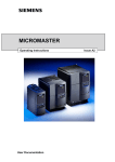
1
SIPLUS CMS4000 ION SIMATIC S7-400 T001 – Manual SIPLUS CMS Preface 1 Scope of Delivery 2 Introducing the Product 3 Block Description 4 Installation 5 Engineering in AWL 6 Tips and Tricks 7 References 8 Contact Information 9 SIPLUS CMS SIPLUS CMS4000 ION SIMATIC S7-400 T001 Manual English Release 2011-09 English Release 2011-09 1 / 22 SIPLUS CMS4000 ION SIMATIC S7-400 T001 – Manual SIPLUS CMS Safety Guidelines This document contains notices which you should observe to ensure your own personal safety as well as to avoid property damage. The notices referring to your personal safety are highlighted in the manual by a safety alert symbol, notices referring to property damage only have no safety alert symbol. Danger indicates an imminently hazardous situation which, if not avoided, will result in death or serious injury. Warning indicates a potentially hazardous situation which, if not avoided, could result in death or serious injury. Caution used with the safety alert symbol indicates a potentially hazardous situation which, if not avoided, may result in minor or moderate injury. Caution used without safety alert symbol indicates a potentially hazardous situation which, if not avoided, may result in property damage. Notice used without the safety alert symbol indicates a potential situation which, if not avoided, may result in an undesirable result or state. When several danger levels apply, the notices of the highest level (lower number) are always displayed. If a notice refers to personal damages with the safety alert symbol, then another notice may be added warning of property damage. Qualified Personnel The device/system may only be set up and operated in conjunction with this documentation. Only qualified personnel should be allowed to install and work on the equipment. Qualified persons are defined as persons who are authorized to commission, to earth, and to tag circuits, equipment and systems in accordance with established safety practices and standards. Intended Use Please note the following: Warning This device and its components may only be used for the applications described in the catalog or technical description, and only in connection with devices or components from other manufacturers approved or recommended by Siemens. This product can only function correctly and safely if it is transported, stored, set up and installed correctly, and operated and maintained as recommended. Trademarks All designations marked with ® are registered trademarks of Siemens AG. Other designations in this documentation might be trademarks which, if used by third parties for their purposes, might infringe upon the rights of the proprietors. Copyright Siemens AG 2011 All rights reserved. Reproduction, transmission or use of this document or its contents is not permitted without express written authority. Offenders will be liable for damages. All rights, including rights created by patent grant or registration of a utility model or design, are reserved. Disclaimer of Liability We have checked the contents of this document for agreement with the hardware and software described. Since deviations cannot be precluded entirely, we cannot guarantee full agreement. However, the data in the manual are reviewed regularly, and any necessary corrections will be included in subsequent editions. Suggestions for improvement are welcomed. Siemens AG Industry Sector P.O. Box 4848 90327 Nuremberg Germany English Release 2011-09 Siemens AG 2011 Technical data subject to change 2 / 22 SIPLUS CMS4000 ION SIMATIC S7-400 T001 – Manual SIPLUS CMS Table of Contents 1 Preface ................................................................................................................................................4 1.1 Purpose of this Document..............................................................................................................4 1.2 Basic Knowledge Required ............................................................................................................4 1.3 Validity of this Document................................................................................................................4 1.4 Terms .............................................................................................................................................4 2 Scope of Delivery ................................................................................................................................5 2.1 Scope of Delivery ...........................................................................................................................5 2.2 Unpacking and Checking ...............................................................................................................5 3 Introducing the Product .......................................................................................................................6 3.1 Introduction ....................................................................................................................................6 3.2 Hard- and Software Requirements ................................................................................................6 3.2.1 Software ....................................................................................................................................6 3.3 4 Ordering Numbers..........................................................................................................................6 Block Description.................................................................................................................................7 4.1 Function..........................................................................................................................................7 4.2 Parameters.....................................................................................................................................7 4.3 Conditions ......................................................................................................................................8 5 Installation ...........................................................................................................................................9 5.1 Automation License Manager ........................................................................................................9 5.2 Installation of Library ION SIMATIC S7-400 T001.........................................................................9 6 Engineering in AWL...........................................................................................................................10 6.1 Copying the necessary SW components .....................................................................................10 6.2 Insert New Connections ...............................................................................................................11 6.3 Calling the Function Block - Startup OBs (OB100, OB101 and OB102) .....................................14 6.4 Calling the Function Block - OB3x Cyclic Interrupts ....................................................................16 6.5 UIK ...............................................................................................................................................18 6.6 Loading Components ...................................................................................................................19 7 Tips and Tricks ..................................................................................................................................20 7.1 Reset the Function Block .............................................................................................................20 7.2 Engineering during Runtime ........................................................................................................20 7.3 Changing the Number of the Function Block ...............................................................................20 7.4 Analyzing of Connection-Problems..............................................................................................20 7.5 Multi-Instancing of ION SIMATIC S7-400 T001...........................................................................20 8 References ........................................................................................................................................21 8.1 9 Other Documentation ...................................................................................................................21 Contact Information ...........................................................................................................................22 English Release 2011-09 3 / 22 SIPLUS CMS4000 ION SIMATIC S7-400 T001 – Manual 1 SIPLUS CMS Preface 1.1 Purpose of this Document This document supports you when commissioning and using the software SIPLUS CMS4000 ION SIMATIC S7-400 T001 of the SIPLUS CMS4000 product line. 1.2 Basic Knowledge Required In order to understand this manual, general knowledge of automation technology and software packages SIPLUS CMS4000 X-Tools, STEP 7, S7-SCL, S7-CFC is required. In addition, you must be familiar with network technology (UDP/IP) and with using computers with MS Windows XP. 1.3 Validity of this Document This document is valid for the following software: ● SIPLUS CMS4000 ION SIMATIC S7-400 T001, V 03.00 to V 03.06 During the following pages, this software will be referred to by the term ION SIMATIC S7-400 T001. 1.4 Terms The following terms are used within this document: Definition Description CP Communication Processor DB Data Block FB Function Block ION I/O-Node OB Organization Block UIK Universal Identification Key SW Software English Release 2011-09 4 / 22 SIPLUS CMS4000 ION SIMATIC S7-400 T001 – Manual 2 SIPLUS CMS Scope of Delivery 2.1 Scope of Delivery What is shipped? • CD SIPLUS CMS4000 ION SIMATIC S7-400 T001 - Software & Documentation • Certificate of License (CoL) • Storage medium with License Key 2.2 Unpacking and Checking After unpacking, please check • the packet for completeness and • all parts for transport damage. Caution Do not use any content / parts that show evidence of damage! English Release 2011-09 5 / 22 SIPLUS CMS4000 ION SIMATIC S7-400 T001 – Manual 3 SIPLUS CMS Introducing the Product Introduction 3.1 The ION SIMATIC S7-400 T001 is used in order to acquire data from a SIMATIC S7-400 controller with Ethernet CP and to transmit the recorded data via Ethernet (UDP/IP) to a superior industrial PC. After the engineering, the ION SIMATIC S7-400 T001 is used for the transmission of measurement data to SIPLUS CMS4000 X-Tools (during the following pages referred as X-Tools) which is a software package that is able to visualize, analyse and store the data. The usage of an ION SIMATIC S7-400 T001 allows transmitting up to 712 byte of data. The data is divided into 178 channels and each channel consists of 32 bit (DWORD), where several signals can be merged to a channel. The ION SIMATIC S7-400 T001 consists of a function block which must be engineered into a SIMATIC S7-400 controller with an Ethernet CP. Hard- and Software Requirements 3.2 Hardware • PC with Windows XP Professional (≥ Service Pack 2) o CPU with ≥ 1.2 GHz or multicore CPU o working memory ≥ 512 MByte (2 GByte recommended) o OpenGL enabled graphic controller (from 1024x768 Pixels, 1280x1024 Pixels or more recommended) o IEEE1394, Ethernet and USB interfaces • SIMATIC S7-400 controller with integrated Ethernet / PROFINET interface o CPU 41x with CP 443-1 (ab EX11) / CP 443-1 Advanced • Ethernet connecting cables 3.2.1 Software • SIPLUS CMS4000 X-Tools Standard or Professional (V 03.01 SP1 or higher) • STEP7 (using V 5.4 + SP2 or higher) 3.3 Ordering Numbers Article Ordering Number (MLFB) SIPLUS CMS4000 ION SIMATIC S7-400 T001 6AT8000-0CA00-1XA0 SIPLUS CMS4000 X-Tools Standard V 03.xx 6AT8000-0AB00-1BA0 SIPLUS CMS4000 X-Tools Professional V 03.xx 6AT8000-0AB00-2BA0 Further information is obtained from your local Siemens office and from the homepage http://www.siemens.com/siplus-cms. English Release 2011-09 6 / 22 SIPLUS CMS4000 ION SIMATIC S7-400 T001 – Manual 4 SIPLUS CMS Block Description 4.1 Function The ION SIMATIC S7-400 T001 is used in order to acquire data from a SIMATIC S7-400 controller with Ethernet CP and to transmit the recorded data via Ethernet (UDP/IP) to a superior industrial PC. The ION SIMATIC S7-400 T001 consists of a function block (FB) which must be engineered into a SIMATIC S7-400 controller with Ethernet CP. The communication protocol is UDP/IP. The FB is called in a cyclic interrupt (e.g. OB35) and allows transmission of up to 712 byte of data each cycle. The data is divided into 178 channels and each channel consists of 32 bit (DWORD). The channels are filled with data in the S7 program. It is possible to merge several signals into one channel (e.g. two WORD signals). The FB is called in startup OB (OB100, OB101, OB102) for initialization. Therefore the parameter COM_RST is set to TRUE. During initialization the number of active channels is written, the cycle time is set and some other calculations for service are done. Afterwards a phase begins, in which the FB runs along passive in the program. Only after announcing the X-Tools the FB is actived and it takes place data exchange with X-Tools. Details for engineering in X-Tools you can find in the X-Tools User Manual. When data transmission is started the signals are transmitted to X-Tools. Therefore the signals are buffered in two buffers. Each buffer can store 712 bytes. With 178 active channels one buffer is transmission buffer and one is the buffer for the current data. The buffers are alternating written and transmitted. If not all channels are active more cycles can be buffered. With 89 active channels each buffer can buffer two measurement cycles, the transmission is initialized after each two cycles. The communication load can be reduced. 4.2 Parameters Parameter Declaration Data type Description COM_RST INPUT BOOL With ‚True’ on this signal a reset of the FB is forced. During runtime it should be ‚False’. The FB remains in initializing routine as long as COM_RST is set to ‚True’. CYCLE_T INPUT INT Cycle time of calling alert in ms. LADDR INPUT WORD Local address of CP. This can be found in HW config. COMMAND_ID INPUT INT ID for command connection (0x0001 … 0x0FFF). DATA_ID INPUT INT ID for data connection (0x0001 … 0x0FFF). CURRENT_ CHANNELS INPUT INT Number of channels which are transmitted to X-Tools each cycle (1 … 178). CHANNEL INPUT ARRAY[0..177] Array, which defines the channels which shall be transOF DWORD mitted to X-Tools. A reading of peripherals is not possible. UIK0..UIK7 INPUT BYTE English Release 2011-09 UIK of the ION SIMATIC S7-400 T001. See 6.4 for details. 7 / 22 SIPLUS CMS4000 ION SIMATIC S7-400 T001 – Manual 4.3 SIPLUS CMS Conditions During projecting of the ION SIMATIC S7-400 T001 the conditions of all used components have to be respected. The ION SIMATIC S7-400 T001 must not be called in OB1. The minimum cycle time of the calling OB as the number of channels which can be transmitted properly in this time are specific for each project and hardly depending on SIMATIC S7-400 CPU type and network usage. The used configuration has to be checked for stability and must not operate at the limit, because in case of errors (e.g. BUS errors) a higher CPU load can be expected. The ION SIMATIC S7-400 T001 can transmit limited amount of data over the Ethernet interface. When the capacity of the interface is insufficient data is lost, in this case proper system behaviour can not be guaranteed. The internal counter “Drops1” counts the number of packets which could not be transmitted properly. It can be supervised in the Variable Table. The user has to check the compatibility of CPU and CP. The system is released for usage of one ION SIMATIC S7-400 T001 per SIMATIC CPU Notice Wrong project engineering can lead to errors or stop of the CPU. English Release 2011-09 8 / 22 SIPLUS CMS4000 ION SIMATIC S7-400 T001 – Manual 5 SIPLUS CMS Installation 5.1 Automation License Manager To use ION SIMATIC S7-400 T001 software, you require a product-specific license key (user rights). Starting with X-Tools V 03.02, this key is installed with the Automation License Manger. The Automation License Manger is a software product from Siemens AG. It is used to manage the license keys (license modules) for all systems. The Automation License Manger is located on the installation device of X-Tools starting with V 03.02. Details about installation and handling you can take from X-Tools User Manual. The license of ION SIMATIC S7-400 T001 is a floating license which is valid for an unlimited amount of time. For each started Device Profile (for each active ION SIMATIC S7-400 T001) a license key is required by XTools. The key is acquired during runtime and released when the Device Profile is stopped. More information for license management and handling of license key you can take from X-Tools User Manual 5.2 Installation of Library ION SIMATIC S7-400 T001 Insert the product-CD “ION SIMATIC S7-400 T001 - Software & Documentation” into the drive of your PC. Start the SIMATIC Manager and open via File > Retrieve... the dialog for de-archiving of projects and libraries. Choose the path to your CD-drive and open the archive file “ION SIMATIC S7-400 T001 <current version>.zip” from the product CD. Finally choose the target directory and the storage path for the ION SIMATIC S7-400 T001 library and confirm with OK. When de-archiving is finished apply the shown dialog on “Yes” to open the library. The library is installed properly. After successful installation, the engineering can begin. English Release 2011-09 9 / 22 SIPLUS CMS4000 ION SIMATIC S7-400 T001 – Manual 6 SIPLUS CMS Engineering in AWL 6.1 Copying the necessary SW components Opening of the Library If the library was not opened automatically, go to the SIMATIC Manager and choose File > Open. In the next dialog select the tab Libraries and choose the library ION SIMATIC S7-400 T001. Afterwards confirm in the dialog with the “OK” button. To copy the necessary components Copy all SW components of the ION SIMATIC S7-400 T001. The SW components FC50, FC60, FC8, SFC1, SFC6 originate from the library “Standard Library” and can be copied from this source. English Release 2011-09 10 / 22 SIPLUS CMS4000 ION SIMATIC S7-400 T001 – Manual 6.2 SIPLUS CMS Insert New Connections For the communication with X-Tools two connections of type unspecified UDP-Connection are used, the command- and the data-connection. Insert New Connection Open NetPro, chose the current CPU and create a new connection of type unspecified UDP connection. Edit the configuration according to the following figure. The ID (Hex) can be chosen free. It must be entered in the function call. The ID and the local address (LADDR) you need for function call later on. English Release 2011-09 11 / 22 SIPLUS CMS4000 ION SIMATIC S7-400 T001 – Manual SIPLUS CMS Change to the addresses and configure the port according to the following image. The port number can be chosen free. It must me entered in the X-Tools configuration. Take care that the address assignment is done in the block. Set the according marker. Close the dialog via “OK” and create another connection according to the following figure. Select the ID for the data connection. The local address is equal to the local address of the command connection. Set a proper port and set the marker for the address assignment at block. English Release 2011-09 12 / 22 SIPLUS CMS4000 ION SIMATIC S7-400 T001 – Manual SIPLUS CMS Note the current configuration. For the projecting the local endpoint of the CP (here: LADDR = W#16#0FFD) and the connection IDs (here: command = 1 and data = 2) are needed. Store and compile the configuration and load the connections into your PLC PLC -> Download to Current Project -> Connections and Gateways. English Release 2011-09 13 / 22 SIPLUS CMS4000 ION SIMATIC S7-400 T001 – Manual 6.3 SIPLUS CMS Calling the Function Block - Startup OBs (OB100, OB101 and OB102) Description The component ION SIMATIC S7 -400 T001 must be connected in the Startup OBs, to allow a system restart when the CPU initiates the restart. The following table shows the available Startup OB types: Type of Startup Corresponding OB Hot restart OB 101 Warm restart OB 100 Cold restart OB 102 Check which Startup OBs are used by your CPU and which Startup OBs your application needs for proper initialization in all states. Maybe you need to implement more than one Startup OB. In the following part the implementation of OB100 is shown as example. Function Block call If the OB100 is not available jet you must insert it into your program. For this, right Mouse click on the component folder and select Insert new Object > Organization Block. Open the OB100 via a double click and add a call of FB1. The assigned instance database can be freely selected (select any free number, in the example DB1). Afterwards confirm in the dialog with the “Yes” button and the DB is automatically generated by the SIMATIC manager. Calling FB1 in the OB100 English Release 2011-09 14 / 22 SIPLUS CMS4000 ION SIMATIC S7-400 T001 – Manual SIPLUS CMS Now you must set the parameter COM_RST with TRUE to initialize the ION SIMATIC S7-400 T001. Afterwards save and close the component. Initialized parameter list of the ION SIMATIC S7-400 T001 in the OB100 English Release 2011-09 15 / 22 SIPLUS CMS4000 ION SIMATIC S7-400 T001 – Manual 6.4 SIPLUS CMS Calling the Function Block - OB3x Cyclic Interrupts Description The acquisition and transmission of measurement data is done via a function call in a cyclic interrupt (OB3x). The sample time matches the cycle time of this OB. It can be configured in HW Config. It is recommended to use a cycle time about 100 ms, it must not be above 300 ms. Write data into the Transmission Channel Insert new cyclic interrupt-OB into your program, or work on an existing one in your program. In the following example OB35 is used. The channels which can be observed will be supplied. There exists of up to 178 channels each having 4 bytes per channel for a total of 712 bytes. The channels up to 178 are sent cyclically to the PC via the X-Tools once connected with the ION SIMATIC S7-400 T001. The current measuring data is determined by the configuration of these up to 178 channels. For the beginning you must fill the data block. Therefore you have two options: a) Load the data and transfer it directly into the destination channel in the DB. The editor produces the database addresses automatically via input of the channel numbering in the format “DB1.CHANNEL [index]. b) All data can be written into an array which can be set to the input CHANNEL of the FB1 during block call. Provisioning for Channel English Release 2011-09 16 / 22 SIPLUS CMS4000 ION SIMATIC S7-400 T001 – Manual SIPLUS CMS Write data into the Transmission Channel When the channels are filled with data you can add an additional network an project you ION SIMATIC S7-400 T001 as follows: Component call in the OB35 In the cyclic interrupt COM_RST must be set to FALSE during runtime of the block. Enter for the parameter CYCLE_T the temporary component variable OB3x_EXC_FREQ. This setting defines the cycle time of the interrupt OB3x. For the communication you need to specify connection IDs and the local CP address. Enter for the parameter COMMAND_ID a connection ID for the command connection (0x0001…0x0FFF) and for the parameter DATA_ID a connection ID for the data link (0x0001…0x0FFF). These IDs were specified during creation of the connections. Enter the local CP address for LADDR. Enter for the parameter CURRENT_CHANNELS the channels to be transmitted per cycle (1…178). Attention, also empty channels are transmitted. For the parameter CHANNEL it is optional to enter a field which contains the measurement data. This is valid only for 16 channels. For the last inputs you have to configure the UIK of the ION SIMATIC S7-400 T001. Regard the following chapter for details. English Release 2011-09 17 / 22 SIPLUS CMS4000 ION SIMATIC S7-400 T001 – Manual 6.5 SIPLUS CMS UIK Description Each ION SIMATIC S7-400 T001 must possess a system wide defined number, the UIK. The UIK is used by the X-Tools for the clear identification of the ION SIMATIC S7-400 T001. The device name, which is shown by default in X-Tools, consists of the device type and the UIK. Example: ION SIMATIC S7-400 T001 (000008-00-06010000). Assigning the UIK It is formed under normal conditions via 2 zero bytes and the MAC address of the hardware. Entering the parameters UIK0 and UIK1 contain a zero byte (B#16#0) in each case. Enter from UIK2 byte wise the MAC address (must be in hexadecimal representation). In the following example the MAC address 08-0006-01-00-00 is used. Null Bytes MAC Adresse Assignment of the UIK If multiple ION SIMATIC S7-400 T001 are to be operated on a single hardware unit (over one IP-address), it must be ensured that the UIK is individual. Use in addition the first two bytes (UIK0 and UIK1) as example for a sequential numbering of the blocks - must be in hexadecimal representation - as a defined entry for a clear UIK. English Release 2011-09 18 / 22 SIPLUS CMS4000 ION SIMATIC S7-400 T001 – Manual 6.6 SIPLUS CMS Loading Components When you have finished you implementation mark / highlight all blocks of your project. Then select in the menu PLC > Download or click on the appropriate symbol to load the marked / highlighted components into the CPU. Then the CPU must be restarted (STOP RUN) to initialize the ION SIMATIC S7-400 T001. Now the connection to X-Tools can be initiated. English Release 2011-09 19 / 22 SIPLUS CMS4000 ION SIMATIC S7-400 T001 – Manual 7 SIPLUS CMS Tips and Tricks 7.1 Reset the Function Block The ION SIMATIC S7-400 T001 can be reset by COM_RST. This input can be connected to a bit memory which makes it possible to reset the ION SIMATIC S7-400 T001 at any moment easily. 7.2 Engineering during Runtime Because of the possibility to initialize the ION SIMATIC S7-400 T001 via input COM_RST you can add it to you project during runtime. It is no STOP RUN of the CPU necessary. 7.3 Changing the Number of the Function Block The number of ION SIMATIC S7-400 T001 (FB1) can be changed user-defined. It is just necessary to adapt the Symbol Table. It is possible to change the numbers of FC50/FC60 by STEP 7 option “Rewire”. When you plan to rewire the blocks it is recommended to do this in an empty project and add just the rewired blocks into you working project. 7.4 Analyzing of Connection-Problems If the interface is not able to transmit all data (OB-cycle to fast or communication too high) the variable “Dummy1” in the corresponding DB is rising. This can be supervised by variable table or it can be transmitted to X-Tools via the ION SIMATIC S7-400 T001. 7.5 Multi-Instancing of ION SIMATIC S7-400 T001 It is possible to call multiple instances of the ION SIMATIC S7-400 T001 in one SIMATIC CPU. This is necessary when the required amount of data is more than 712 Byte per cycle. Each instance of the ION SIMATIC S7-400 T001 must be called in OB100 with COM_RST = TRUE to initialize the FB. For each instance a separate data block and a dedicated connection pair (command and data connection) is required. The UIK must be unique for each ION SIMATIC S7-400 T001. The bytes UIK2...UIK7 shall be set to the MAC address of the used Ethernet interface. To keep unique UIKs for each ION SIMATIC S7-400 T001 in the bytes UIK0 and UIK1 can be numbered sequential. The number of usable instances is limited by capacity of CPU. If multiple instances are called in one controller the memory usage and cycle time of the CPU have to be checked. Each active ION SIMATIC S7-400 T001 needs a softare licence key. English Release 2011-09 20 / 22 SIPLUS CMS4000 ION SIMATIC S7-400 T001 – Manual 8 SIPLUS CMS References 8.1 Other Documentation • Manual: SIPLUS CMS4000 X-Tools User Manual • Reference Manual: SIMATIC System Software for S7-300/400 Systen and Standard Functions • Manual: SIMATIC Programming with STEP 7 • http://www.siemens.com/siplus-cms English Release 2011-09 21 / 22 SIPLUS CMS4000 ION SIMATIC S7-400 T001 – Manual 9 SIPLUS CMS Contact Information Adress SIEMENS AG I IA CE DE WUERZBURGER STR. 121 90766 FUERTH GERMANY Internet http://www.siemens.com/siplus-cms English Release 2011-09 22 / 22