1
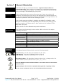
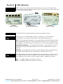
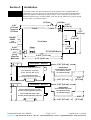
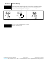
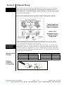
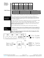
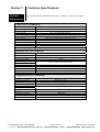
Amphenol
RJ-Switch
Industrial Ethernet
Unmanaged Switch
- User Manual Contents
Section 1
General Information
Page 3
Section 2
LED Indicators
Page 4
Section 3
Installation
Page 5
Section 4
Power Wiring
Page 6
Section 5
Ethernet Wiring
Page 7
Section 6
Switching Features
Page 9
Section 7
Technical Specifications
Page 11
Section 8
Service Information
Page 13
Applicable standards and certifications:
Total Quality
Hazardous Locations
Standard Locations
European Directives
Marine & Offshore
US Emissions
This manual applies to the following products:
•
RJS-5ES Series – Unmanaged Ethernet switch with 5 ports 10/100 Mbps
•
RJS-9ES Series – Unmanaged Ethernet switch with 9 ports 10/100 Mbps
Unmanaged Switch User Manual
Page 1 of 13
Last Revised: 11-Jul-06
Amphenol – 948, Promenade de l‘Arve – B.P. 29 – 74311 THYEZ Cedex – France - +33(0)4.50.89.28.00 – www.rjswitch.com
Amphenol Statement of Limited Warranty:
The characteristics of the Products shall be defined as those published in the most recent version of the Vendor's specifications,
unless different characteristics are expressly agreed between the Vendor and the Customer.
Unless expressly agreed to the contrary, the guarantee shall be valid for one year from the date of delivery.
The guarantee shall be made invalid:
• Where the components have been damaged in transit or have not been stored by the Customer in conditions in accordance
with the specification.
• Where the components have been subjected to abuse (mechanical, electrical or thermal) on installation or on use and, in
the case of slices/dice, have been subjected to handing or such operations as the welding of connecting wires mounting by
soldering or sticking.
• Where the unfitness or defectiveness of the components has resulted from exceeding the maximum values for usage
(temperature limit, maximum voltage, etc.) as defined by the Vendor, or from incorrect choice of application.
Furthermore, the guarantee shall not cover consequential liability, direct or indirect which may result from the failure of a
component supplied by the Vendor.
The foregoing constitutes the Vendor's guarantee in its entirely and takes the place of any other format guarantee, implied or
otherwise.
The guarantee is limited, at the Vendor's option, to either the replacement or the repair of the component accepted by him as being
defective, to the exclusion of any other from of compensations.
INSTALLATION AND HAZARDOUS AREA WARNINGS:
These products should not be used to replace proper safety interlocking. No software-based device (or any other solid-state
device) should ever be designed to be responsible for the maintenance of consequential equipment or personnel safety. In
particular, Amphenol disclaims any responsibility for damages, either direct or consequential, that result from the use of this
equipment in any application.
All power, input and output (I/O) wiring must be in accordance with Class I, Division 2 wiring methods and in accordance with the
authority having jurisdiction.
WARNING (EXPLOSION HAZARD) -
SUBSTITUTION OF COMPONENTS MAY IMPAIR SUITABILITY FOR
CLASS 1, DIVISION 2.
WARNING (EXPLOSION HAZARD) -
WHEN IN HAZARDOUS LOCATIONS, DISCONNECT POWER BEFORE
REPLACING OR WIRING UNITS.
WARNING (EXPLOSION HAZARD) -
DO NOT DISCONNECT EQUIPMENT UNLESS POWER HAS BEEN
SWITCHED OFF OR THE AREA IS KNOWN TO BE NONHAZARDOUS.
FCC Statement:
This equipment has been tested and found to comply with the limits for a Class B digital device, pursuant to Part 15 of the FCC
Rules. These limits are designed to provide reasonable protection against harmful interference in a residential installation. This
equipment generates, uses and can radiate radio frequency energy and, if not installed and used in accordance with the instructions,
may cause harmful interference to radio communications. However, there is no guarantee that interference will not occur in a
particular installation. If this equipment does cause harmful interference to radio or television reception, which can be determined
by turning the equipment off and on, the user is encouraged to try to correct the interference by one or more of the following
measures: Reorient or relocate the receiving antenna; Increase the separation between the equipment and receiver; Connect the
equipment into an outlet on a circuit different from that to which the receiver is connected; Consult the dealer or an experienced
radio/TV technician for help.
Copyright & Trademarks:
Copyright © Amphenol, All Rights Reserved.
Note: All information in this document is subject to change without notice.
Unmanaged Switch User Manual
Page 2 of 13
Last Revised: 11-Jul-06
Amphenol – 948, Promenade de l‘Arve – B.P. 29 – 74311 THYEZ Cedex – France - +33(0)4.50.89.28.00 – www.rjswitch.com
Section 1
Overview
Operation
General Information
This manual will help you install and maintain the Amphenol Industrial Ethernet
Unmanaged switches. These products are extremely easy to install and operate because
little or no user configuration is required. Once the Ethernet connections are made and the
unit is powered up it will immediately begin to operate.
Unlike an Ethernet hub that broadcasts all messages out all ports, these witches will
intelligently route Ethernet messages only out the appropriate port. The major benefits of
this are increased bandwidth and speed, reduction or elimination of message collisions, and
deterministic performance when tied with Unmanaged systems.
These switches support both 10BaseT (10 Mbps) and 100BaseTx (100 Mbps) on their
RJ45 ports. Each of these ports will independently auto-sense the speed, allowing you to
interface to regular or fast Ethernet devices. Some models also have 100BaseFX (100
Mbps) fiber optic port(s).
Refer to Section 6 for more information on operation and features.
Performance
Specifications
Standards
and Safety
These general specifications apply to these switches. Refer to Section 7 for complete
technical specifications.
Ports (models vary)
10/100BaseT(x) (Shielded RJ45), 100BaseFX (SC or ST connectors)
Required Voltage
10 - 30 VDC (see Section 7 for power consumption for each model)
Ethernet Standards
IEEE 802.3 (10BaseT), 802.3u (100BaseTX), 802.3x (Full Duplex)
Ethernet Protocols
All standard IEEE 802.3 protocols supported
Speed Per Port
RJ45: 10 Mbps (half duplex) or 200 Mbps (full duplex)
Fiber: 100 Mbps (half duplex) or 200 Mbps (full duplex)
Ethernet Isolation
1500 Volts RMS (for 1 minute)
Operating Temp.
-40 to 85 °C
Humidity
5 to 95% (non-condensing)
Screw Terminals
14 AWG max. (tighten to 3.48 in-lbs. max.)
The Amphenol Industrial Ethernet Switch meets the following standards:
Electrical safety - UL 508, CSA C22/14; EN61010-1 (IEC1010)
EMI emissions - FCC part 15, ICES 003, EN55022; Class B
EMC immunity – EN61326-1 (EN61000-4--2, 3, 4, 5 and 6)
Hazardous locations – UL 1604, CSA C22.2/213 (Class 1, Div. 2), Groups A, B, C, D;
Cenelec EN50021 (Zone 2) EEx nA II T4 X (-40°C ≤ Ta ≤ +85°C)
Install the Amphenol Industrial Ethernet Switch in accordance with local and national
electrical codes.
Lightning Danger: Do not work on equipment during periods of lightning activity.
Do not connect a telephone line into one of the Ethernet RJ45 connectors.
Unmanaged Switch User Manual
Page 3 of 13
Last Revised: 11-Jul-06
Amphenol – 948, Promenade de l‘Arve – B.P. 29 – 74311 THYEZ Cedex – France - +33(0)4.50.89.28.00 – www.rjswitch.com
Section 2
Overview
LED Indicators
These switches have communication LEDs for each port and a power LED. Refer to the
pictures below for the typical location of these LEDs. The exact location of these LEDs may
vary between the different models.
RJS-5ES-1
(5 port – all RJ45)
Power LED
ACT / LNK
LEDs
RJS-5ES-2 or -3
( 5 ports including 1 fiber)
RJS-9ES-1
(9 ports – all RJ45)
This LED will be on solid when proper power has been applied to the unit.
The activity (ACT) and link (LNK) indication is combined into one LED (labeled
“ACT/LNK” or “A”) on these switches. There is one of these LEDs per port.
OFF – This would indicate that there is not a proper Ethernet connection (Link) between the
port and another Ethernet device. Make sure the proper cable type is in use and that it has
been plugged securely into the ports at both ends. See section 5 for proper Ethernet cabling.
ON Solid (not flashing) – This would indicate that there is a proper Ethernet connection
(Link) between the port and another Ethernet device, but no communications activity is
detected.
Flashing – This would indicate that there is a proper Ethernet connection (Link) between
the port and another Ethernet device, and that there is communications activity.
10 / 100
LEDs
This LED indicates what speed of communications is detected on the port. There is one of
these LEDs per RJ45 port and it is labeled “S”. (The fiber optic port does not have one of
these LEDs because its speed is fixed at 100 Mbps.) (Mbps = Megabits per Second)
OFF – A 10 Mbps (10BaseT) connection is detected.
ON – A 100 Mbps (100BaseTx) connection is detected.
Unmanaged Switch User Manual
Page 4 of 13
Last Revised: 11-Jul-06
Amphenol – 948, Promenade de l‘Arve – B.P. 29 – 74311 THYEZ Cedex – France - +33(0)4.50.89.28.00 – www.rjswitch.com
Section 3
Installation
All switches share the same footprint and can be snapped onto a standard DIN rail
(EN50022) or screwed directly to a flat panel. Refer to the mechanical drawing below.
Note: The Ethernet connections for the ET-5ES-1 come out the face of the unit. The
Ethernet connections for all other models come out the top. Make sure to allow enough
room to route your Ethernet cables.
Overview
ST Fiber
0.40"
[1.02 cm]
(max. for
ST Fiber)
8 or 9
Copper Ports
(RJ45)
SC Fiber
0.275"
[0.70 cm]
0 or 1
Fiber Port
(SC or ST)
3.17"
[8.05 cm]
2.935"
[7.45 cm]
DIN EN
50022
(not
included)
Front View
0.235"
[0.60 cm]
ET-GT-9ES Series
0.17"
[0.43]
(clear for
#8 screw)
B
1.60"
[4.07 cm]
Power
4.475" [11.37 cm]
4.75" [12.07 cm]
5 Port
Model – Side View
Side
View
5 port model with no fiber:
A=1.20" [3.05 cm]; B=0.55" [1.40 cm]
DIN EN50022
(not included with units;
not shown to scale;
for reference only)
5 port model with single fiber:
A=1.20" [3.05 cm]; B=0" [0 cm]
A
1.38" [3.5 cm]
5 port model with dual fiber:
A=1.95" [4.95 cm]; B=0.35" [0.90 cm]
1.06" [2.7 cm]
B
A
1.38" [3.5 cm]
9 Port
Model – Side View
Side
View
Version 1.## units (prior to 11/04):
A=1.65" [4.19 cm]; B=0.85" [2.16 cm]
0.30"
[0.76 cm]
DIN EN50022
(not included with units;
not shown to scale;
for reference only)
Version 2.## units (after 11/04):
A=1.95" [4.95 cm]; B=0.35" [0.90 cm]
1.06" [2.7 cm]
Unmanaged Switch User Manual
Page 5 of 13
0.30"
[0.76 cm]
Last Revised: 11-Jul-06
Amphenol – 948, Promenade de l‘Arve – B.P. 29 – 74311 THYEZ Cedex – France - +33(0)4.50.89.28.00 – www.rjswitch.com
Section 4
Power Wiring
These switches can be powered from the same DC source that is used to power your I/O
devices. 10 to 30 VDC needs to be applied to terminals 2 and 3. Optionally, on the 5ES
models a backup power supply may be connected. Refer to the wiring diagram below.
Terminal 1 should be tied to panel or chassis ground.
Overview
Redundant DC Power
Single DC Power
P1
P2
P1
To
Panel
P2
+
+ -
To
Panel
+ -
To
Panel
+ -
VDC Supply
+ VDC Supply
VDC Supplies
Single or Dual Power Inputs for 5ES Model
Screw Torque
DC Power
Single Power Input for 9ES Model
The screw terminals should be tightened as follows:
Maximum 3.48 in-lbs (0.4 Nm)
Unmanaged Switch User Manual
Page 6 of 13
Last Revised: 11-Jul-06
Amphenol – 948, Promenade de l‘Arve – B.P. 29 – 74311 THYEZ Cedex – France - +33(0)4.50.89.28.00 – www.rjswitch.com
Section 5
Overview
Ethernet Wiring
These switches provide connections to Ethernet devices on the factory floor. Typically a
port is used to connect to another Ethernet switch or hub that is connected to the main
Ethernet backbone. The other Ethernet ports are then connected to Ethernet devices such as
PLCs, Ethernet I/O, or industrial computers. Electrical isolation is provided on the Ethernet
ports for increased reliability.
Please follow normal Ethernet wiring practices when installing these switches.
Typical Amphenol
Industrial Ethernet
Switch Installation
Refer to the
Amphenol On-line
Catalog for More
Usage Ideas
Note: All 5 ports on the 5-port switch and ports 1-8 on the 9-port switch support auto-speed & duplex
detection, auto-mdi/mdix-corssover and auto-polarity. Port 9 is an uplink port and will auto-speed and
crossover detect but require full duplex and the correct polarity.
RJ45 Wiring
Guidelines
Ethernet Cable
Pin-outs
Use data-quality (not voice-quality) twisted pair cable rated category 5 (or better) with
standard RJ45 connectors. For best performance use shielded cable. Please note that these
cables are available as straight-thru or cross-over configurations. Either type can be used
because these switches support auto-mdi/mdix-crossover. For reference, the pin-outs of the
two cable types are listed below.
Straight-thru Cable Wiring
Pin 1
Pin 1
Pin 2
Pin 2
Pin 3
Pin 3
Pin 6
Pin 6
Cross-over Cable Wiring
Pin 1
Pin 3
Pin 2
Pin 6
Pin 3
Pin 1
Pin 6
Pin 2
Ethernet
Connector
Pin Positions
Unmanaged Switch User Manual
Page 7 of 13
Last Revised: 11-Jul-06
Amphenol – 948, Promenade de l‘Arve – B.P. 29 – 74311 THYEZ Cedex – France - +33(0)4.50.89.28.00 – www.rjswitch.com
Ethernet
Connector
Pin-outs
Cable Distance
Pin
#
MDI-X
Port
1
2
3
6
TX+
TXRX+
RX-
MDI Port
(typical for
uplink)
RX+
RXTX+
TX-
AutoMDI/
MDI-X
TX/RX+
TX/RXRX/TX+
RX/TX-
Ethernet
Device
Port
RX+
RXTX+
TX-
The maximum cable length for 10/100BaseT(x) is typically 100 meters (328 ft.).
From
Switch
Switch or Hub
To
Switch or Hub
PLC, Ethernet I/O, PC, etc.
Maximum Distance
100 meters (328 feet)
100 meters (328 feet)
Note: Hubs and switches are different devices. Hubs simply broadcast all messages
out all ports. switches intelligently route messages only out the appropriate port
Ethernet
Fiber Wiring
Guidelines
These switches may have one or two pair of fiber ports of the type multimode or
singlemode. Multimode ports support a maximum segment length of 2 km. Singlemode
ports support a maximum segment length of 15 km, 40 km (long haul models) or even
more (contact Amphenol.)
Each fiber optic port on the switch is comprised of a pair of SC or ST connectors, which
are labeled with “RX” and “TX” on the switch. When making your fiber optic
connections, make sure that the transmit (TX) port of the switch connects to the receive
(RX) port of the other device, and the receive (RX) port of the switch connects to the
transmit (TX) port of the other device.
The ACT/LNK LED will be ON solid when you have made a proper connection.
Full or Half
Duplex
Operation
The RJ45 ports will auto-sense for Full or Half duplex operation. No user configuration
is necessary. Each fiber optic port has a movable slide-switch or jumper that allows you
to select the mode. The metal cover needs to be removed to access the movable jumper.
See diagram below.
Note: You must cycle power to the switch after changing the slideswitch or jumper position.
Unmanaged Switch User Manual
Page 8 of 13
Last Revised: 11-Jul-06
Amphenol – 948, Promenade de l‘Arve – B.P. 29 – 74311 THYEZ Cedex – France - +33(0)4.50.89.28.00 – www.rjswitch.com
Section 6
Switching
Features
Switching Features
Here’s a brief explanation of some of the features found in these switches documented by
this manual.
10BaseT and 100BaseTx Auto-detection
Standard Ethernet (10BaseT) has a maximum speed of 10 Mbps in half duplex mode. Fast
Ethernet (100BaseTx) has a maximum speed of 200 Mbps in full duplex mode. The RJ45
ports on these switches automatically select the appropriate speed.
100BaseFX (multimode and singlemode) fiber optic port
The fiber optic port found on some models is classified as 100BaseFX and supports 100
Mbps operation only. Both multimode and singlemode models are available. Multimode
allows for multiple wavelengths over a cable with a core diameter of typically 50 or 62.5
microns. The maximum distance for multimode is 2 km. Singlemode uses a single
wavelength and cable core diameter of around 10 microns which allows for a maximum
distance of 15 km, 40 km or more (contact Amphenol for longer distances).
3.2 Gbps combined bandwidth
With full duplex and 100BaseTX or 100BaseFX communications, each port can provide a
full 200 Mbps of data throughput.
1K MAC addresses with automatic learning, aging and migration
Each Ethernet device inserts its unique “MAC” address into each message it sends out. The
port on the switch used for a given MAC address is automatically learned when a frame is
received from that address. Once an address is learned, the switch will route messages to
only the appropriate port, instead of broadcasting messages out all ports like a hub. A time
stamp is also placed in memory when a new address is learned. This time stamp is used
with the aging feature, which will remove unused MAC addresses from the table after 300
seconds. If a device moves, the associated port on the switch will be changed (migrated) as
needed. Up to 1,024 MAC addresses can be stored and monitored at any time.
Auto-crossover (auto-mdi/mdi-x)
The RJ45 ports will automatically detect the cable type (straight-thru vs. cross-wired) and
re-configure themselves accordingly.
Auto-polarity
The RJ45 ports (except port 9) will automatically correct for reversed polarity on the TD
and RD pair.
Auto-sensing or auto-negotiating speed
The RJ45 ports of these switches will auto-negotiate with the connected device to
determine the optimal speed (10 Mbps vs. 100 Mbps).
Automatic power saving
If there is no cable on a port, most of the circuitry for that port is disabled to save power.
Back pressure for half-duplex
The Amphenol Industrial Ethernet Switch will apply “back pressure” when necessary with
half-duplex operation. This “back pressure” will reduce congestion on busy networks.
Buffering
SRAM is used for buffering the messages. The 5ES switches have ½ Mbits (64 Kbytes)
while the 9ES switches have 1 Mbits (128 Kbytes). The buffer size is automatically
allocated for each port as necessary.
Unmanaged Switch User Manual
Page 9 of 13
Last Revised: 11-Jul-06
Amphenol – 948, Promenade de l‘Arve – B.P. 29 – 74311 THYEZ Cedex – France - +33(0)4.50.89.28.00 – www.rjswitch.com
Unmanaged operation
These switches require no supervisory processor to operate properly.
Flow control
These switches automatically support flow control frames on both the transmit and receive
sides. Back-pressure flow control for half-duplex ports and pause-frame flow control for
full-duplex ports.
Forwarding
These switches support store and forward mode. They will forward messages with known
addresses out only the appropriate port. Messages with unknown addresses, broadcast
messages, and multicast messages will get forwarded out all ports except the source port.
Full / Half duplex operation
The RJ45 ports (except port 9, which is full duplex only) of these switches support both full
and half duplex flow control. The fiber optic port(s) has a settable jumper or switch, which
allows you to select the desired operation.
Illegal frames
Illegal frames as defined by IEEE 802.3 will be dropped. This includes short frames, long
frames, CRC error frames and alignment error frames.
IEEE 802.3 compliant
The Amphenol Industrial Ethernet Switch strictly abides to the IEEE 802.3 standard for
10BaseT, 100BaseTX, and 100BaseFX Ethernet communications.
Latency
The typical latency of a message at 100 Mbps is 5 microseconds or faster. The latency is
the time it takes a message to be routed internal to a switch from one port to another.
Non-blocking
This means that the switches offer the best in performance and are capability of full-wire
speed transmissions.
Plug and play
This means that most functions or features of these switches are automatic and that there
are minimal or no optional parameters that need to be set. Just plug in your Ethernet cables,
apply power, and the unit will immediately begin to operate.
Protocol independent
These switches will work with all popular Ethernet protocols and networks such as TCP/IP,
the Internet (IP), UDP, NetBEUI, and many more. It is compatible with all protocols that run
over standard Ethernet (IEEE 802.3). In fact, it will support packets of different protocols
simultaneously.
Unmanaged Switch User Manual
Page 10 of 13
Last Revised: 11-Jul-06
Amphenol – 948, Promenade de l‘Arve – B.P. 29 – 74311 THYEZ Cedex – France - +33(0)4.50.89.28.00 – www.rjswitch.com
Section 7
Technical
Technical Specifications
Here are the technical specifications for these switches covered by this manual.
Specifications
Copper Ports: (10/100BaseTx)
10/100BaseT(x) ports
Protocols supported
Ethernet compliancy
Auto-crossover
Auto-negotiating
Auto-polarity
Flow control
Ethernet isolation
Plug and play
Cable requirements
Max. cable distance
Shielded RJ45
All standard IEEE 802.3
IEEE 802.3, 802.3u, 802.3x
Yes , Auto-mdi/mdix-crossover
10BaseT or 100BaseTX
Yes (except port 9)
Half or full duplex (port 9 is full duplex only)
1500 VRMS 1 minute
Yes
Twisted pair (Cat. 5 or better) (shielded recommended)
100 meters
Multimode Fiber Port: (100BaseFX)
Fiber port mode
Fiber port connector
Optimal fiber cable
Center wavelength
TX output power
RX input sensitivity
Maximum distance
Half and full duplex
Ethernet compliance
Eye safety
Multimode
Duplex SC or ST
50/125, 62.5/125 µm
1300 nm
Contact Amphenol for optical details.
4 km (see web or details)
Switch or jumper selectable
100BaseFX
IEC 60825-1, Class 1; FDA 21 CFR 1040.10 and 1040.11
Singlemode Fiber Port: (100BaseFX)
Fiber port mode
Fiber port connector
Optimal fiber cable
Center wavelength
TX output power
RX input sensitivity
Maximum distance
Half and full duplex
Ethernet compliance
Eye safety
Unmanaged Switch User Manual
Singlemode
Duplex SC or ST
9/125, 10/125 µm
1300 nm
Contact Amphenol for optical details.
20 km, 40 km (long haul models) or more (contact Amphenol)
Switch or jumper selectable
100BaseFX
IEC 60825-1, Class 1; FDA 21 CFR 1040.10 and 1040.11
Page 11 of 13
Last Revised: 11-Jul-06
Amphenol – 948, Promenade de l‘Arve – B.P. 29 – 74311 THYEZ Cedex – France - +33(0)4.50.89.28.00 – www.rjswitch.com
General:
Operation
Compliance
Latency (typical)
Memory bandwidth
MAC addresses
Address learning
Address aging
Address migration
Back pressure
Buffer memory
Buffers per port & buffer size
Illegal frames
Flow control
Unmanaged, Store and forward, non-blocking
IEEE 802.3 (10BaseT), 802.3u (100BaseTX), 802.3x (Flow Control)
5 usec (time to route a message from one port to another internal to switch)
3.2 Gbps
1K (1024)
Automatic
Remove old address after 300s
Automatic
Automatic for half-duplex
64KB (5ES models) or 128KB (9ES models)
Automatic and dynamic
Dropped per 802.3
Yes, for half and full duplex
Environmental:
Required supply voltage
Power consumption (typical);
(Max. 8 Watts)
(Note: Power consumption
varies on speed and amount of
activity of each port.)
Power saving
Max. screw terminal torque
and wire gauge
Operating temp. range
Storage temp. range
Humidity
Flammability
Electrical safety
EMI emissions
EMC immunity and surge
withstand
Vibration
Hazardous locations
Marine and offshore
Dimensions
Mounting
Unmanaged Switch User Manual
10 – 30 VDC
5ES-1: 4.0 Watts
5ES-2/3: 5.0 Watts
5ES-4/5: 6.0 Watts
9ES-1: 6.0 Watts
9ES-2/3: 7.0 Watts
Automatic
3.48 in-lbs (0.4 Nm), 14 AWG
-40 to 85 °C
-40 to 85 °C
5 to 95 % (non-condensing)
UL 94V-0 materials
UL508, CSA C22/14; EN61010-1 (IEC1010), CE
FCC part 15, ICES 003, EN55022; Class B; CE
EN61326-1 (EN61000-4-2, 3, 4, 5, 6), IEEE-472 (ANSI C37.90), CE
IEC68-2-6
UL1604, CSA C22.2/213 (Class 1, Div. 2), Cenelec EN50021 (Zone 2)
DNV tested
See mechanical diagrams
DIN rail or panel direct
Page 12 of 13
Last Revised: 11-Jul-06
Amphenol – 948, Promenade de l‘Arve – B.P. 29 – 74311 THYEZ Cedex – France - +33(0)4.50.89.28.00 – www.rjswitch.com
Section 8
Service
Information
Service Information
We sincerely hope that you never experience a problem with any Amphenol product. If you
do need service, call Amphenol at +33(0) 450 89 28 00 and ask for Applications
Engineering. A trained specialist will help you to quickly determine the source of the
problem. Many problems are easily resolved with a single phone call. If it is necessary to
return a unit to us, an RMA (Return Material Authorization) number will be given to you.
Amphenol tracks the flow of returned material with our RMA system to ensure speedy
service. You must include this RMA number on the outside of the box so that your return
can be processed immediately.
The applications engineer you are speaking with will fill out an RMA request for you. If the
unit has a serial number, we will not need detailed financial information. Otherwise, be sure
to have your original purchase order number and date purchased available.
We suggest that you give us a repair purchase order number in case the repair is not covered
under our warranty. You will not be billed if the repair is covered under warranty.
Please supply us with as many details about the problem as you can. The information you
supply will be written on the RMA form and supplied to the repair department before your
unit arrives. This helps us to provide you with the best service, in the fastest manner.
Normally, repairs are completed in two days. Sometimes difficult problems take a little
longer to solve.
We apologize for any inconvenience that the need for repair may cause you. We hope that
our rapid service meets your needs. If you have any suggestions to help us improve our
service, please give us a call. We appreciate your ideas and will respond to them.
For Your Convenience:
Please fill in the following and keep this manual with your Amphenol system for future
reference:
P.O. #:__________________ Date Purchased: ___________________
Purchased From:______________________________________________
Product
Support
To obtain support for Amphenol products:
Visit our website. http.//www.rjswitch.com
Phone: +33(0) 450 89 28 00
Fax: +33(0) 450 96 29 75
E-mail: mailto:[email protected]
Mailing Address: Amphenol, Promenade de l’Arve, B.P.29, 74311 Thyez Cedex, France
For more
information
You will find all useful information on the RJ-Switch series on the dedicated website:
http://www.rjswitch.com
Unmanaged Switch User Manual
Page 13 of 13
Last Revised: 11-Jul-06
Amphenol – 948, Promenade de l‘Arve – B.P. 29 – 74311 THYEZ Cedex – France - +33(0)4.50.89.28.00 – www.rjswitch.com
Mouser Electronics
Authorized Distributor
Click to View Pricing, Inventory, Delivery & Lifecycle Information:
Amphenol:
RJS5MS1