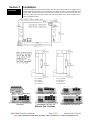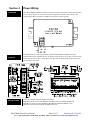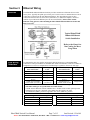
1
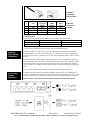
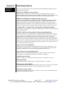
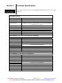
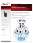
User Manual Industrial Ethernet Switches and Fiber Converter Contents at a Glance: Section 1 General Information Page 3 Section 2 LED Indicators Page 4 Section 3 Installation Page 5 Section 4 Power Wiring Page 6 Section 5 Ethernet Wiring Page 7 Section 6 Switching Features Page 9 Section 7 Technical Specifications Page 11 Section 8 Service Information Page 13 This manual applies to the following products: ET-GT-3ES-2xx or -3xx ET-GT-5ES-1, -2xx, -3xx, -4xx, or -5xx ET-GT-9ES-1, -2xx or -3xx EtherTRAK Switch User Manual Page 1 of 13 Last Revised: 15-Jul-09 Sixnet • 331 Ushers Road • Clifton Park, NY 12019 • USA • 1.518.877.5173 • mailto:[email protected] SIXNET Protected Technology Policy: Sixnet protects your investment in Sixnet systems with long-term planned technology and our unique Protected Technology Policy. We will continue to support the specified capabilities of standard Sixnet products for at least five years. We plan each product improvement and new feature to be upward compatible with existing designs and installations. Our goals are to make each new software release bring new power to your Sixnet systems and have every existing feature, applications program and data file continue to work. We protect your investment even further with a liberal five-year trade-in policy. Exchange standard products for upgraded versions of the same product to take advantage of new features and performance improvements at any time for five years. A prorated trade-in allowance will be given for your existing equipment. Sixnet protects your long-term productivity with state-of-the-art planned technology and continued support. Sixnet Statement of Limited Warranty: Sixnet LLC, manufacturer of Sixnet products, warrants to Buyer that products, except software, manufactured by Sixnet will be free from defects in material and workmanship. Sixnet' obligation under this warranty will be limited to repairing or replacing, at Sixnet' option, the defective parts within one year of the date of installation, or within 18 months of the date of shipment from the point of manufacture, whichever is sooner. Products may be returned by Buyer only after permission has been obtained from Sixnet. Buyer will prepay all freight charges to return any products to the repair facility designated by Sixnet. This limited warranty does not cover losses or damages which occur in shipment to or from Buyer or due to improper installation, maintenance, misuse, neglect or any cause other than ordinary commercial or industrial applications. In particular, Sixnet makes no warranties whatsoever with respect to implied warranties of merchantability or fitness for any particular purpose. All such warranties are hereby expressly disclaimed. No oral or written information or advice given by Sixnet or Sixnet’s representative shall create a warranty or in any way increase the scope of this warranty. This limited warranty is in lieu of all other warranties whether oral or written, expressed or implied. Sixnet's liability shall not exceed the price of the individual units, which are the basis of the claim. In no event shall Sixnet be liable for any loss of profits, loss of use of facilities or equipment, or other indirect, incidental or consequential damages. INSTALLATION AND HAZARDOUS AREA WARNINGS: These products should not be used to replace proper safety interlocking. No software-based device (or any other solid-state device) should ever be designed to be responsible for the maintenance of consequential equipment or personnel safety. In particular, Sixnet disclaims any responsibility for damages, either direct or consequential, that result from the use of this equipment in any application. All power, input and output (I/O) wiring must be in accordance with Class I, Division 2 wiring methods and in accordance with the authority having jurisdiction. WARNING (EXPLOSION HAZARD) - SUBSTITUTION OF COMPONENTS MAY IMPAIR SUITABILITY FOR CLASS 1, DIVISION 2. WARNING (EXPLOSION HAZARD) - WHEN IN HAZARDOUS LOCATIONS, DISCONNECT POWER BEFORE REPLACING OR WIRING UNITS. WARNING (EXPLOSION HAZARD) - DO NOT DISCONNECT EQUIPMENT UNLESS POWER HAS BEEN SWITCHED OFF OR THE AREA IS KNOWN TO BE NONHAZARDOUS. FCC Statement: This equipment has been tested and found to comply with the limits for a Class B digital device, pursuant to Part 15 of the FCC Rules. These limits are designed to provide reasonable protection against harmful interference in a residential installation. This equipment generates, uses and can radiate radio frequency energy and, if not installed and used in accordance with the instructions, may cause harmful interference to radio communications. However, there is no guarantee that interference will not occur in a particular installation. If this equipment does cause harmful interference to radio or television reception, which can be determined by turning the equipment off and on, the user is encouraged to try to correct the interference by one or more of the following measures: Reorient or relocate the receiving antenna; Increase the separation between the equipment and receiver; Connect the equipment into an outlet on a circuit different from that to which the receiver is connected; Consult the dealer or an experienced radio/TV technician for help. Copyright & Trademarks: Copyright Sixnet, All Rights Reserved. EtherTRAK is a registered trademark of Sixnet. Note: All information in this document is subject to change without notice. EtherTRAK Switch User Manual Page 2 of 13 Last Revised: 15-Jul-09 Sixnet • 331 Ushers Road • Clifton Park, NY 12019 • USA • 1.518.877.5173 • mailto:[email protected] Section 1 Overview General Information This manual will help you install and maintain the EtherTRAK Industrial Ethernet Switches and Fiber Converter. These products are extremely easy to install and operate because little or no user configuration is required. Once the Ethernet connections are made and the unit is powered up it will immediately begin to operate. Note: The Fiber Converter incorporates the same Layer 2 Ethernet switch technology as all the other ET-GT-#ES products. Throughout this manual, any mention of Ethernet Switches also applies to the Fiber Converter unless specifically noted otherwise. Operation Unlike an Ethernet hub that broadcasts all messages out all ports, the EtherTRAK Industrial Ethernet Switches will intelligently route Ethernet messages only out the appropriate port. The major benefits of this are increased bandwidth and speed, reduction or elimination of message collisions, and deterministic performance when tied with real-time systems. The EtherTRAK Industrial Ethernet Switches support both 10BaseT (10 Mbps) and 100BaseTx (100 Mbps) on their RJ45 ports. Each of these ports will independently auto-sense the speed, allowing you to interface to regular or fast Ethernet devices. Some models also have 100BaseFX (100 Mbps) fiber optic port(s). Refer to Section 6 for more information on Industrial Ethernet Switch operation and features. Performance Specifications These general specifications apply to the EtherTRAK Industrial Ethernet Switches. Refer to Section 7 for complete technical specifications. Ports (models vary) Required Voltage Ethernet Standards Ethernet Protocols Speed Per Port Ethernet Isolation Operating Temp. Humidity Screw Terminals Standards and Safety 10/100BaseT(x) (Shielded RJ45), 100BaseFX (SC or ST connectors) 10 - 30 VDC (see Section 7 for power consumption for each model) IEEE 802.3 (10BaseT), 802.3u (100BaseTX), 802.3x (Full Duplex) All standard IEEE 802.3 protocols supported RJ45: 10 Mbps (half duplex) or 200 Mbps (full duplex) Fiber: 100 Mbps (half duplex) or 200 Mbps (full duplex) 1500 Volts RMS (for 1 minute) -40 to 85 C 5 to 95% (non-condensing) 14 AWG max. (tighten to 3.48 in-lbs. max.) (non-removable terminals on the models ET-GT-5ES-1,-4xx,-5xx and ET-GT-9ES-xxx) 12 AWG max. (tighten to 5.3 in-lbs. max.) (removable terminals on the models ET-GT-3ES-xxx and ET-GT-5ES-2xx, -3xx) The EtherTRAK Industrial Ethernet Switch meets the following standards: Electrical safety - UL 508, CSA C22/14; EN61010-1 (IEC1010) EMI emissions - FCC part 15, ICES 003, EN55022; Class B EMC immunity – EN61326-1 (EN61000-4--2, 3, 4, 5 and 6) Hazardous locations – UL 1604, CSA C22.2/213 (Class 1, Div. 2), Groups A, B, C, D; Cenelec EN50021 (Zone 2) EEx nA II T4 X (-40°C ≤ Ta ≤ +85°C) Install the EtherTRAK Industrial Ethernet Switch in accordance with local and national electrical codes. Lightning Danger: Do not work on equipment during periods of lightning activity. Do not connect a telephone line into one of the Ethernet RJ45 connectors. EtherTRAK Switch User Manual Page 3 of 13 Last Revised: 15-Jul-09 Sixnet • 331 Ushers Road • Clifton Park, NY 12019 • USA • 1.518.877.5173 • mailto:[email protected] Section 2 Overview LED Indicators The EtherTRAK Industrial Ethernet Switches have communication LEDs for each port and a power LED. Refer to the pictures below for the typical location of these LEDs. The exact location of these LEDs may vary between the different models. ET-GT-3ES-2SC, -2ST, -3SC or -3ST ET-GT-5ES-1 ET-GT-9ES-1 ET-GT-5ES-4SC, -4ST, -5SC or -5ST ET-GT-5ES-2SC, -2ST, -3SC or -3ST ET-GT-9ES-2SC, -2ST, -3SC or -3ST Power LED This LED will be on solid when proper power has been applied to the unit. ACT / LNK LEDs The activity (ACT) and link (LNK) indication is combined into one LED (labeled “ACT/LNK” or “A”) on the EtherTRAK Industrial Ethernet Switches. There is one of these LEDs per port. OFF – This would indicate that there is not a proper Ethernet connection (Link) between the port and another Ethernet device. Make sure the proper cable type is in use and that it has been plugged securely into the ports at both ends. See section 5 for proper Ethernet cabling. ON Solid (not flashing) – This would indicate that there is a proper Ethernet connection (Link) between the port and another Ethernet device, but no communications activity is detected. Flashing - This would indicate that there is a proper Ethernet connection (Link) between the port and another Ethernet device, and that there is communications activity. 10 / 100 LEDs This LED indicates what speed of communications is detected on the port. There is one of these LEDs per RJ45 port and it is labeled “S”. (The fiber optic port does not have one of these LEDs because its speed is fixed at 100 Mbps.) (Mbps = Megabits per Second) OFF – A 10 Mbps (10BaseT) connection is detected. ON – A 100 Mbps (100BaseTx) connection is detected. EtherTRAK Switch User Manual Page 4 of 13 Last Revised: 15-Jul-09 Sixnet • 331 Ushers Road • Clifton Park, NY 12019 • USA • 1.518.877.5173 • mailto:[email protected] Section 3 Overview Installation All EtherTRAK Industrial Ethernet Switches share the same footprint and can be snapped onto a standard DIN rail (EN50022) or screwed directly to a flat panel. Refer to the mechanical drawing below. Note: The Ethernet connections for the ET-GT-5ES-1 come out the face of the unit. The Ethernet connections for all other models come out the top. Make sure to allow enough room to route your Ethernet cables. ET-GT-3ES-xxx ET-GT-5ES-1 ET-GT-5ES-2xx ET-GT-5ES-3xx ET-GT-5ES-1 ET-GT-9ES-1 ET-GT-5ES-4xx ET-GT-5ES-5xx ET-GT-9ES-1 ET-GT-9ES-xxx ET-GT-5ES-2SC, -2ST, -3SC, -3ST ET-GT-3ES-2SC, -2ST, -3SC, -3ST ET-GT-9ES-2SC, -2ST, -3SC, -3ST ET-GT-5ES-4SC, -4ST, -5SC, -5ST Ethernet Port Locations EtherTRAK Switch User Manual Page 5 of 13 Last Revised: 15-Jul-09 Sixnet • 331 Ushers Road • Clifton Park, NY 12019 • USA • 1.518.877.5173 • mailto:[email protected] Section 4 Power Wiring Overview EtherTRAK Industrial Ethernet Switches can be powered from the same DC source that is used to power your I/O devices. 10 to 30 VDC needs to be applied to terminals 2 and 3. Refer to the wiring diagram below. Terminal 1 should be tied to panel or chassis ground. RM-PS-024-01N (optional) The RM-PS-024-01 can be used to power your EtherTRAK Industrial Ethernet Switches, instrumentation loops, and other devices. It operates on 85-264 VAC (47-63 Hz) or 120-370 VDC and outputs 24 VDC at up to 1 Amp. Refer to its data sheet for details. Refer to the figure below for the power connections. Screw Torque The screw terminals should be tightened as follows: Maximum 3.48 in-lbs (0.4 Nm) (models ET-GT-5ES-1,-4xx,-5xx and ET-GT-9ES-xxx) Maximum 5.3 in-lbs (0.6 Nm) (models ET-GT-3ES-xxx and ET-GT-5ES-2xx, -3xx) Maximum 3.48 in-lbs (0.4 Nm)(for the RM-PS-024-01F) EtherTRAK Switch User Manual Page 6 of 13 Last Revised: 15-Jul-09 Sixnet • 331 Ushers Road • Clifton Park, NY 12019 • USA • 1.518.877.5173 • mailto:[email protected] Section 5 Overview Ethernet Wiring The EtherTRAK Industrial Ethernet Switches provides connections to Ethernet devices on the factory floor. Typically the uplink port or fiber port is used to connect to another Ethernet switch or hub that is connected to the main Ethernet backbone. The other Ethernet ports are then connected to Ethernet devices such as PLCs, Ethernet I/O, or industrial computers. Electrical isolation is provided on the Ethernet ports for increased reliability. Please follow normal Ethernet wiring practices when installing the EtherTRAK Industrial Ethernet Switch and Fiber Converter. Typical EtherTRAK Industrial Ethernet Switch Installation Refer to the Sixnet Online Catalog for More Usage Ideas RJ45 Wiring Guidelines Use data-quality (not voice-quality) twisted pair cable rated category 5 with standard RJ45 connectors. For best performance use shielded cable. Please note that these cables are available as straight-thru or cross-over configurations. The following is a guide for when to use each type: STANDARD (MDI-X) * Cable Type * UPLINK (MDI) * Cable Type * Port connected to to Use Port connected to to Use PC card Straight-thru PC card Cross-over Ethernet I/O Straight-thru Ethernet I/O Cross-over PLC Straight-thru PLC Cross-over Other Ethernet enabled Straight-thru Other Ethernet enabled Cross-over devices devices Straight-thru Standard port on Uplink port on another Straight-thru (see note 2) switch or hub (see note 2) another switch or hub * Note 1: Most Sixnet switches have auto-mdi/mdi-x (auto-crossover) ports that will work with either cable type. See specifications for which models. ** Note 2: Some Ethernet switches and hubs have a settable switch on their Uplink port that will change how the port is internally wired. Make sure this switch is set in the “To Hub/Switch (MDI)” position as opposed to the “To PC (MDI-X)” position. Straight-thru Cable Wiring Pin 1 Pin 1 Pin 2 Pin 2 Pin 3 Pin 3 Pin 6 Pin 6 EtherTRAK Switch User Manual Cross-over Cable Wiring Pin 1 Pin 3 Pin 2 Pin 6 Pin 3 Pin 1 Pin 6 Pin 2 Page 7 of 13 Last Revised: 15-Jul-09 Sixnet • 331 Ushers Road • Clifton Park, NY 12019 • USA • 1.518.877.5173 • mailto:[email protected] Ethernet Connector Pin Positions Pin # MDI-X Port 1 2 3 6 TX+ TXRX+ RX- MDI Port (typical for uplink) RX+ RXTX+ TX- AutoMDI/ MDI-X TX/RX+ TX/RXRX/TX+ RX/TX- Ethernet Device Port RX+ RXTX+ TX- Ethernet Connector Pinouts Cable Distance The maximum cable length for 10/100BaseT(x) is typically 100 meters (328 ft.). From To Maximum Distance 100 meters (328 feet) Switch Switch or Hub PLC, Ethernet I/O, PC, etc. 100 meters (328 feet) Switch or Hub Note: Hubs and Switches are different devices. Hubs simply broadcast all messages out all ports. Switches intelligently route messages only out the appropriate port Ethernet Fiber Wiring Guidelines The ET-GT-#ES-2 or -4 has one or two pair of multimode ports that support a maximum segment length of 2 km each. The ET-GT-#ES-3 or -5 has one or two pair of singlemode SC ports that support a max. segment length of 15 km, 40 km (long haul models) or more (contact Sixnet.) Each fiber optic port on the switch is comprised of a pair of SC or ST connectors, which are labeled with “RX” and “TX” on the switch. When making your fiber optic connections, make sure that the transmit (TX) port of the switch connects to the receive (RX) port of the other device, and the receive (RX) port of the switch connects to the transmit (TX) port of the other device. The ACT/LNK LED will be ON solid when you have made a proper connection. Full or Half Duplex Operation The RJ45 ports will auto-sense for Full or Half duplex operation. No user configuration is necessary. Each fiber optic port has a movable slide-switch or jumper that allows you to select the mode. The metal cover needs to be removed to access the movable jumper. See diagram. Note: You must cycle power to the switch after changing the slide-switch position. EtherTRAK Switch User Manual Page 8 of 13 Last Revised: 15-Jul-09 Sixnet • 331 Ushers Road • Clifton Park, NY 12019 • USA • 1.518.877.5173 • mailto:[email protected] Section 6 Switching Features Switching Features Here’s a brief explanation of the features found in the EtherTRAK Industrial Ethernet Switches documented by this manual. 10BaseT and 100BaseTx Auto-detection Standard Ethernet (10BaseT) has a maximum speed of 10 Mbps in half duplex mode. Fast Ethernet (100BaseTx) has a maximum speed of 200 Mbps in full duplex mode. The RJ45 ports on the EtherTRAK Industrial Ethernet Switches automatically select the appropriate speed. 100BaseFX (multimode and singlemode) fiber optic port The fiber optic port found on some models is classified as 100BaseFX and supports 100 Mbps operation only. Both multimode and singlemode models are available. Multimode allows for multiple wavelengths over a cable with a core diameter of typically 50 or 62.5 microns. The maximum distance for multimode is 2 km. Singlemode uses a single wavelength and cable core diameter of around 10 microns which allows for a maximum distance of 15 km, 40 km or more. 1.0 Gbps (3ES) / 1.4 Gbps (5ES) / 2.0 Gbps (9ES) combined bandwidth With full duplex and 100BaseTX or 100BaseFX communications, each port can provide a full 200 Mbps of data throughput. 1K MAC addresses with automatic learning, aging and migration Each Ethernet device inserts its unique “MAC” address into each message it sends out. The port on the switch used for a given MAC address is automatically learned when a frame is received from that address. Once an address is learned, the switch will route messages to only the appropriate port, instead of broadcasting messages out all ports like a hub. A time stamp is also placed in memory when a new address is learned. This time stamp is used with the aging feature, which will remove unused MAC addresses from the table after 300 seconds. If a device moves, the associated port on the switch will be changed (migrated) as needed. Up to 1,024 MAC addresses can be stored and monitored at any time. Auto-crossover (auto-mdi/mdi-x) The RJ45 ports of most models will automatically detect the cable type (straight-thru vs. crosswired) and re-configure themselves accordingly. Refer to the specifications for which models support this. Otherwise, refer to section 5 for the appropriate cable type to use. Auto-sensing or auto-negotiating speed The RJ45 ports of the EtherTRAK Industrial Ethernet Switches will auto-negotiate with the connected device to determine the optimal speed (10 Mbps vs. 100 Mbps). Automatic power saving If there is no cable on a port, most of the circuitry for that port is disabled to save power. Backoff operation The EtherTRAK Industrial Ethernet Switch will drop a packet after 16 collisions. Back pressure for half-duplex The EtherTRAK Industrial Ethernet Switch will apply “back pressure” when necessary with halfduplex operation. This “back pressure” will reduce congestion on busy networks. Broadcast storm protection Broadcasts and multicasts are limited to 25% (5ES) or 5% (9ES) of the available bandwidth. The 3ES models do not support this feature. EtherTRAK Switch User Manual Page 9 of 13 Last Revised: 15-Jul-09 Sixnet • 331 Ushers Road • Clifton Park, NY 12019 • USA • 1.518.877.5173 • mailto:[email protected] Buffering SRAM is used for buffering the messages. The 3ES has 64KB (16Kx32). The 5ES and 9ES have 128KB (32Kx32). The 3ES has 512 buffers (170 per port). The 5ES and 9ES have 1024 buffers (205 per port for the 5ES and 113 per port for 9ES). Each buffer is 128 bytes in all models. Unmanaged operation The EtherTRAK Industrial Ethernet Switch requires no supervisory processor to operate properly. Flow control The EtherTRAK Industrial Ethernet Switch automatically supports flow control frames on both the transmit and receive sides. Forwarding The EtherTRAK Industrial Ethernet Switch supports store and forward mode. It will forward messages with known addresses out only the appropriate port. Messages with unknown addresses, broadcast messages, and multicast messages will get forwarded out all ports except the source port. The EtherTRAK Switch will not forward error packets, 802.3x pause frames, or “local” packets. Full/Half duplex operation The RJ45 ports of the EtherTRAK Industrial Ethernet Switch support both full and half duplex flow control. The fiber optic port(s) has a settable jumper or switch, which allows you to select the desired operation. Illegal frames Illegal frames as defined by IEEE 802.3 will be dropped. This includes short frames, long frames, and FCS error frames. IEEE 802.3 compliant The EtherTRAK Industrial Ethernet Switch strictly abides to the IEEE 802.3 standard for 10BaseT, 100BaseTX, and 100BaseFX Ethernet communications. Late collision If a packet experiences collisions after 512 bit times of transmission, the packet will be dropped. Latency The typical latency of a message is 5 microseconds or faster. The latency is the time it takes a message to be routed internal to a switch from one port to another. Plug and play This means that most functions or features of the EtherTRAK Industrial Ethernet Switch are automatic and that there are minimal or no optional parameters that need to be set. Just plug in your Ethernet cables, apply power, and the unit will immediately begin to operate. Priority tagging 802.1p priority is enabled on all ports of the 9ES. (The 5ES does not support this.) A 6KB buffer is reserved for priority traffic. Default high priority is a value greater than 4 in the priority field with low priority being 3 or less. Protocol independent The EtherTRAK Industrial Ethernet Switch will work with all popular Ethernet protocols and networks such as TCP/IP, the Internet (IP), UDP, NetBEUI, and many more. It is compatible with all protocols that run over standard Ethernet (IEEE 802.3). In fact, it will support packets of different protocols simultaneously. EtherTRAK Switch User Manual Page 10 of 13 Last Revised: 15-Jul-09 Sixnet • 331 Ushers Road • Clifton Park, NY 12019 • USA • 1.518.877.5173 • mailto:[email protected] Section 7 Technical Specifications Technical Specifications Here are the technical specifications for the EtherTRAK Industrial Ethernet Switches covered by this manual. 10/100BaseT(x) Ports: 10/100BaseT(x) ports Protocols supported Ethernet compliancy Auto-crossover (Auto-mdi/mdi-x) Auto-negotiating Flow control Ethernet isolation Plug and play Cable requirements Max. cable distance Shielded RJ45 All standard IEEE 802.3 IEEE 802.3, 802.3u, 802.3x Supported on later models of ET-GT-5ES-1, -4xx, -5xx, and all ETGT-9ES-xxx (Note: Not needed on ET-GT-3ES-xx because both MDI and MDI-X ports provided) 10BaseT or 100BaseTX Half or full duplex 1500 VRMS 1 minute Yes Twisted pair (Cat. 5) (shielded recommended) 100 meters ET-GT-#ES-2SC, -2ST, -4SC or –4ST Fiber Port: (multimode) 100BaseFX ports Fiber port mode Fiber port connector Optimal fiber cable Center wavelength TX output power RX input sensitivity Maximum distance Half and full duplex Ethernet compliance Eye safety 1 or 2 Multimode Duplex SC or ST 50/125, 62.5/125 µm 1300 nm Contact Sixnet for optical details. 4 km (see web for details) Switch or jumper selectable 100BaseFX IEC 60825-1, Class 1; FDA 21 CFR 1040.10 and 1040.11 ET-GT-#ES-3SC or –5SC Fiber Port: (singlemode) 100BaseFX ports Fiber port mode Fiber port connector Optimal fiber cable Center wavelength TX output power RX input sensitivity Maximum distance Half and full duplex Ethernet compliance Eye safety EtherTRAK Switch User Manual 1 or 2 Singlemode Duplex SC 9/125, 10/125 µm 1300 nm Contact Sixnet for optical details. 20 km, 40 km (long haul models) or more Switch or jumper selectable 100BaseFX IEC 60825-1, Class 1; FDA 21 CFR 1040.10 and 1040.11 Page 11 of 13 Last Revised: 15-Jul-09 Sixnet • 331 Ushers Road • Clifton Park, NY 12019 • USA • 1.518.877.5173 • mailto:[email protected] General: Forwarding mode Latency (typical) Memory bandwidth MAC addresses Address learning Address aging Address migration Backoff operation Back pressure Broadcast storm protection Buffer memory Buffers (total) Buffers per port Buffer size Illegal frames Late collisions Store and forward 5 usec (time to route a message from one port to another internal to switch) 1.0 Gbps (3ES) or 1.4 Gbps (5ES) or 2.0 Gbps (9ES) 1K Automatic Remove old address after 300s Automatic Drops after 16 collisions Automatic for half-duplex Limits to 25% (5ES) or 5% (9ES) of bandwidth; (3ES – none) 64KB (16Kx32) (3ES) or 128KB (32Kx32) (5ES & 9ES) 512 (3ES) or 1024 (5ES and 9ES) 170 (3ES), 205 (5ES) or 113 (9ES) 128 bytes per buffer (all models) Dropped per 802.3 Dropped after 512 bit times Environmental: Required supply voltage Power consumption (typical) Power saving Max. screw terminal torque and wire gauge Operating temp. range Storage temp. range Humidity Flammability Electrical safety EMI emissions EMC immunity and surge withstand Vibration Hazardous locations Dimensions Mounting 10 – 30 VDC 2W (all 3ES); 2W (5ES-1); 3W (5ES w/ 1 fiber); 4W (5ES w/ 2 fiber); 4W (9ES-1), 6W (9ES w/ 1 fiber) Automatic 3.48 in-lbs (0.4 Nm), 14 AWG (ET-GT-5ES-1/4/5xx, ET-GT-9ES-xxx) 5.3 in-lbs (0.6 Nm), 12 AWG (ET-GT-3ES-xxx, ET-GT-5ES-2/3xx) -40 to 85 C -40 to 85 C 5 to 95 % (non-condensing) UL 94V-0 materials UL508, CSA C22/14; EN61010-1 (IEC1010), CE FCC part 15, ICES 003, EN55022; Class B; CE EN61326-1 (EN61000-4-2, 3, 4, 5, 6), IEEE-472, CE IEC68-2-6 UL1604, CSA C22.2/213 (Class 1, Div. 2), Cenelec EN50021 (Zone 2) 3.25” x 4.75” DIN rail or panel direct EtherTRAK Switch User Manual Page 12 of 13 Last Revised: 15-Jul-09 Sixnet • 331 Ushers Road • Clifton Park, NY 12019 • USA • 1.518.877.5173 • mailto:[email protected] Section 8 Service Information Service Information We sincerely hope that you never experience a problem with any Sixnet product. If you do need service, call Sixnet at (518) 877-5173 and ask for Applications Engineering. A trained specialist will help you to quickly determine the source of the problem. Many problems are easily resolved with a single phone call. If it is necessary to return a unit to us, an RMA (Return Material Authorization) number will be given to you. Sixnet tracks the flow of returned material with our RMA system to ensure speedy service. You must include this RMA number on the outside of the box so that your return can be processed immediately. The applications engineer you are speaking with will fill out an RMA request for you. If the unit has a serial number, we will not need detailed financial information. Otherwise, be sure to have your original purchase order number and date purchased available. We suggest that you give us a repair purchase order number in case the repair is not covered under our warranty. You will not be billed if the repair is covered under warranty. Please supply us with as many details about the problem as you can. The information you supply will be written on the RMA form and supplied to the repair department before your unit arrives. This helps us to provide you with the best service, in the fastest manner. Normally, repairs are completed in two days. Sometimes difficult problems take a little longer to solve. If you need a quicker turnaround, ship the unit to us by air freight. We give priority service to equipment that arrives by overnight delivery. Many repairs received by mid-morning (typical overnight delivery) can be finished the same day and returned immediately. We apologize for any inconvenience that the need for repair may cause you. We hope that our rapid service meets your needs. If you have any suggestions to help us improve our service, please give us a call. We appreciate your ideas and will respond to them. For Your Convenience: Please fill in the following and keep this manual with your Sixnet system for future reference: P.O. #:__________________ Date Purchased: ___________________ Purchased From:______________________________________________ Product Support To obtain support for Sixnet products: On-line support: www.sixnet.com Order on-line: www.sixnet.com Latest product info: www.sixnet.com Phone: 1.518.877.5173 Fax: 1.518.877.8346 E-mail: [email protected] Mailing address: Sixnet, 331 Ushers Road, Clifton Park, NY 12019 EtherTRAK Switch User Manual Page 13 of 13 Last Revised: 15-Jul-09 Sixnet • 331 Ushers Road • Clifton Park, NY 12019 • USA • 1.518.877.5173 • mailto:[email protected]