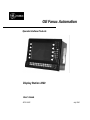
1
GE Fanuc Automation Operator Interface Products Display Station 2020 User's Guide GFK-1543C July 2000 GFL-002 Warnings, Cautions, and Notes as Used in this Publication Warning Warning notices are used in this publication to emphasize that hazardous voltages, currents, temperatures, or other conditions that could cause personal injury exist in this equipment or may be associated with its use. In situations where inattention could cause either personal injury or damage to equipment, a Warning notice is used. Caution Caution notices are used where equipment might be damaged if care is not taken. Note Notes merely call attention to information that is especially significant to understanding and operating the equipment. This document is based on information available at the time of its publication. While efforts have been made to be accurate, the information contained herein does not purport to cover all details or variations in hardware or software, nor to provide for every possible contingency in connection with installation, operation, or maintenance. Features may be described herein which are not present in all hardware and software systems. GE Fanuc Automation assumes no obligation of notice to holders of this document with respect to changes subsequently made. GE Fanuc Automation makes no representation or warranty, expressed, implied, or statutory with respect to, and assumes no responsibility for the accuracy, completeness, sufficiency, or usefulness of the information contained herein. No warranties of merchantability or fitness for purpose shall apply. The following are trademarks of GE Fanuc Automation North America, Inc. Alarm Master CIMPLICITY CIMPLICITY PowerTRAC CIMPLICITY 90–ADS CIMSTAR Field Control GEnet Genius Genius PowerTRAC Helpmate Logicmaster Modelmaster Motion Mate PowerMotion ProLoop PROMACRO Series Five Series 90 Series One Series Six Series Three VersaMax VuMaster Workmaster ©Copyright 1998-2000 GE Fanuc Automation North America, Inc. All Rights Reserved. Preface Content of This Manual This manual describes the features and operation of the following CIMPLICITY Display Station products: Catalog Number Description IC752WFB204 IC752WFB254 IC752SPL006 IC752WFB202 IC752WFB252 IC752SPL007 CIMPLICITY HMI for CNC with Windows NT - includes High Speed Serial Bus (HSSB) card IC752WFB203 IC752WFB253 CIMPLICITY HMI with Windows 95 IC850PCT300 CNC Display Station with Windows NT CIMPLICITY HMI with Windows NT Revisions to this Manual This version of this manual (GFK-1543C) contains the following changes as compared to the previous version (GFK-1543B): • Instructions for using the Image Recovery Disk – page 2-9. Related Publications GFK-1543C GFK-1189 CIMPLICITY® HMI for Windows NT™ and Windows ® 95 Important Product Information GFK-1180 CIMPLICITY® HMI for Windows NT™/CIMPLICITY HMI for Windows ® 95 CIMPLICITY Server for Windows NT™ Base System User Manual GFK-1181 CIMPLICITY® HMI for Windows NT™/CIMPLICITY HMI for Windows ® 95 CIMPLICITY Server for Windows NT™ Device Communications Manual GFK-1396 CIMPLICITY® HMI for Windows NT and Windows 95 CimEdit Operation Manual GFK-1341 CIMPLICITY® HMI/HMI for CNC operation manual iii Contents Chapter 1 Display Station 2020 Features............................................................................ 1-1 Feature Summary......................................................................................................1-2 Display Station Features ......................................................................................1-2 Optional Features................................................................................................1-3 Access Panel.............................................................................................................1-3 System I/O ...............................................................................................................1-3 Standard I/O .......................................................................................................1-3 ISA and PCI Card Expansion...............................................................................1-4 Network Interface .....................................................................................................1-4 Application Software.................................................................................................1-4 Chapter 2 Powerup and Software Installation ................................................................... 2-1 Initial Startup............................................................................................................2-1 Powering Up the Display Station Unit ..................................................................2-1 Setting Up Windows 95 Systems (WFB203, WFB253 Models)..............................2-2 Setting Up Windows NT Systems ........................................................................2-3 Configuring the Display Station to Run on a Microsoft Network ............................2-4 Login Recommendation ......................................................................................2-5 Registering Your CIMPLICITY Software...................................................................2-5 Installing Application Software..................................................................................2-6 Directory Structure..............................................................................................2-6 Windows NT Systems ....................................................................................................2-6 Windows 95 Systems .....................................................................................................2-6 Reloading Windows NT on the Hard Disk From CD .............................................2-7 Display Station 2020 Windows NT Touch Screen Driver Installation .....................2-7 Image Recovery........................................................................................................2-9 Instructions for Image Recovery ..........................................................................2-9 Shutting Down the Computer.....................................................................................2-9 Chapter 3 Hardware Installation......................................................................................... 3-1 Mounting Guidelines.................................................................................................3-1 Mounting Procedure..................................................................................................3-2 Installing Expansion Cards ........................................................................................3-3 Blanking Plates...................................................................................................3-5 Configuring Expansion Cards (Legacy ISA Only) .................................................3-6 Changing the Air Filter Element.................................................................................3-7 GFK-1543C v Contents Chapter 4 Connectors ........................................................................................................... 4-1 Power Input..............................................................................................................4-2 Connector Layout .....................................................................................................4-3 System I/O ...............................................................................................................4-4 Printer Port LPT1 .....................................................................................................4-4 Serial Communication Cables ....................................................................................4-5 Chapter 5 System Operation................................................................................................ 5-1 System Peripherals ....................................................................................................5-2 Hard Disk Drive..................................................................................................5-2 Floppy Disk Drive...............................................................................................5-2 CD-ROM Drive..................................................................................................5-3 External Keyboard and Mouse ...................................................................................5-3 Graphic System ........................................................................................................5-4 Graphics Controller.............................................................................................5-4 Display Types.....................................................................................................5-4 Operator Interfaces....................................................................................................5-5 Keypad...............................................................................................................5-5 Control and Status Functions ...............................................................................5-8 Touch Screen......................................................................................................5-9 Touch Screen Driver for Windows .......................................................................5-9 Touch Screen Calibration Procedure.....................................................................5-9 Setting the Backlight Dimming Control.............................................................. 5-10 Dimming Control Settings ...........................................................................................5-10 Setting the Timeout Period for Timed Mode ..............................................................5-11 CIMPLICITY Software........................................................................................... 5-11 Communications ..................................................................................................... 5-12 Chapter 6 BIOS Settings....................................................................................................... 6-1 Restoring Factory CMOS Settings..............................................................................6-1 CMOS Checksum Error.............................................................................................6-2 Chapter 7 Diagnostics and Troubleshooting....................................................................... 7-1 Self-Test Diagnostics ................................................................................................7-1 System Test and Initialization ..............................................................................7-1 System Configuration Verification .......................................................................7-1 Troubleshooting........................................................................................................7-2 Powerup.............................................................................................................7-2 Display...............................................................................................................7-3 Memory .............................................................................................................7-3 External PS2 Mouse............................................................................................7-4 Keyboard............................................................................................................7-4 vi Display Station 2020 User's Guide–July 2000 GFK-1543C Contents Communications .................................................................................................7-5 PLC/CPU Connection ....................................................................................................7-5 MODBUS RTU Communications.................................................................................7-5 Network Communications .............................................................................................7-6 Printing ............................................................................................................................7-6 Frequently Asked Questions ......................................................................................7-7 Hardware FAQs..................................................................................................7-7 Software FAQs...................................................................................................7-7 Appendix A Technical Data.................................................................................................... A-1 Mechanical Specifications ........................................................................................ A-1 Functional Specifications.......................................................................................... A-2 Filter Pads ............................................................................................................... A-4 GFK-1543C Contents vii Chapter Display Station 2020 Features 1 The Display Station 2020 is a high performance workstation designed primarily for use as a hardware platform for Human Machine Interface (HMI) and Supervisory Control and Data Acquisition (SCADA) software packages running under either Windows® 95 or Windows NT® operating systems. Each model in the Display Station 2020 family is a fully self contained PC compatible computer with a built-in flat screen display and resistive touch screen, housed in an industrial IP65 rated front panel mounted unit, weighing less than 16 kg (35.28 lbs.). The unit is housed in a rugged metal case to protect the system against dust, water, and damage. The enclosure provides front panel access to peripherals such as CD-ROM, floppy drive, PS/2 connector, and parallel ports. Display Stations are available with autoranging main power input unit for 115/230 VAC operation. The unit is supplied completely assembled and requires only mounting and connecting. The use of special clips to secure the unit to the panel eliminates the need for mounting holes and requires only one cut-out to mount the unit. Before powering up your system for the first time, you should refer to the procedures in Chapte 2, which contains information you need to set up the operating system and network communications. GFK-1543C 1-1 1 Feature Summary When you purchase a Display Station system, you receive: • Display Station industrial computer with CIMPLICITY HMI software and operating system software installed. (See “Standard Features” below. Demo only for IC850PCT300.) • Power cord • Installation hardware • CIMPLICITY software licenses and license agreements (not included in IC850PCT300) • Ethernet driver floppy disk and manual • Microsoft Windows documentation, software distribution, Certificate of Authenticity and license agreement Display Station Features Catalog Number IC752WFB202/252 IC752SPL007 IC752WFB204/254 IC752SPL006 DS2020, Windows NT DS2020, Windows NT with High Speed Serial Bus Card (HSSB) IC850PCT300 DS2020, Windows NT with CIMPLICITY HMI for CNC (Demo software only) IC752WFB203/253 DS2020, Windows 95 operating system CIMPLICITY HMI software Unlimited Point Count Development and Runtime software CPU Pentium, 233 MHz minimum* Hard disk 6.4 GB minimum* Floppy disk drive CD ROM drive 3.5 inch, 1.44 Mbyte 32x speed minimum* RAM 64 MB minimum* Display Stations allow you to install a maximum of 256MB of DRAM. Display Parallel ports Color TFT –SVGA 800 x 600 One LPT1 Serial port One RS-232 *Contact your local distributor for upgrades and options. 1-2 Display Station 2020 User's Guide– July 2000 GFK-1543C 1 Optional Features The following features are optional on many models in the Display Station range. Contact your GE Fanuc distributor for details. • Additional DRAM (SIMMs) • Higher Speed CPU • CIMPLICITY HMI software license (IC850PCT300 only) Access Panel A lockable front access panel provides access to the peripheral facilities, floppy disk, CD-ROM drive, printer port, keyboard and PS2 mouse connectors. This panel also incorporates a membrane keypad that provides full keyboard facilities. System I/O Standard I/O The Display Station 2020 provides the following I/O interface channels: • A single serial interface port is provided by the processor motherboard. It uses a standard 9-pin D type connector. • A single enhanced parallel port is also provided by the motherboard. This port is accessible at the front of the unit under the access panel. If the end application requires serial or parallel interfaces in addition to those provided by the standard system, these can be provided by the addition of specific ISA or PCI I/O cards. A wide selection of ISA and PCI cards is available from 3rd party sources to provide user flexibility. GFK-1543C Chapter 1 Display Station 2020 Features 1-3 1 ISA and PCI Card Expansion Display Station 2020 provides two expansion slots. The slots available are two ISA and one PCI. • One ISA slot • One PCI/ISA shared slot (not available with IC752WFB2x4 or IC752SPL006) All the expansion slots within the system allow the card to be clamped into place using a clamping bracket with screws adjustable to the height of the card. Network Interface The Display Station includes an autosensing 10/100 Ethernet adapter that provides a RJ-45 connector for unshielded twisted pair cable Application Software Display Stations 2020 are supplied with CIMPLICITY HMI software, which is preloaded before shipment of the Display Station. (Demo software only for IC850PCT300.) 1-4 Display Station 2020 User's Guide– July 2000 GFK-1543C Chapter Powerup and Software Installation 2 This chapter contains information you need to set up your Display Station’s operating system and network communications. For details on Windows 95 systems, refer to page 2-2. For details on Windows NT systems, refer to page 2-3. Initial Startup When you first power up your system, you will need to attach a standard PS2-type keyboard to the external keyboard port on the Display Station. When the system starts up, you will be required to enter the Product ID from the Windows 95 or Windows NT Certificate of Authenticity and other data to set up your system. Also, most configuration activities that you perform on a Display Station system can be more easily completed using a keyboard or may require a keyboard. For details on power supply input, see Chapter 4. Powering Up the Display Station Unit Caution Do not connect or disconnect external devices, such as a printer or a PS2 mouse or keyboard, while the unit is powered. Failure to observe this precaution could result in damage to the equipment. The power switch is located on the side of the Display Station unit next to the input power connector. To power up the unit, set the rocker switch to the on position. During power up, the processor will run its normal diagnostic checks and indicate the presence of any errors either with a screen prompt or with warning beeps. GFK-1543B 2-1 2 Setting Up Windows 95 Systems (WFB203, WFB253 Models) Before you get started, you need a PS2 keyboard. A PS2 mouse is also recommended to help navigate through the setup screens. 1. Plug in the keyboard, PS2 mouse (if available), and power cord. 2. Power on the unit. The Windows 95 Setup screen will appear. 3. Type your name. 4. Press the TAB key and type your company name 5. Press ENTER. 6. Read the license agreement 7. Click your choice. 8. Click Next. 9. Enter the Windows 95 Certificate of Authenticity number found on the front of your Windows 95 manual. Press ENTER. 10. The network card used in these systems supports Plug & Play installation. 11. Windows 95 will go through setup. 12. When prompted for Date/Time Properties, use your left and right arrow keys to set the time zone to your time zone. Press ENTER. 13. If you have a printer connected, click Next and select your printer model type. If not, click the Cancel button. The Welcome to Windows 95 window will appear. 14. Click Close for the Welcome to Windows 95 window. 2-2 Display Station 2020 User's Guide– July 2000 GFK-1543C 2 Setting Up Windows NT Systems Before you get started, you need a PS2 keyboard. A PS2 mouse is recommended to help navigate through the setup screens. 1. Plug in the keyboard, PS2 mouse (if available), and power cord. 2. Power on the unit. 3. Read license agreement 4. TA B to your choice and press ENTER. 5. Type your name 6. Press the TAB key and type your company name. 7. Press ENTER. 8. Enter your Windows NT Authentication number found on your Windows NT manual. You will need to use the TAB key to get to each number field. If correct, press ENTER. Note Computer names must be less than or equal to ten characters to run CIMPLICITY HMI software. Each computer on a network must have a unique name. 9. Enter a Computer name. This name should be unique to other computers on the same network. Press ENTER. Note Your system has been set up to enable autologon. Autologon allows the system to boot into Windows NT without your having to use a keyboard to press CTL-ALTDEL. 10. You will be prompted for a password. • To use the autologon feature, type admin for the password. Press the TAB key and type admin in the Confirm Password box. Press ENTER . • To skip the password, press ENTER • To assign a password, type in a password, press the TAB key, and type the password in the Confirm Password box. Press ENTER. 11. Press ENTER to continue with Windows NT Setup. 12. Click Finish. Note With Windows NT, it is highly recommended that you create an Emergency Repair Disk once you have completed the setup of your system. Go to Start/Run/Rdisk.exe. You will need to update this disk anytime you make a change to the hardware or software. GFK-1543C Chapter 2 Powerup and Software Installation 2-3 2 Configuring the Display Station to Run on a Microsoft Network Before setting up your new Display Station for the network, you should consult with your network administrator. Duplicate TCP/IP addresses and duplicate computer names on the same network can cause network problems. 1. Click the Start icon, then click Settings and Control Panel. 2. In the Control Panel window, double click the Network icon. The Network dialog box will appear. 3. In the Network dialog box, click the Identification tab. You will need to type in your Computer name, Workgroup name, and Computer Description. Note Computer names must be less than or equal to ten characters to run CIMPLICITY software. Each computer on a network must have a unique name. In Windows 95 systems, for Viewers and HMIs to be able to browse remote nodes, the local computer name must be entered into the /WINDOWS.000/HOSTS file. 4. To allow sharing, A. Go to the Configuration tab and click the File and Print Sharing button. The File and Print Sharing dialog box will appear. B. Check the File and Print Sharing options that you want and click OK. 5. To add the TCP/IP protocol, A. Go to the Configuration tab and click the Add button. The Select Network Component dialog box will appear. B. Click the Protocol icon and click Add. The Select Network Protocol dialog box will appear. C. In the Manufacturer list, select Microsoft. In the Protocol list, select TCP/IP. Click OK. D. Change the Address from 10.0.0.1 to a unique address. Change the default subnet mask 255.0.0.0 to your subnet mask. E. Click OK twice. 6. When you have finished setting up the Network, click OK in the Network dialog box. Click Yes to reboot your system now. 2-4 Display Station 2020 User's Guide– July 2000 GFK-1543C 2 Login Recommendation If you type admin as your Administrator password, your Display Station will automatically log on as Administrator. Log onto the system as Administrator when you power up the system. Doing so eliminates the requirement to log on to CIMPLICITY when you run the CIMPLICITY Demo or any other CIMPLICITY project that includes a user named Administrator. All CIMPLICITY projects are configured with an Administrator user by default. Registering Your CIMPLICITY Software (Not applicable to IC850PCT300 models) Licenses have been loaded for CIMPLICITY HMI Base, Trending, TCP/IP Communications, and Series 90 SNP Communications. If you purchase additional product options to run on the Display Station, it is necessary to contact GE Fanuc to update the system licensing. 1. Click Start, Programs, CIMPLICITY, HMI, Registration. 2. Click Next for new User. 3. Read the License Agreement and select Yes if you agree. 4. Fill in the User Information. 5. Click Next 6. Open your CIMPLICITY software box and find your license packs. Open each license pack and type the serial numbers in the fields provided. 7. Call the CIMPLICITY phone number that appears on the screen. Faxes and phone calls will be processed between 8 AM and 5 PM Eastern time, Monday through Friday, except for regularly scheduled holidays. Faxes and calls received after hours, on weekends, or holidays will be processed as soon as possible on the following business day. When you phone, please be prepared to provide GE Fanuc with the following information: • Your User information • CIMPLICITY serial numbers • The System Key Code generated during the registration procedure Note When it is installed without the authorization code, you can run the software as a fully functional system in two-hour increments. Your CIMPLICITY software can also be registered over the internet. Contact "Software Registration" at www.gefanuc.com/cimplicity. GFK-1543C Chapter 2 Powerup and Software Installation 2-5 2 Installing Application Software The Windows operating system and CIMPLICITY HMI software are loaded onto the Display Station unit at manufacture. If it is necessary to reload software, follow the instructions in the documentation supplied with the software. The following sections give tips for customizing the software for the Display Station platform. Directory Structure The contents of the Display Station hard drive, as shipped from GE Fanuc are listed below. Windows NT Systems C:\CIMCD\i386 CIMPLICITY CD C:\i386 Windows NT CD C:\TBASE Touch screen drivers C:\i386\DRVLIB.NIC\Intel 55 Network drivers C:\SP4\i386 Service pack 4 drivers C:\LS120 Imation Superdisk Floppy Backpack drivers Note If you reload any Windows NT component requiring files, such as network driver, you must reload service pack 4. To do this type: C:\SP4\UPDATE Windows 95 Systems 2-6 C:\CIMCD\i386 CIM CD C:\Windows\Options\CABS Windows 95 CD Display Station 2020 User's Guide– July 2000 GFK-1543C 2 Reloading Windows NT on the Hard Disk From CD To reload Windows NT you should follow the instructions in the Windows NT manual from Microsoft Corporation. After completing the installation, the BOOT.INI file must be modified to ensure that the touch screen works correctly. • Edit the BOOT.INI file and add the /noserialmice:com2 option to the end of each entry in the [operating systems] section of BOOT.INI. • If you have concerns about performing this step call the CIMPLICITY Hotline for assistance. Note You must use version TNdriver 1.26 or higher of the touch screen driver to avoid a system crash during boot up. You may need to set up the display driver in the event of a reload. Go to Control Panel/Display/Settings and set Colors to 65536, Resolution to 800 x 600, Refresh to 60 Hz, and Display Type to Chips & Technologies 65550. Display Station 2020 Windows NT Touch Screen Driver Installation If the Display Station touch screen drivers become corrupt, an experienced user can try re-installing the drivers and editing the boot.ini file by doing the following procedure: 1. Initial driver installation is completed by double clicking NT setup on the touch driver floppy disk. Once installed, the computer will request that you reboot the system. The touch screen will not work until you edit the NTboot.ini file in the root directory of Windows NT. A suggested procedure follows: 2. Open Windows Explorer. Clock View and the menu bar and make sure that you are viewing all files. 3. Click the (C:) drive to display all files. 4. Find the "boot" folder in your contents and right click. 5. Click the Properties option. 6. Click the General tab and make sure that all the attributes are unchecked: Archive, Apply, and Read-only. Once all boxes are unchecked, click Apply and then OK to return to Windows Explorer. 7. Double click the boot folder. Wordpad will display five lines of code. GFK-1543C Chapter 2 Powerup and Software Installation 2-7 2 8. Edit the fourth and fifth line of code to be identical to the code shown below: [boot loader] timeout=5 default=multi(0)disk(0)rdisk(0)partition(1)\WINNT="Windows NT Workstation Version 4.00" [operating systems] multi(0)disk(0)rdisk(0)partition(1)\WINNT="Windows NT Workstation Version 4.00" /NoSerialMice:Com2 multi(0)disk(0)rdisk(0)partition(1)\WINNT="Windows NT Workstation Version 4.00 [VGA mode]" /basevideo /sos /NoSerialMice:Com2 9. From the File menu, Save, then Exit Wordpad. 10. Click the Windows NT Start button and select Shut Down. 11. Turn the computer off. The NT driver will not load properly if you only restart the computer. It must be completely powered down. 12. Turn the computer on. 13. Click the Windows NT Start button, select Programs, Touch, and Touch Screen Control. 14. Click the Hardware Controls button and check that COM2 is selected. 15. Click the Calibrate button and follow the procedures for calibration. 16. Exit the program. 2-8 Display Station 2020 User's Guide– July 2000 GFK-1543C 2 Image Recovery The following procedure provides instruction on how to use the Field Image Recovery Disk (44A749863-G01Rxx). This disk will enable you to recover all software on your computer as received initially from GE Fanuc. Warning Before attempting an Image Recovery on your unit, make sure to record all critical settings and conduct a full back up of all CIMPLICITY Projects and critical documents. You will also need to have your CIMPLICITY registration and Microsoft Authorization Numbers handy. This process will clear all contents from your Hard Drive and return your system to the factory configuration. Instructions for Image Recovery 1. Prior to Image Recovery, a standard PS/2-type keyboard will need to be connected to the external keyboard port. 2. Insert the Field Image Recovery Disk into the Floppy Drive 3. After inserting the Recovery Disk, the system will prompt you to restore the image. Select <1> to “RESTORE SYSTEM TO ORIGINAL CONDITION”. If you have initiated this process in error, press <2> and Exit the Recovery program. 4. Select <1> again to “PROCEED WITH SOFTWARE RESTORE”. Choose <2> to cancel Recovery and exit to MS-DOS. 5. At this point the factory image will be recovered from a hidden partition on the Hard Drive. This will take approximately 12 minutes. When prompted, reboot your system. 6. After rebooting your unit, the system will bring you to the initial startup screens as received from the factory. Refer to the Display Station User’s Guide for Microsoft set-up, Network configuration, and CIMPLICITY HMI initialization. If you have any questions about this procedure, please contact 1-800 GE FANUC. MS-DOS is a registered trademark of Microsoft Corporation. Shutting Down the Computer Caution To avoid damaging files, always shut down Windows software before removing power from your Display Station product. To shut down Windows 95 or Windows NT software, select Shut Down from the Start menu. GFK-1543C Chapter 2 Powerup and Software Installation 2-9 Chapter Hardware Installation 3 This chapter describes the procedures for the safe location and securing of the Display Station 2020. The Display Stations have been designed to ensure simple installation of the system. A single cut-out in the mounting panel is all that is required when mounting the Display Station. No extra mounting holes are needed. Instead, ten spring loaded clips are supplied and are used to secure the unit from behind the mounting panel. This chapter also describes how to install ISA and PCI cards and how to change the air filter. Mounting Guidelines Note The IP65 rating applies to the front panel of the Display Station only and not to the rear of the unit. In order to meet the European EMC requirements for ESD (EN 61000-4-2) of +/4.0kV, the unit must be installed in a grounded metal enclosure when used in conjunction with the DeviceNet PCI/ISA expansion card (PC752DVM000). • In an industrial environment, the panel into which the unit is mounted should provide protection from dust, dirt and water. • The front access panel must be closed and locked for IP65 protection. • The panel should be capable of supporting the weight of the Display Station without distortion to the panel. The mounting clips will support a panel thickness of up to 10mm (0.39 inch). • All ten of the mounting clips must be fitted properly to achieve a good seal between the Display Station and the panel to which it is mounted. • Inlets and outlets must have at least 25mm of space around them and not be obstructed. Adequate airflow around the exterior of the unit is important to the interior temperature of the unit. Two fans are used to create air flow through the Display Station ensuring that a correct working temperature is maintained. The first of the fans is located within the unit and is used to cool the processor. The second fan is built into the power supply housing and blows air out of this unit. Incoming air passes through a filter that removes dust and dirt. The filter should be checked and replaced regularly. For details, see page 3-7. GFK-1543C 3-1 3 Mounting Procedure Use the following procedure to mount the Display Station 2020. 1. Cut an opening in the panel to the dimensions shown. The cut-out dimensions of 382 x 299mm (15.04" x 11.77") allow a 1.2mm clearance on each edge of the Display Station. The unit requires a minimum of 227mm (8.94") depth when mounted. 382mm (15.04") 299mm (11.77") 2. Position the Display Station in the cut-out and fit the ten spring loaded retaining clips into the slots on the Display Station. All ten clips must be used to produce a good seal. 3-2 Display Station 2020 User's Guide– July 2000 GFK-1543C 3 3. Screw in the tightening screws on each clip so that the spring is compressed by the nut. To ensure a good seal between the Display Station and the mounting panel, the clips must be tightened evenly. (Tighten each of the clips in turn, a little at a time.) 4. When the springs are fully compressed, no further tightening of the clips is necessary. The Display Station is locked into place. Installing Expansion Cards Display Station 2020 provides three expansion slots. • One ISA slot • One PCI/ISA shared slot (not available on IC752WFB2x4 and IC752SPL006 Models) If your card is a Legacy ISA type, follow the instructions on page 3-6, then proceed with installation. All the expansion slots within the system allow the card to be clamped into place using a clamping bracket with screws adjustable to the height of the card. The rear cover of the Display Station must be removed in order to access the ISA and PCI bus cards. Ten screws are used to secure the rear panel to the Display unit. When these screws are removed, the backplate will slide upwards and can then be lifted clear of the main unit. GFK-1543C Chapter 3 Hardware Installation 3-3 3 Warning To avoid a risk of electric shock, turn off power to the Display Station and disconnect the power supply before removing the rear cover from the unit. To disconnect the unit from the main power, remove the power cord. Caution To avoid damage from electrostatic discharge, adhere to the following precautions when installing ISA and PCI cards: 3-4 • The card is packaged in a static-safe bag which protects the product during shipping. Before removing the card from this bag, be prepared to handle it in a static-safe environment. • Wear a properly functioning antistatic strap and be sure that you are fully grounded. Never touch the card, or any components inside the Display Station, unless you are wearing an antistatic strap. • Any surface upon which you place the unprotected card should be static-safe, facilitated by antistatic mats, if possible. • Extra caution should be taken in cold, dry weather, when static charges can easily build up. Display Station 2020 User's Guide– July 2000 GFK-1543C 3 Blanking Plates Blanking plates are fitted to each unused card position, as shown in Figure 3-1. These blanking plates can be removed as necessary in order to install new cards. Any empty slots must have a blanking plate fitted, otherwise the air flow will not comply with agency requirements. Internal View of Display Station GFK-1543C Chapter 3 Hardware Installation 3-5 3 Configuring Expansion Cards (Legacy ISA Only) Caution For most applications an IRQ or address cannot be shared by more than one resource. If more than one resource is set to the same interrupt or address, the application may not respond properly and could cause your machine to lock up. Following these instructions when installing Legacy ISA cards will prevent problems with resource conflicts. Legacy ISA cards are the oldest standard and require memory, I/O, and IRQ settings to be manually set on the card using jumpers, DIP switches, or a configuration program. The card and system need to have the same hardware settings. 1. Connect a keyboard, turn on the system power, and press DEL when prompted to enter the BIOS Setup program. 2. Select PNP/PCI SETUP. 3. If the card requires one or more interrupts, go to an IRQ that currently reads "USED BY ISA: NO/ICU" and change it to "Yes" by pressing P AGE DOWN. Do not use an IRQ that already reads "Yes." Do not use an IRQ shown as "Used" in Windows NT diagnostic resources. 4. If the card requires memory space, enter the address and amount where "Memory Used" appears. Press ESC to exit this screen, and F10 to save and exit Setup. When the screen goes blank, turn off the power. 5. If the card has jumpers or DIP switches, set them so that they match the IRQ and memory addresses set in the BIOS Setup. 6. Set the I/O port settings of the card (if any) so that they fall within the ranges labeled "Available" in Table 2. 7. If the card is set up using a configuration program, proceed with installation, then run the card’s configuration program. Set the IRQ and memory address settings to be the same as those put into BIOS Setup. Set the I/O port settings (if any) to a range labeled "Available" in Table 3-1. Table 3-1. I/O Port Range Table 3-6 000-1FF Reserved 200-27F Available 280-2FF Reserved 300-377 Available 378-3DF Reserved 3E0-3EF Available 3F0-3FF Reserved Display Station 2020 User's Guide– July 2000 GFK-1543C 3 Changing the Air Filter Element The filter element should be changed or cleaned every three months, or sooner in dusty environments. If the air filter is not changed at suitable intervals, or if a non approved filter is used, the unit may overheat. For details of approved filter elements, refer to "Environmental Specifications" in Appendix A. The filter element is mounted to the inside of the back plate of the Display Station using one center securing nut. When it becomes necessary to change the filter, unscrew the center nut and remove the Filter Hold Down plate. Removing the rear cover of the unit is not necessary. To change the filter : 1. To prevent environmental contaminants from entering the unit, power down the unit prior to removing the filter. 2. Remove the Center Securing screw as shown in the photo below. There is no need to remove the rear cover of the CPU. 3. Carefully remove the Filter Hold down plate. 4. Remove the filter element and replace it with a new one. Refer to ordering information on page A-4 of the Appendix to obtain new filters. 5. Put the Filter Hold Down Plate in place and secure it to the backplate by tightening the center securing screw. Center Securing nut GFK-1543C Chapter 3 Hardware Installation 3-7 Chapter Connectors 4 This chapter describes the connector layout on the standard Display Station 2020. Keyboard and data connectors are provided on the proprietary cards fitted in the Display Station 2020. The documentation of the original manufacturers of these cards is supplied with the Display Station. • Keyboard (CPU card) • PS2 Mouse Port (CPU card) • Serial Ports COM 1 (CPU card) • Parallel Port – 25-pin (CPU card) • Network (PCI expansion card) For details about connectors on proprietary cards you have installed in the Display Station, refer to the manufacturer’s documentation provided with your card. GFK-1543C 4-1 4 Power Input Series 2020 Display Stations are powered by an internal, autoranging AC power supply unit that accepts 85 to 135 and 180 to 250 VAC input ranges. The power supply unit also provides a standard IEC outlet socket. The power supply input to the Display Station uses a standard IEC cable, which is provided with the unit. A rocker switch is provided to allow the system to be isolated from the input. The power supply unit and the power switch are recessed within the enclosure to ensure that they do not interfere with the mounting of the Display Station into the panel aperture. The power supply unit houses an integral ventilation fan that provides cooling for the power supply. For power supply details, refer to specifications in Appendix A. There are no user-serviceable fuses in these Display Station units. Warning For all equipment that is connected to a power outlet, the socket outlet shall be installed near the equipment and shall be easily accessible. 4-2 Display Station 2020 User's Guide– July 2000 GFK-1543C 4 Connector Layout Caution External devices (printer, external disk drive etc.) should not be powered up. Remote Video RJ-45 Com1 Side Panel Connectors Printer Port LPT1 Keyboard Mouse Front Panel Connectors GFK-1543C Chapter 4 Connectors 4-3 4 System I/O The Display Station 2020 provides the following I/O interface channels: • A single serial interface port is provided by the processor motherboard. It uses a standard 9-pin D type connector. • A single enhanced parallel port is also provided by the motherboard. This port is accessible at the front of the unit under the access panel. If the end application requires serial or parallel interfaces in addition to those provided by the standard system, these can be provided by the addition of specific ISA or PCI I/O cards. A wide selection of ISA or PCI cards is available from 3rd party sources to provide user flexibility. • Dual channel RS232 asynchronous adapter • Dual channel RS422/485 asynchronous adapter • Printer port output/input adapter. Printer Port LPT1 A 25 pin D type female connector mounted under the access panel of the Display Station is used for the printer port. Pin 4-4 Assignment Pin Assignment 1 Strobe 10 Acknowledge 2 Data Bit 0 11 Busy 3 Data Bit 1 12 Paper End 4 Data Bit 2 13 Select Out 5 Data Bit 3 14 Auto Feed XT 6 Data Bit 4 15 Error 7 Data Bit 5 16 Initialize Printer 8 Data Bit 6 17 Select In (from Printer) 9 Data Bit 7 18 to 25 Ground Display Station 2020 User's Guide– July 2000 GFK-1543C 4 Serial Communication Cables RS-232C Name PIN Assignment CF 1 DCD (Data Carrier Detect) BB 2 RX (Receive Data) BA 3 TX (Transmit Data) CD 4 DTR (Data Terminal Ready) AB 5 GND (Signal Ground) CC CA 6 7 DSR (Data Set Ready) RTS (Request to Send) CB 8 CTS (Clear to Send) CE 9 RI (Ring Indicator) To ensure that the installation meets the EMC radiation specification, the serial cables must comply with the following requirements: GFK-1543C • The cables must be shielded. • The D type connector covers must provide EMC shielding (e.g. Metallized plastic or die cast metal covers). • The cables must be terminated with 360 degree termination of the shield, as illustrated below. Chapter 4 Connectors 4-5 Chapter System Operation 5 This chapter provides details of system operation. The following topics are covered: GFK-1543C • System Peripherals • External Keyboard and Mouse • Graphic System • Operator Interfaces • CIMPLICITY Software • Communications 5-1 5 System Peripherals Hard Disk Drive The system provides an internal 3.5 inch bay which is dedicated to the system hard drive. The Display Station system has a single internal hard disk drive for the mass storage of data. The disk drive is a standard unit with EIDE/ATA-2 interface. Hard disk bay Floppy Disk Drive Display Station 2020 systems have a single internal 3.5 inch floppy disk drive which is located under the access panel. The floppy drive is a standard 3.5 inch, 1 inch high unit capable of operating in both low density (720KB unformatted) and high density (1.44 MB unformatted) modes. 5-2 Display Station 2020 User's Guide– July 2000 GFK-1543C 5 CD-ROM Drive Display Station 2020 systems include an integral CD-ROM drive which is located under the front access panel. CD-ROM Drive Floppy Disk Drive External Keyboard and Mouse An external keyboard and mouse (both using PS2 connectors) can be attached via the connectors under the front access panel. The touch screen and mouse will work simultaneously if the mouse is Microsoft or IBM PS2 compatible. If you are installing an optional serial card, none of the ports can be configured as COM 2, which conflicts with the touch screen. Keyboard GFK-1543C Chapter 5 System Operation Mouse connector 5-3 5 Graphic System Graphics Controller A dedicated graphics controller card is used in the PC enclosure inserted into a PCI expansion slot on the motherboard to provide the interface for the panel display. The following features are supported: • Display panel resolutions from VGA (640 x 480) up to XGA (800 x 600), color support being from 512 to true color. It is recommended that the Display Station be run in the resolution configured at the factory. • An external CRT interface using 15 pin high density D type connector. Note that the remote video output shown below is for diagnostic use only. A BIOS mode is necessary before the external port can be made functional. Remote Video Display Types The standard Display Station 2020 system includes a 12.1 inch color TFT (SVGA resolution) screen. The flat screen display has the following features: 5-4 • High Luminance (equal to or greater than 200cd/m2) • Wide angle viewing • A built-in backlight with a long life backlight tube (equal to or greater than 25,000 hrs), • Control of the backlight to maximize the tube lifetime. (See page 5-9). Display Station 2020 User's Guide– July 2000 GFK-1543C 5 Operator Interfaces Keypad The Display Station 2020 incorporates an integral keypad. • The main keypad returns the same scan codes as a standard PC/AT keyboard, listed in Table 5-1. • The lift-up panel provides 24 user-configurable function keys. The lift-up panel has two key locks which can be used to lock it in the closed position. • If an external PC/AT keyboard is connected, the integral keypads remain functional. It is not necessary to reboot the Display Station when you plug in an external keyboard. • The membrane keys located along the sides of the display are the same as function keys F1 through F10 plus the left Control key. Main Keypad Membrane Keys Shift+ F1 through Shift + F5 Shift + F6 through Shift + F10 Lift-up Panel GFK-1543C Chapter 5 System Operation 5-5 5 Table 5-1. Membrane Keypad Scan Codes Without FN Key Display Station Key 5-6 AT Command Make Scan Code (Hex) With FN Key AT Command with FN Key Held Make Scan Code with FN Held 7 7 0837 \ 2B5C 8 8 0938 / 352F 9 9 0A39 : 273A 4 4 0534 . 342E 5 5 0635 , 332C 6 6 0736 " 2822 1 1 0231 % 0625 2 2 0332 [ 1A5B 3 3 0433 ] 1B5D 0 0 - 0B30 0C2D _ - + 0C5F 0D2B FN None (Note 1) None None None ENTER Enter 1C0D None None DELETE Delete 53E0 None None PRINT Ctrl + P 1910 None None HOME Home 47E0 None None SPACE Space 3920 None None BACKSPACE Backspace 0E08 None None ESCAPE Escape 011B None None INSERT Insert 52E0 * 092A PAGE↑ Pageup 49E0 None None PAGE↓ Pagedown 51E0 None None Alt Alt None None Tab Tab 0F09 Shift Tab 0F00 END End 4FE0 None None ← Left arrow 4BE0 None None → Right arrow 4DE0 None None ↑ Up arrow 48E0 None None ↓ Down arrow 50E0 None None F1 F1 3B00 A 1E41 F2 F2 3C00 B 3042 F3 F3 3D00 C 2E43 F4 F4 3E00 D 2044 F5 F5 3F00 E 1245 F6 F6 4000 F 2146 F7 F7 4100 G 2247 F8 F8 4200 H 2348 F9 F9 4300 I 1749 F10 F10 4400 J 244A F11 F11 8500 K 254B F12 F12 8600 L 264C Display Station 2020 User's Guide– July 2000 GFK-1543C 5 Table 5-1. Membrane Keypad Scan Codes - Continued Without FN Key Display Station Key Make Scan Code (Hex) AT Command with FN Key Held Make Scan Code with FN Held S1 Start Button (WinMenu) Note 2 E02F M 324D F13 CTRL F1 5E00 N 314E F14 CTRL F2 5F00 O 184F F15 CTRL F3 6000 P 1950 F16 CTRL F4 6100 Q 1051 F17 CTRL F5 6200 R 1352 F18 CTRL F6 6300 S 1F53 F19 CTRL F7 6400 T 1454 F20 CTRL F8 6500 U 1655 F21 CTRL F9 6600 V 2F56 F22 CTRL F10 6700 W 1157 F23 CTRL F11 8900 X 2D58 F24 CTRL F12 Context Menu (Note 3) 8A00 Y 1599 Z 2C5A Unnamed Upper Left Shift F1 5400 None None 2nd from top left Shift F2 5500 None None left center Shift F3 5600 None None 2nd from bottom left Shift F4 5700 None None Unnamed Lower Left Shift F5 5800 None None Unnamed Upper Right Shift F6 5900 None None 2nd from top right Shift F7 5A00 None None right center Shift F8 5B00 None None 2nd from bottom right Unnamed Lower Right Shift F9 5C00 None None Shift F10 5D00 None None S2 GFK-1543C AT Command With FN Key Chapter 5 System Operation 5-7 5 Table 5-1. Notes: 1. The FN key produces no scan codes on its own, but modifies the scan codes produced by the other keys as indicated in the table above. 2. The S1 key produces the same scan code as that for a Microsoft Win95\98 compatible keyboard. It performs the same function selecting the Windows Start icon. 3. The S2 key produces the same scan code as that for a Microsoft Win95\98 compatible keyboard. It performs the same function as clicking the left mouse button, to produce a popup menu. Control and Status Functions The Display Station 2020 includes a control/status panel, located by the right hand key lock. The LEDs and keys on this small membrane panel have the following functions: 1 2 3 6 5 4 Controls and Indicators 5-8 Callout Type Function 1 2 3 4 5 6 Key Controls the Backlight Mode of operation. Key Controls the flat panel display contrast (only applicable for the STN technology). LED Indicates the status of the flat panel display backlight control mode. LED Indicates IDE drive activity when an IDE device is being read from or written to. LED Indicates system power (lighted when power is applied). LED Provides a general status indicator that can be used by any additional hardware installed on the system. Display Station 2020 User's Guide– July 2000 GFK-1543C 5 Touch Screen The Display Station 2000 range includes a resistive overlay touch screen on the flat panel display. It has a touch resolution of 1024 x 1024 touch points (independent of screen size) and provides an efficient and reliable method of entering information, suitable for HMI and SCADA software packages. The screen responds to the touch of your finger with or without a glove. The touch screen is connected internally to the COM 2 serial port, which allows it to function with SCADA software. If you install a card that has settings that conflict with those of the COM 2 serial port, you will need to change the card’s configuration. Touch Screen Driver for Windows SCADA software which runs under Microsoft Windows is supplied with a driver (Twdriver) to interface with the touch screen surround. The integral touch surround of the Display Station is internally connected to COM2. Parameters must be set within the driver so that they match the hardware settings. The factory default settings are: COM Port = COM 2 I/Q Address = 2F8 Hex IRQ = 3 These parameters are written into the system registry file by the driver setup utility. The driver is installed, configured and calibrated at the time of manufacture. Touch Screen Calibration Procedure Due to fluctuations in system requirements and individual touch resistance, it may be necessary to calibrate your touch screen after you have licensed your Display Station but before normal use. To calibrate your touch screen: 1. Ensure that an external keyboard is attached to your system. 2. Press the Ctrl and Esc keys simultaneously. 3. Press the up arrow key until Programs is highlighted. 4. Press the right arrow key once, and then the down arrow key until the touch option is highlighted. 5. Press the right arrow key once and the down arrow key until Touchscreen is highlighted and press the Enter key. This opens the Touch Screen Control Program window. 6. Press the Alt and C key simultaneously to activate the calibration program. 7. Follow the instructions on the screen to calibrate your touch screen. 8. Exit the program after successful calibration of the touch screen. GFK-1543C Chapter 5 System Operation 5-9 5 Setting the Backlight Dimming Control Display Stations incorporate a backlight dimming control to extend the life of the backlight tubes. The dimming control is operated by using the backlight control button located on the control/status panel as with the contrast control. Dimming Control Settings Default Setting At power up, the backlight control is set to the default setting. This gives a time out period of 5 minutes that the backlight stays fully on, after which the backlight will dim. Mode Setting The backlight can be operated in three modes: Timed Mode - LED on Full Constant Mode - LED off Dim Constant Mode - LED off To step the system through the three modes, apply single presses of the Backlight Control Button. Timed Mode This is the default mode. In the Timed Mode, you can set the period of time for which the backlight operates at full power. When the time set expires, the backlight display is reduced to Dim and remains at the dim setting until the next interface input using the touch screen or keypad. If the system is powered down, when the unit is powered up again the default settings will be in effect. You must remake any settings for the control of the backlight. Full Constant Mode If the Backlight Control Button is pressed once when the system is operating in Timed Mode, the Display Station will operate in Full Constant Mode. In this mode, the backlight is constantly on. Dim Constant Mode Pressing the Backlight Control Button a second time selects the Dim Constant Mode. In this mode the backlight displays constantly on the Dim setting. 5-10 Display Station 2020 User's Guide– July 2000 GFK-1543C 5 Setting the Timeout Period for Timed Mode You can configure the timeout period so that the backlight stays fully on for a period of between 1 to 30 minutes before dimming. To set the timeout period: Press and hold the Backlight Control Button for more than 2 seconds. The backlight control LED will begin to flash. Each flash of this LED indicates that 1 minute has been added to the time out period. If the LED is allowed to flash three times, for example, and the button is then released, the backlight will dim after a period of three minutes has elapsed. CIMPLICITY Software For detailed software operating instructions, refer to the following documentation. GFK-1189 CIMPLICITY® HMI for Windows NT™ and Windows ® 95/98 Important Product Information GFK-1180 CIMPLICITY® HMI for Windows NT™/CIMPLICITY HMI for Windows ® 95/98CIMPLICITY Server for Windows NT™ Base System User Manual GFK-1181 CIMPLICITY® HMI for Windows NT™/CIMPLICITY HMI for Windows ® 95/98CIMPLICITY Server for Windows NT™ Device Communications Manual GFK-1341 CIMPLICITY® HMI/HMI for CNC operation manual GFK-1396 CIMPLICITY® HMI for Windows NT and Windows 95/98 CimEdit Operation Manual More information can be found at www.cimplicity.com. GFK-1543C Chapter 5 System Operation 5-11 5 Communications For information on the hardware setup for device communications, refer to CIMPLICITY® HMI for Windows NT™/CIMPLICITY HMI for Windows ® 95/98CIMPLICITY Server for Windows NT™ Device Communications Manual, GFK-1181 Your Display Station has been configured with networking components that enable you to establish new networks or connect to existing networks easily. If you intend to use Microsoft NetBEUI, TCP/IP, or Direct Cable Connection, some minimal setup changes are required before you can use the system for network applications. In both Windows 95/98 and Windows NT systems, these settings are changed using the Network application in the Control Panel program group. Installed Network Components Network Component Comments PCI Network Adapter Automatically configured in system TCP/IP Default settings must be changed before connecting to an existing network. Contact your network administrator for appropriate settings. NetBEUI Default settings must be changed before connecting to an existing network. Contact your network administrator for appropriate settings. System Identification Computer Name: Each system is uniquely identified by its serial number and can be renamed before adding it to an existing network Workgroup: The default workgroup is Workgroup. This should be renamed before adding it to an existing network. Caution The IP Address must be changed to a unique address. If it is not changed, conflicts could occur on your network. Note On any Display Station product with the HSSB card, only use the TCP/IP protocol. Do not install any other protocols. Note For Windows NT systems: If any component is removed and re-installed, the Service Pack will need to be run after installation. Path is: C:\SP4\i386\5P4i386 5-12 Display Station 2020 User's Guide– July 2000 GFK-1543C Chapter BIOS Settings 6 It is normally not necessary to change the hardware configuration settings in the CMOS memory. If settings become corrupt, follow the procedures here to reload the factory configuration. Restoring Factory CMOS Settings Connect a keyboard and turn on the power. Enter the Setup mode by pressing the DEL key when prompted during the computer power-up sequence. A screen will appear offering several options for changing settings, restoring default settings, and other functions. Follow these instructions to restore the factory configuration. 1. Select the Load Setup Defaults option. Then, select the Save CMOS settings option. You will be prompted to exit. Do not exit at this time. 2. Go into Standard CMOS Setup and make the following selections: Type Mode Primary HDD master AUTO AUTO Primary HDD slave AUTO AUTO Secondary HDD master AUTO AUTO Secondary HDD slave AUTO AUTO Drive A 1.44 MB 3.5” drive Drive B NONE All Faults Note: if the Display Station does not have an integral membrane keyboard, this should be set to “Ignore Keyboard error.” Halt on Errors Exit Standard CMOS Setup. 3. Go into Integrated Peripherals Setup. Set parallel port to ECP+EPP. 4. Select Save and Exit Setup. The startup sequence should begin now. The system is now configured with factory CMOS settings. GFK-1543C 6-1 6 CMOS Checksum Error If the CMOS battery has failed, the following error messages will be displayed on the screen: CMOS checksum error - Defaults loaded CMOS battery failed If you see the above message, you can still operate the Display Station by pressing the DELETE key and manually setting up the system. (You will need to set up the computer each time the system is powered up.) For setup parameters, refer to “BIOS Settings.” This battery has a lifetime of up to 10 years under normal operating conditions. If the battery failed, contact the GE Fanuc Hotline. 6-2 Display Station 2020 User's Guide– July 2000 GFK-1543C Chapter Diagnostics and Troubleshooting 7 This chapter consists of “Self-Test Diagnostics,” “Troubleshooting,” and “Frequently Asked Questions.” “Self-Test Diagnostics,” describes how to respond to errors that could be detected by the automatic self test that is performed each time the Display Station powers up. “Troubleshooting” contains tables of symptoms, their possible causes, and recommended corrective actions. “Frequently Asked Questions” contains answers to frequently asked questions. Self-Test Diagnostics The computer automatically performs self-test diagnostics each time it is powered up. The self-test consists of a series of checks that verify correct performance of the computer hardware. When the self-test is being performed, you will see the message XXXX KB OK displayed on the screen, where XXXX is a number that increases until it matches the amount of usable memory. System Test and Initialization These routines test and initialize board hardware. If the routines encounter an error during the tests, you will see an error message on the screen. There are two kinds of errors: fatal and non-fatal. If a non-fatal error occurs, the system can usually continue the boot up sequence. Non-fatal error messages usually appear on the screen with the following instruction: press <F1> to RESUME Write down the message and press the F1 key to continue the bootup sequence. System Configuration Verification These routines check the current system configuration against the values stored in the CMOS memory. If they don’t match, the program will generate an error message. To correct this condition, you will need to run the BIOS setup program and correct the configuration information in memory. There are three situations in which you might need to change the CMOS settings: 1. You are starting your system for the first time. 2. You have changed the hardware attached to your system. 3. The CMOS memory had lost power and the configuration information has been erased. If this has happened, call GE Fanuc’s Hotline Support at 1-800-GE-Fanuc. (800-433-2682). GFK-1543C 7-1 7 Troubleshooting Powerup Symptom Possible Causes Power not on (PWR indicator is not lit or display completely dark). Make sure that Display Station is plugged in. Make sure that power source is functioning properly. Display is blank (PWR indicator is lighted). Non-System disk or disk error message displayed. See “Display” on page 7- 3. See “Display” on page 7- 3. Disk in floppy disk drive. Remove floppy disk and then reboot or cycle power . Safe Recovery Error message displayed. Occurs on initial power up if the unit is accidentally turned off without first shutting down the Windows 95 software. The Display Station will power up normally. Memory count during powerup self-test is incorrect. Optional SIMM is installed incorrectly or is incompatible with the Display Station CPU. Make sure that the appropriate memory is installed correctly. CMOS checksum error — Defaults loaded CMOS battery failed CMOS battery failure. Note: This battery has a lifetime of up to 10 years under normal operating conditions. For more information, see “CMOS Checksum Error” in Chapter 6. A screen appears just after powerup, or just after reset, which has the title “CMOS Setup Utility.” The D EL key has been accidentally pressed. Cycle power again. The Display Station will power up normally. The Display Station reset even though the power was not interrupted. The CTRL-ALT-D EL keys were pressed twice at the same time. This should never be done, unless you are attempting to reset the Display Station. A:> appears instead of software. Hard disk error, insert system disk message displayed upon startup. A system floppy disk is inserted. Remove disk and cycle power. Factory CMOS settings have been corrupted. This is a temporary situation that occasionally occurs due to CMOS battery drain. See chapter 6, "BIOS Settings," to verity that Auto Detect is set in CMOS Settings. Also refer to page 41 in the ASUS Motherboard manual. message displayed. 7-2 Solution Display Station does not power up. Display Station 2020 User's Guide– July 2000 GFK-1543C 7 Display Symptom Possible Causes Solution Characters are dim. Computer screen is in direct light. Change lighting or adjust contrast. Display is blank (PWR indicator is lit). Screen temperature is outside operating range. If Display Station is in direct sunlight, move it and allow it to cool. Display Station is set up for invalid video mode. Reboot. Windows NT models: select VGA Mode Windows 95 models: press F8 when “Starting Windows 95” appears, then select Safe Mode. If Windows is now displayed, go into Control Panel, Display Settings, and change settings to the correct video driver and mode. Contact GE Fanuc’s CIMPLICITY hotline for more information. Cursor on touch screen does not correspond exactly to touch. Screen saver is active. Touch a key on the keypad. Touch screen needs calibration. Refer to "Touch Screen Calibration Procedure" in Chapter 5. Memory Symptom GFK-1543C Possible Causes Solution Memory count during powerup self-test is incorrect. Optional SIMM is installed incorrectly or is incompatible with the Display Station CPU. Make sure that the appropriate memory is installed correctly. Out of Memory message is displayed or insufficient memory error occurs during operation. System ran out of memory for the application. Check the memory requirements for the application. (Refer to the application documentation.) Install additional memory. Too many terminate and stay resident (TSR) programs running. Modify the startup folder to use only those TSR applications that are really needed. Chapter 7 Diagnostics and Troubleshooting 7-3 7 External PS2 Mouse Symptom Cursor does not respond to mouse movement Possible Causes Solution Mouse not plugged in. Power down Display Station. Plug mouse into mouse port on Display Station and reboot. The type of mouse is not supported. Use a PS2 mouse. System is busy. Press CTRL-ALT-DELETE to view task list. Mouse not detected. Restart Display Station product with external mouse connected. Keyboard Symptom External keyboard locks up 7-4 Possible Causes Solution The type of keyboard is not supported. Use a Key Tronic keyboard. (Most keyboards will work. However, we recommend a keyboard manufactured by Key Tronic.) Keyboard not plugged into keyboard port on Display Station. Plug keyboard in. System is busy. Press CTRL-ALT-D ELETE to view task list. Display Station 2020 User's Guide– July 2000 GFK-1543C 7 Communications PLC/CPU Connection Symptom CIMPLICITY does not communicate with a PLC that has been autoconfigured (AUTOCONFIG/DEFAULT/I/O error). Communications between the host computer and the controller are unsuccessful. Possible Causes The system is attempting to communicate with a 90-30 PLC using the SNP driver and a CIMPLICITY project. COM port not configured in system. Solution 1. With the PLC powered up and connected to the Display Station, establish communication between the Display Station and PLC via the 90-30 SNP driver. 2. Using a Hand-Held Programmer, toggle the Default I/O (Enable or Disable) configuration parameter for the CPU. Communications between the Display Station and the PLC will be stopped. (Communications are stopped when you toggle from Enable to Disable, or vice versa.) 3. Power cycle the PLC. Verify that the COM port is configured in the system. Cabling between computer and controller. Verify that the cable between the computer and the controller is correctly wired. Baud rate and parity configured incorrectly. Verify that the baud rate and parity on the computer are consistent with those on the controller. Wrong address. Verify that the slave address is correct. MODBUS RTU Communications Symptom Communications between the host computer and the controller are unsuccessful. GFK-1543C Possible Causes Solution COM port not configured in system. Verify that the COM port is configured in the system. Cabling between computer and controller. Verify that the cable between the computer and the controller is correctly wired. Baud rate and parity configured incorrectly. Verify that baud rate and parity on the computer are consistent with those on the controller. MODBUS port not configured for RTU communications. Verify that the controller's MODBUS port is configured for RTU communications. Wrong address. Verify that the slave address is correct. Chapter 7 Diagnostics and Troubleshooting 7-5 7 Network Communications Symptom Conflicts on network. Possible Causes IP Address not unique. Solution Change the IP address to a unique address. (Contact your system administrator if this or other settings need to be changed.) Printing Symptom 7-6 Possible Causes Solution Printer will not turn on. Cables not connected properly. Printer power cord not plugged in. Ensure that the cables are properly connected and that the power cord is connected to the electrical outlet. Printer will not print. Printer is not turned on. Turn on the printer Printer is not online. The device drivers for your application are not installed. Set the printer to online. Install the correct printer drivers for your application in Windows. Printer that is set up for a network is not connected to the network. Connect the printer to the network. Printer cable is too long, unshielded, or defective. Replace the cable. Printer is offline. Paper tray is empty. Fill the paper tray with paper. Set printer to online. Printer prints garbled information. Correct printer drivers not installed. Install the correct printer driver. Cable is not connected properly. Ensure that the printer cable is connected properly to the computer. Problem specific to printer. Run a printer self-test. Refer to the documentation provided with your printer for instructions. If the selftest fails, the problem is printerspecific. The printing section of the software documentation and in Windows online Help may also be helpful. Display Station 2020 User's Guide– July 2000 GFK-1543C 7 Frequently Asked Questions Hardware FAQs How do I upgrade the Display Station RAM or CPU in my Display Station? All Display Station products contain at least 64MB RAM and 233 MHz Pentium processor. Upgrades are available at time of initial order through the Display Station “upgrade” package (IC752WFB25x). All RAM or CPU upgrades outside the factory may invalidate the warranty. Contact the Support Hotline at 1-800-GE-FANUC for more information. How can I get a larger hard drive installed in my Display Station? Upgraded hard drives are available only at initial order point. If available, a larger hard drive is included as part of the Display Station upgrade package (IC752WFB25x,). All hard drive upgrades outside the factory will invalidate the warranty. Contact the Support Hotline at 1-800-GE-FANUC for more information. Software FAQs What HMI software comes preloaded on the Display Station product? Beginning in mid-February 1997, all IC752WFB/SPL units are preloaded with the full point count version of HMI software. You can get either Windows 95 or Windows NT operating system with the development/runtime packages. All Display Station products come with server packages but can be operated as viewers. IC850PCT300 models are available from the factory with a Demo version of CIMPLICITY HMI only. See http://www.gefanuc.com/hmi for ordering information. Will Display Station products with limited CIMPLICITY HMI point counts be offered? Some Display Stations are available with limited point count packages. Contact your distributor for more information. Can I log on to an NT System without typing a password? All systems have autologon enable for Administrator with admin (lower case) as the password. To disable the screen logon message, refer to the CIMPLICITY Web page at http://www.cimplicityhmi.com/appnote/logon.htm. The application note provided at this Web site describes how to create a default logon for the operating system that also acts as a logon for CIMPLICITY so that you only need to turn on the machine to have CIMPLICITY come up and be ready for use. How long is the period that the CIMPLICITY HMI software will run without authorization? CIMPLICITY HMI will run for four days after initial load. Due to normal delays in shipping and purchasing, this four-day period will usually have expired by the time the end-user receives their unit. In such case CIMPLICITY will default to a two-hour limit. You should go ahead and register your CIMPLICITY software immediately upon start-up. GFK-1543C Chapter 7 Diagnostics and Troubleshooting 7-7 Appendix Technical Data A Mechanical Specifications Front Assembly The Display Station 2020 provides a display screen and a built-in operator keypad and access panel. The whole of the front panel assembly is engineered to IP65 standards. Keypad Two keypads are used, a main keypad and the control panel. They are manufactured from a chemically resistant polyester. All the keys provide tactile feedback. Main Chassis The main chassis houses the motherboard which is mounted securely in a vertical plane. Plug-in boards are mounted in a horizontal plane perpendicular to the front of the Display Station. The housing for the card connectors is recessed so that the card interfaces do not protrude beyond the profile of the main housing. Rear Cover The rear cover of the unit is fixed to the main chassis so that emissions are minimized. The cover can be removed easily without breaking any electrical connections. Panel Mounting System Ten spring-loaded clamps are provided for mounting the Display Station to a panel. GFK-1543C A-1 A Functional Specifications CPU and Memory Microprocessor Pentium 233MHz minimum∗ User Memory Minimum 64Mbyte * Operating System Windows 95 or Windows NT Hard Disk 6.4Gbyte minimum* , IDE standard 3.5 inch mounting CD-ROM Standard Read only 32x CD-ROM drive Floppy Drive Supports 3.5-inch, 1.44Mb PC format floppy disks PC Backplane ISA bus card slots One card using full length slot (Available) PCI bus card slots Two cards using half length slots – one graphics card and one Ethernet card (Not Available) Accommodates one full length or one half length card (Not Available with IC752WFB2x4 or IC752SPL006) +5VDC 1.2 A approx +12VDC 0.1 A approx -12VDC 0.1 A approx Shared slot Total current available for sharing by up to 2 user cards Display Display Variants 12 inch Color TFT – SVGA Active Display Area 12 inch - 246 x 184.5 mm Power Requirements AC Models AC Input Power Rating AC Output ∗ A-2 85 to 265 VAC, 200W autoranging 85 to 265V, 47 to 63Hz; 2/4A 115V: 2A 230V: 1A Contact your local distributor for upgrades. Display Station 2020 User's Guide– July 2000 GFK-1543C A Ports Parallel Port Serial Ports One: LPT1 COM1 external RS232 port Keyboard Port PS2 Mouse Port PS2 Physical Dimensions Physical Characteristics Panel Cutout Weight (base unit with no optional cards installed) GFK-1543C Appendix A Technical Data 402mm wide (15.8 inches) 319mm high (12.6 inches) 200mm deep (7.9 inches) Width: 382mm (15.0 inches) Height: 299mm (11.8 inches) 15.6Kg (34.3lbs) A-3 A Filter Pads Dimensions Material Performance Requirements 80mm by 80mm P15/150B Retain 75% by weight of dust particles down to 5-10 microns in size Withstand temperatures to 100° C Provide flame resistance to BS5588 and DIN53438 Note: Filter pads (reference FP80T) are available from: PAPST-MOTOREN GmbH & Co KG Hermann-Papst-Straße 1 78112 St. Georgen/Schwarzwald Postfach 14 35 Tel: (0 77 24) 81-0 Fax: (0 77 24) 81-309 http://www.papst.de/home.html A-4 Display Station 2020 User's Guide– July 2000 GFK-1543C Index A Access panel, 1-3 Air filter element, 3-7 Air flow, 3-1 Application software, 1-4 Audible warning, 2-1 Autologon, 2-3 B BIOS settings, 6-1 Blanking plates, 3-5 C Cards Error messages AUTOCONFIG/DEFAULT I/O, 7-5 CMOS checksum error, 6-2, 7-2 CMOS Setup Utility, 7-2 Disk Error, 7-2 Insufficient memory, 7-3 non-fatal, 7-1 Non-system disk, 7-2 Out of Memory, 7-3 Safe Recovery, 7-2 External keyboard and mouse, 5-3 F Field image recovery disk, 2-9 Filter changing, 3-7 installation, 3-3 Catalog numbers Display Station IC752CTD450, 1-2 CD-ROM drive, 5-3 CIMPLICITY software operation, 5-11 CMOS battery, 7-2 CMOS Battery, 6-2 CMOS checksum error, 6-2 CMOS settings restoring, 6-1 self-test diagnostics, 7-1 COM1, COM2 location, 4-3 pinout, 4-5 Communications, 5-12 troubleshooting, 7-5 Configuring the Network Windows 95/98, 2-4 Connectors, 4-1 Control and status functions, 5-8 Controls and indicators, 5-8 D Diagnostics bootup sequence, 7-1 self-test, 7-1 system configuration verification, 7-1 system test and initialization, 7-1 Dimming control settings, 5-10 Display troubleshooting, 7-3 GFK-1543C E Filter pads, A-4 Floppy disk drive , 5-2 Frequently asked questions, 7-7 G Graphic system, 5-4 H Hard disk drive, 5-2 I I/O, 1-3 Image recovery, 2-9 Indicators, 5-8 Initial startup, 2-1 Installation cards, 3-3 panel mounting, 3-1 Installed network components, 5-12 Installing application software, 2-6 K Keyboard troubleshooting, 7-4 Keypad, 5-5 L LEDs, 5-8 Legacy ISA cards, 3-6 Login recommendation, 2-5 LPT1 Index-1 Index location, 4-3 pinout, 4-4 M Memory troubleshooting, 7-3 MODBUS RTU communications troubleshooting, 7-5 Mounting guidelines, 3-1 Mounting procedure, 3-2 N Network communications setting up for Windows 95/98, 2-4 troubleshooting, 7-6 Network components, 5-12 Network interface, 1-4 O Operator interfaces, 5-5 Optional features, 1-3 P Panel cutout dimensions, 3-2 Peripherals, 5-2 PLC/CPU connection troubleshooting, 7-5 Power input general, 4-2 Powering up, 2-1 Powerup troubleshooting, 7-2 Printing troubleshooting, 7-6 Shutting down the computer, 2-9 Specifications functional, A-2 mechanical, A-1 Standard features, 1-2 System Configuration Verification, 7-1 System I/O, 1-3 System Test and Initialization, 7-1 T Temperature effect on contrast setting, 7-3 Timeout period, setting, 5-11 Touch Screen, 5-9 Touch Screen Driver for Windows , 5-9 Troubleshooting, 7-2 communications, 7-5 display, 7-3 keyboard, 7-4 memory, 7-3 MODBUS RTU communications, 7-5 network communications, 7-6 PLC/CPU connection, 7-5 powerup, 7-2 printing, 7-6 serial mouse, 7-4 TSRs, 7-3 U Upgrading CPU or RAM, 7-7 hard drive, 7-7 W Warning, audible, 2-1 R Recovery, image, 2-9 Registering your CIMPLICITY software, 2-5 Reset accidental, 7-2 Restoring factory CMOS settings, 6-1 S Self-test diagnostics, 7-1 Serial Mouse troubleshooting, 7-4 Setting backlight dimming control, 5-10 Setting up Windows NT systems, 2-3 Index-2 Display Station 2020 User's Guide–July 2000 GFK-1543C