1
iG5표지 2005.3.312:48PM 페이지2
Leader in Electrics & Automation
Variable Frequency Drive / Inverter
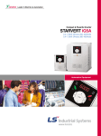
Starvert iG5
0.37- 4.0kW (0.5 - 5.4HP) 1 and
3 phase 200- 230Volts, 3 phase 380- 460Volts
Automation Equipment
Overview
Standard features
Contents
Overview
02
Features & Selection Guide
04
Specifications & Wiring
06
Terminal Configuration, Keypad & Parameter Navigation
08
Program Parameter Descriptions
10
Dimension
12
DB Resistor, Options & Peripheral Devices
14
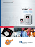
Compact iG5,
is the best for a small and cost
effective configuration.
kW / Voltage Ratings:
0.5 ~ 2HP, 200-230VAC, 1phase
0.5 ~ 5HP, 200-230VAC, 3phase
0.5 ~ 5HP, 380-460VAC, 3phase
Enclosure: IP00 ~ IP20
Inverter Type: PWM with IGBT
Control Method: Volts / Hertz with Space Vector Technology
Built-in RS-485
Built-in ModBus-RTU
Built-in PID control
Removable keypad (Able to read & write parameter)
150% torque at 0.5Hz
Trip-free operation algorithm
8 preset speeds
3 jump(skip) frequencies
3 Multifuctional inputs
1 Multifuctional output
Analog output (0~12V)
PNP and NPN dual directional signals
Speed search
3 wire operation
1 to 10 kHz carrier frequency
Built-in Braking transistor
Manual/Auto torque boost
Options
Cable for Remote Keypad Operations(2,3 and 5 meters)
DIN rail base for easy installation
Application
Converting
Fan
Pump
Food processing machine
Electric shutter
Dryer
Running machine
Overheat
Commercial washing machine
Grinder
Textile machine
Material handling machine
Centrifuge
Elevator door
Tooling machine
Conformity to global standards
UL and cUL listed for North America
CE marked for Europe
Quality process controlled by ISO9001, ISO14000
02
Overview
Standard features
Contents
Overview
02
Features & Selection Guide
04
Specifications & Wiring
06
Terminal Configuration, Keypad & Parameter Navigation
08
Program Parameter Descriptions
10
Dimension
12
DB Resistor, Options & Peripheral Devices
14
Compact iG5,
is the best for a small and cost
effective configuration.
kW / Voltage Ratings:
0.5 ~ 2HP, 200-230VAC, 1phase
0.5 ~ 5HP, 200-230VAC, 3phase
0.5 ~ 5HP, 380-460VAC, 3phase
Enclosure: IP00 ~ IP20
Inverter Type: PWM with IGBT
Control Method: Volts / Hertz with Space Vector Technology
Built-in RS-485
Built-in ModBus-RTU
Built-in PID control
Removable keypad (Able to read & write parameter)
150% torque at 0.5Hz
Trip-free operation algorithm
8 preset speeds
3 jump(skip) frequencies
3 Multifuctional inputs
1 Multifuctional output
Analog output (0~12V)
PNP and NPN dual directional signals
Speed search
3 wire operation
1 to 10 kHz carrier frequency
Built-in Braking transistor
Manual/Auto torque boost
Options
Cable for Remote Keypad Operations(2,3 and 5 meters)
DIN rail base for easy installation
Application
Converting
Fan
Pump
Food processing machine
Electric shutter
Dryer
Running machine
Overheat
Commercial washing machine
Grinder
Textile machine
Material handling machine
Centrifuge
Elevator door
Tooling machine
Conformity to global standards
UL and cUL listed for North America
CE marked for Europe
Quality process controlled by ISO9001, ISO14000
02
Starvert iG5
Features & Selection Guide
Reduced size
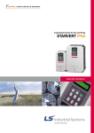
Optimum acceleration and deceleration
Enhancing its performance the iG5 shows much smaller size
compares to the previous model, the iG series.
Maximum 50% of total volume has been reduced in iG5 in order to
mount it easily on smaller control panel and DIN rail with less weight.
It allows more cost effective panel construction and system design.
To achieve a maximum torque during the acceleration and deceleration, "trip free" function is activated.
The 32-bit DSP CPU monitors the current transition during the acceleration and deceleration to program an
optimum curve that is under the trip-triggering level.
Stopped
Stopped
CH1=2V
DC 10:1
CH3=5V
DC 10:1
CH4=2V
DC 10:1
1s/div
[1s/div]
NORM:1kS/s
CH1=2V
DC 10:1
CH3=5V
DC 10:1
CH4=2V
DC 10:1
1s/div
[1s/div]
NORM:1kS/s
3
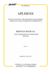
Built-in communication interface and PC monitoring software
3
The iG5 has built-in the most popular communication interfaces such as Modbus-RTU and RS232/485.
The iG5 has the small inverter features and standard medium drive features together.
The "DriveviewTM" software offers Window® based computer monitoring tool through RS485 interface with
graphic capture, keypad emulator, parameter edit and text monitor. It is applicable for all LG inverters.
Trip
=Filter=
=Offset=
=Record Length=
Smoothing : OFF Ch1 : 0.00V
BW : FULL
Ch2 : 0.00V
CH3 : 0.00V
CH4 : 0.00V
Main : 10k
Zoom : 500
=Trigger=
=Filter=
Mode : AUTO
Type : EDGE CH1
Delay : 0.0ns
Hold Off : MINIMUM
=Offset=
Smoothing : OFF Ch1 : 0.00V
BW : FULL
Ch2 : 0.00V
CH3 : 0.00V
CH4 : 0.00V
Traditional curve
RS - 485
=Record Length=
Main : 10k
Zoom : 500
=Trigger=
Mode : AUTO
Type : EDGE CH1
Delay : 0.0ns
Hold Off : MINIMUM
Optimum curve
PNP and NPN switchable duals signals
TM
ModBus-RTU
The iG5 has both PNP and NPN signals in order to controlled by PLC or outside controller.
Regardless the type of PLC or type of control signal, iG5 can work with positive 24Vdc and negative 24Vdc.
Inverter rating selection guide
Built-in PID control
It is valuable in process control. The built-in PID controller controls flow, temperature, pressure, etc.
through the proportional, integral and differential calculus between the feedback value and reference
value in closed loop.
Space vector PWM technology
The Space vector technology is being adopted in all LG drives. It features outstanding performance in its
control characteristics. It has low total harmonic distortion, low current ripple, low torque ripple, low motor
temperature rise, and better voltage utilization. It is a basic control platform of the iG5 drive. The advantages of
Space vector PWM technology are being proved in many applications.
Inverter type nomenclature
SV
Better Efficiency (Low Iron Loss in Motor)
Low Total
Harmonic Distortion
Low Motor Heat (Extended Motor)
008
iG5
-4
LG Starvert drive
High Voltage Utilization (15.9%)
Low Torque Ripple
03
Low Current Ripple
004
0.37kW
iG5
iG5 series
-1
1 phase 200~230V
Stable & Smooth Operation
008
0.75kW
iS5
iS5 series
-2
3 phase 200~230V
High and Stable Torque
015
1.5kW
iH
iH series*
-4
3 phase 380~460V
.
.
iV5
iV5 series
220
22kW
* iH drive has a different designation in kW.
04
Starvert iG5
Features & Selection Guide
Reduced size
Optimum acceleration and deceleration
Enhancing its performance the iG5 shows much smaller size
compares to the previous model, the iG series.
Maximum 50% of total volume has been reduced in iG5 in order to
mount it easily on smaller control panel and DIN rail with less weight.
It allows more cost effective panel construction and system design.
To achieve a maximum torque during the acceleration and deceleration, "trip free" function is activated.
The 32-bit DSP CPU monitors the current transition during the acceleration and deceleration to program an
optimum curve that is under the trip-triggering level.
Stopped
Stopped
CH1=2V
DC 10:1
CH3=5V
DC 10:1
CH4=2V
DC 10:1
1s/div
[1s/div]
NORM:1kS/s
CH1=2V
DC 10:1
CH3=5V
DC 10:1
CH4=2V
DC 10:1
1s/div
[1s/div]
NORM:1kS/s
3
Built-in communication interface and PC monitoring software
3
The iG5 has built-in the most popular communication interfaces such as Modbus-RTU and RS232/485.
The iG5 has the small inverter features and standard medium drive features together.
The "DriveviewTM" software offers Window® based computer monitoring tool through RS485 interface with
graphic capture, keypad emulator, parameter edit and text monitor. It is applicable for all LG inverters.
Trip
=Filter=
=Offset=
=Record Length=
Smoothing : OFF Ch1 : 0.00V
BW : FULL
Ch2 : 0.00V
CH3 : 0.00V
CH4 : 0.00V
Main : 10k
Zoom : 500
=Trigger=
=Filter=
Mode : AUTO
Type : EDGE CH1
Delay : 0.0ns
Hold Off : MINIMUM
=Offset=
Smoothing : OFF Ch1 : 0.00V
BW : FULL
Ch2 : 0.00V
CH3 : 0.00V
CH4 : 0.00V
Traditional curve
RS - 485
=Record Length=
Main : 10k
Zoom : 500
=Trigger=
Mode : AUTO
Type : EDGE CH1
Delay : 0.0ns
Hold Off : MINIMUM
Optimum curve
PNP and NPN switchable duals signals
TM
ModBus-RTU
The iG5 has both PNP and NPN signals in order to controlled by PLC or outside controller.
Regardless the type of PLC or type of control signal, iG5 can work with positive 24Vdc and negative 24Vdc.
Inverter rating selection guide
Built-in PID control
It is valuable in process control. The built-in PID controller controls flow, temperature, pressure, etc.
through the proportional, integral and differential calculus between the feedback value and reference
value in closed loop.
Space vector PWM technology
The Space vector technology is being adopted in all LG drives. It features outstanding performance in its
control characteristics. It has low total harmonic distortion, low current ripple, low torque ripple, low motor
temperature rise, and better voltage utilization. It is a basic control platform of the iG5 drive. The advantages of
Space vector PWM technology are being proved in many applications.
Inverter type nomenclature
SV
Better Efficiency (Low Iron Loss in Motor)
Low Total
Harmonic Distortion
Low Motor Heat (Extended Motor)
008
iG5
-4
LG Starvert drive
High Voltage Utilization (15.9%)
Low Torque Ripple
03
Low Current Ripple
004
0.37kW
iG5
iG5 series
-1
1 phase 200~230V
Stable & Smooth Operation
008
0.75kW
iS5
iS5 series
-2
3 phase 200~230V
High and Stable Torque
015
1.5kW
iH
iH series*
-4
3 phase 380~460V
.
.
iV5
iV5 series
220
22kW
* iH drive has a different designation in kW.
04
Starvert iG5
Specifications & Wiring
Specifications 200 ~230V Class(0.5~ 5.4 HP)
Drive Type (SV_ _ _iG5-_)
[HP]
1)
[kW]
2)
Capacity[kVA]*
FLA[A]
Output ratings
Frequency
Voltage
Voltage
Input ratings
Frequency
Weight[kg]
Braking circuit
Average braking torque
Braking torque
Max. continuous braking time
Max. duty
Cooling method
Enclosure
Motor Rating*
004-1
0.5
0.37
1.1
3
1.2
008-1
1
0.75
1.9
5
015-1
2
1.5
3
8
Wiring
004-2
0.5
0.37
1.1
3
008-2
015-2
022-2
037-2
1
2
3
5
0.75
1.5
2.2
3.7
1.9
3
4.5
6.1
5
8
12
16
0 ~ 400 Hz 3)
200 ~ 230V*
1 phase 200 ~ 230 V( 10%)
3 phase 200 ~ 230 V( 10%)
50 ~ 60 Hz ( 5%)
50 ~ 60 Hz ( 5%)
1.8
2.1
1.2
1.2
1.8
2.1
2.2
On board
20% (with optional external braking resistor : 100%, 150%)
15 seconds
0 ~ 30 % ED
Forced air cooling
Natural
Forced air cooling
IP00
040-2
5.4
4
6.5
17
2.2
Drive Type (SV_ _ _iG5-_)
1)
[HP]
[kW]
2)
Capacity[kVA]*
FLA[A]
Output ratings
Frequency
Voltage
Voltage
Input ratings
Frequency
Weight[kg]
Weight [kg]
Braking circuit
Average braking torque
Braking torque
Max. continuous braking time
Max. duty
Cooling method
Enclosure
004-4
0.5
0.37
1.1
1.1
1.7
008-4
1
0.75
1.9
2.5
015-4
2
1.5
3
4
022-4
3
2.2
4.5
6
037-4
5
3.7
6.1
8
0 ~ 400 Hz 3)
380 ~ 460V*
3 phase 380 ~ 460 V( 10%)
50 ~ 60 Hz ( 5%)
1.7
1.8
2.1
On board
20% (with optional external braking resistor : 100%, 150%)
15 seconds
0 ~ 30 % ED
Forced air cooling
IP00
040-4
5.4
4
6.5
9
Frequency setting resolution
Frequency accuracy
Control
V/F ratio
Overload capacity
Torque boost
Operation method
Input signal
Frequency setting
2.2
2.2
Operation
Output signal
Operation status
Indicator
+
Output Frequency Meter
(0 ~ 12V : pulse output)
BX
Fault Reset
RST
JOG
Multi-function Input 1
P1
Multi-function Input 2
P2
Multi-function Input 3
P3
Factory Setting
`Speed-L`
`Speed-M`
`Speed-H`
A
Common Terminal
Fault output relay
Iess than AC250V, 1A
Iess than DC30V, 1A
C
CM
B
Digital : keypad
Potentiometer
(1kohm, 1/2W)
Shield
MO
Power supply for
VR speed signal:
+12V, 100mA
0 ~ 6,000 sec, up to 8 types can be set and selected for each setting (use the multi- function terminal),
Interrupts the output of the drive
Multi-function output
Iess than DC24V, 50mA
Factory setting:`RUN`
MG
V1 Speed signal input:
0 ~10V
Jog operation
Resets fault when protective function is active
Frequency level detection, Overload alarm, stalling, overvoltage, undervoltage, drive overheating, running, stop,
I
Contact output (30A,30C,30B) - AC250V 1A, DC30V 1A
Choose 1 from output frequency, output current, output voltage, DC voltage (Output pulse: 500Hz, Output voltage: 0 ~ 10V)
Overvoltage, undervoltage, overcurrent, drive overheating, motor over heating, input/output phase loss,
FM
CM
Keypad / terminal / communication operation
Analog : 0 ~ 10V / 4 ~ 20 mA
auto restart, PID control
Speed signal input:
4 ~ 20mA(250ohm)
S+
ModBus-RTU
S-
RS-485
Communication port
CM Common for
VR, V1, I
Speed signal Input*1
input/output mis-wiring, overload protection, communication error, loss of speed command, hardware fault.
Inverter alarm
Stall prevention, overload alarm
Momentary power loss
Less than 15 msec : continuous operation, more than 15 msec : auto restart possible
Operation information
Output frequency, output current, output voltage, frequency value setting, operating speed, DC voltage
Trip information
Ambient temperature
Storage temperature
Indicates the fault when the protection function activates, memorizes up to 5 faults
-10 °C ~ 40 °C
Note) " " display main circuit terminals, " " display control circuit terminals.
1. Analog speed command can be set by Voltage, Current and both of them.
2. DB resistor is optional.
-20 °C ~ 65 °C
Ambient humidity
90 % RH max.(Non condensing)
Altitude . Vibration
Below 1,000 m ˙ below 5.9m/sec2(=0.6g)
Application site
05
W
RX
Drive gate block
DC braking, frequency limit, frequency jump, second function, slip compensation, reverse rotation prevention,
Drive trip
Environment
Reverse Run/Stop
constant speed, speed searching
Fault output
T
MOTOR
FX
Accel/Decel pattern : linear pattern, U pattern, S pattern, Optimum, Minimum
Jog
V
Manual torque boost (0 ~ 15 %), Auto torque boost
Up to 8 speeds can be set (use multi-function terminal)
Operation
function
Display
Keypad
150 % of rated current for 1 min., 200% of rated current for 0.5 sec. (characteristic is inversely proportional to time)
Multi-step
Emergency stop
S
Linear, Square pattern, User V/F
Forward, Reverse
Fault reset
Protective
function
Analog reference : 0.03 Hz / 50 Hz
Analog : 0.1% of max. output frequency
Start signal
Multi-step accel/decel time
U
FM
Forward Run/Stop
V/F control
Digital : 0.01% of max. output frequency
R
G
Jog
Digital reference : 0.01 Hz (below 100 Hz), 0.1 Hz (over 100 Hz)
B2
24
*1) Indicates the maximum applicable capacity when using 4 pole LG standard motor.
*2) Rated capacity ( 3*V*I) is based on 220V for 200V class and 440V for 400V class.
*3) Maximum output voltage will not be greater than the input voltage. Output voltage less than the input voltage can be set.
Control method
B1
MCCB
1ø 230V
or
3ø
230/460V
50/60Hz
Specifications 380 ~460V Class(0.5~ 5.4 HP)
Motor Rating*
DB Resistor*2
No corrosive gas, combustible gas, oil mist, or dust
06
Starvert iG5
Terminal Configuration, Keypad & Parameter Navigation
Power terminal configuration
Symbol
R
S
T
U
V
W
B1
B2
G
Parameter navigation
Function
AC Line input (1 phase 200~230 Vac for "-1" units 3 phase, 200~230 Vac for "-2" units and 380~460 Vac for "-4" units)
1. Drive Group
3 phase output terminals to motor
Symbol
P1, P2, P3
FX
RX
JOG
BX
Name
SET
FWD
SET
FWD
RUN
REV
RUN
REV
SET
FWD
SET
FWD
RUN
REV
RUN
REV
Descripton
Used for multi function input. Factory default is set to step frequency 1, 2, 3.
Forward run when closed and stop when opened.
Reverse run when closed and stop when opened.
Runs at jog frequency when the jog signal is on. The direction is set by the FX (or RX) signal.
Starting Contact
When the BX signal is ON, the output of the drive is cut off. When the motor uses an mechanical brake to stop,
Function Slection
BX is used to cut off the output signal. When the BX signal, which does not cut off by latching, is OFF and the
FX signal (or the RX signal) is ON, the motor keeps running, so be cautious.
RST
Fault reset
Used to release the protective status when the protective circuit is active.
CM
Sequence common
Used for the common terminal for contact input terminals.
VR
Frequency setting power(+12V)
Used as power for the analog frequency setting. Maximum output is +12V, 100mA.
Analog Frequency
V1
Frequency reference (Voltage)
Used for frequency reference and uses 0-10V for input. Input resistance is 20 kΩ
Setting
I
Frequency reference(Current)
Used for frequency reference and uses DC 4-20mA for input. Input resistance is 250Ω
CM
Frequency setting common terminal Common terminal for the analog frequency reference signal and the FM (for monitoring).
FM.CM Analog/digital output
Outputs one of the followings: output frequency, output current, output voltage, DC link voltage.
(For external monitoring)
Factory default is set to output frequency. Maximum output voltage and output current is 0-12V, 1mA.
Pulse
Output frequency is set to 500Hz.
30A, 30C, 30B Fault contact output
Activates when the protective function is operating. AC250V 1A or less, DC30V 1A or less
Fault : 30A-30C short (30B-30C open)
Nomal : 30A-30C short (30B-30C open)
Contact
MO.MG Multi-function output
Used for multi-function output
(Open collector output)
S+, SCommunication port
Communication ports for RS-485
RS232
Multi function input 1,2,3
Forward run command
Reverse run command
Jog frequency reference
Drive gate block
Output signal
Input signal
FWD
REV
External additional dynamic braking resistor connection terminals.
Chassis ground (The gound terminal("G") may be located on heat sink instead of terminal strip depend on the model name)
Control terminal configuration
Type
SET
RUN
SET
FWD
SET
FWD
RUN
REV
RUN
REV
SET
FWD
SET
FWD
RUN
REV
RUN
REV
SET
FWD
SET
FWD
RUN
REV
RUN
REV
SET
FWD
SET
FWD
RUN
REV
RUN
REV
SET
FWD
SET
FWD
RUN
REV
RUN
REV
SET
FWD
SET
FWD
RUN
REV
RUN
REV
Keypad
Class
Display
FUNC
UP
KEY
DOWN
RUN
STOP/RESET
LED
Parameter group
07
Name
Description
Press to change the parameter setting.
Up key
Press to move through codes or to increase the parameter values.
Down key
Press to move through codes or to decrease the parameter values.
Run key
Use to operate the drive
SET
STOP/RESET key
Press to stop during operation. Press to reset when a fault has occurred.
RUN
REV
Reverse run
During reverse run.
FWD
Forward run
During forward run.
SET
Setting
When the user is setting the parameters using the FUNC key
RUN
Operating
When in constant speed and blinks when accelerating or decelerating.
Group name
2. Function Group
Program key
FU I
3. I/O Group
FWD
SET
REV
RUN
FUNC
SET
RUN
Description
Drive Group
Basic parameters of Command frequency, Accel/Decel time etc.
Function 1 Group
Basic parameters of Max. Frequency, Torque boost etc.
Function 2 Group
Application parameters of Frequency jump, Frequency limit etc.
Input / Output Group
Multifunction terminal setting and Sequence operation parameters
I0
FWD
REV
FUNC
F
O
FWD
SET
REV
RUN
I
0
FWD
REV
SET
FWD
SET
FWD
RUN
REV
RUN
REV
FUNC
SET
RUN
FUNC
FU I
FWD
SET
REV
RUN
I0
FWD
REV
08
Program Parameter Descriptions
Program parameter descriptions
1. Drive Group [DRV]
Code
Code
Description
Keypad Display
DRV-00
DRV-01
DRV-02
DRV-03
Output Frequency during running, Reference Frequency during stop
Acceleration Time
Deceleration Time
Drive Mode (Run/Stop method)
0.00
ACC
DRV-04
Frequency Mode (Freq. setting method)
DRV-05
Step Frequency 1
DRV-06
DRV-07
DRV-08
DRV-09
DRV-10
DRV-11
Step Frequency 2
Step Frequency 3
Output Current
Motor Speed
DC link Voltage
User Display selection
DRV-12
DRV-13
DRV-20
DRV-21
DRV-22
Fault Display
Motor Direction set
FU1 Group selection
FU2 Group selection
I/O Group selection
,
,
Setting Range
0 to Max. Freq. (FU1-20)
0 to 6000 [sec]
0 to 6000 [sec]
0 (keypad)
1 (Keypad-2)
2 (Fx/Rx-2)
3 (ModBus-RTU)
0 [Keypad-1]
1 (Keypad-2)
2 (V1)
3 (I)
4 (V1+I)
5 (ModBus-RTU)
Starting freq (FU1-22)
to Max. freq (FU1-20)
* [A]
* [rpm]
* [V]
Selected in FU2-73
(User disp)
F (Forward) r (Reverse)
Units
Factory
Default
Adjustable
during run
0.01
0.1
0.1
-
60.00 [Hz]*
10.0 [sec]
10.0 [sec]
1
Yes
Yes
Yes
No
-
0
09
Jump to desired code #
Run Prevention
F0
F3
FU1-05
Acceleration Pattern
F5
FU1-06
Deceleration Pattern
F6
FU1-07
Stop Mode
F7
FU1-08
FU1-09
FU1-10
FU1-11
FU1-12
FU1-13
FU1-20
FU1-21
FU1-22
FU1-23
DC Injection Braking Frequency
DC Injection Braking On-delay Time
DC Injection Braking Voltage
Starting DC Injection Braking Time
Starting DC Injection Braking Voltage
Starting DC Injection Braking Time
Maximum Frequency
Base Frequency
Starting Frequency
Frequency Limit selection
F8
F9
FI0
FI I
FI2
FI3
F20
F2 I
F22
F23
FU1-24
FU1-25
FU1-26
Low Limit Frequency
High Limit Frequency
Manual/Auto Torque Boost selection
F24
F25
F26
FU1-27
FU1-28
FU1-29
Torque Boost in Forward Direction
Torque Boost in Reverse Direction
Volts/Hz Pattern
F27
F28
F29
FU1-30
FU1-31
FU1-32
FU1-33
FU1-34
FU1-35
FU1-36
FU1-37
FU1-38
FU1-39
FU1-50
User V/F - Frequency 1
User V/F - Voltage 1
User V/F - Frequency 2
User V/F - Voltage 2
User V/F - Frequency 3
User V/F - Voltage 3
User V/F - Frequency 4
User V/F - Voltage 4
Output Voltage Adjustment
Energy Save Level F39
Electronic Thermal selection
F30
F3 I
F32
F33
F34
F35
F36
F37
F38
F39
F50
FU1-51
FU1-52
FU1-53
Electronic Thermal Level for 1 minute
Electronic Thermal Level for continuous
Electronic Thermal Characteristic selection (Motor type)
F5 I
F52
F53
1 to 99
0 (None)
1 (Forward Prev)
2 (Reverse Prev)
0 (Linear)
1 (S-curve)
2 (U-curve)
3 (Minimum)
4 (Optimum)
0 (Linear)
1 (S-curve)
2 (U-curve)
3 (Minimum)
4 (Optimum)
0 (Decel)
1 (DC-brake)
2 (Free-run)
FU1-22 to 50 [Hz]
0 to 60 [sec]
0 to 200 [%]
0 to 60 [sec]
0 to 200 [%]
0 to 60 [sec]
40 to 400 [Hz]
30 to FU1-20
0.1 to 10 [Hz]
0 (No)
1 (Yes)
FU1-22 to FU1-25
FU1-24 to FU1-20
0 (Manual)
1 (Auto)
0 to 15 [%]
0 to 15 [%]
0 (Linear)
1 (Square)
2 (User V/F)
0 to FU1-32
0 to 100 [%]
FU1-30 to FU1-20
0 to 100 [%]
FU1-32 to FU1-20
0 to 100 [%]
FU1-34 to FU1-20
0 to 100 [%]
40 to 110 [%]
0 to 30 [%]
0 (No)
1 (Yes)
FU1-52 to 150 [%]
50 to FU1-51
0 (Self-cool)
1 (Forced-cool)
Keypad Display
FU1-54
FU1-55
FU1-56
Overload Warning Level
Overload Warning Hold Time
Overload Trip selection
F54
F55
F56
FU1-57
FU1-58
FU1-59
Overload Trip level
Overload Trip Delay Time
Stall Prevention Mode selection
F57
F58
F59
FU1-60
FU1-99
Stall Prevention Level
Return Code
F60
No
Setting Range
30 to 150 [%]
0 to 30 [sec]
0 (No)
1 (Yes)
30 to 200 [%]
0 to 60 [sec]
000 - 111 (bit set)
Bit 0: during Accel.
Bit 1: during Steady speed
Bit 2: during Decel.
30 to 150 [%]
Units
Factory
Default
Adjustable
during run
1
0.1
-
150 [%]
10.0 [sec]
1
Yes
Yes
Yes
1
1
bit
180 [%]
60.0 [sec]
000
Yes
1
-
150 [%]
-
No
-
1
-
Yes
Yes
Yes
-
30
0
nOn
nOn
nOn
nOn
0
0.01
0.1
-
5.00 [Hz]
0.0 [sec]
0
No
No
No
0.01
0.01
0.01
0.01
0.01
0.01
-
0.00 [Hz]
0.00 [Hz]
0.00 [Hz]
0.00 [Hz]
0.00 [Hz]
0.00 [Hz]
00
No
No
No
No
No
No
Yes
-
0
Yes
-
0
Yes
-
0000
No
1
1
1
1
0.1
-
100 [%]
100
1000
0
1.0 [sec]
Yes
Yes
Yes
Yes
Yes
No
1
0.01
1
1
1
1
1
-
4
0
3 kHz
0
No
No
No
No
No
No
Yes
No
-
0
No
1
1
1
0.01
-
3000
300
0
60.00 [Hz]*
0
Yes
Yes
Yes
Yes
No
-
1
Yes
1
0
Yes
No
3. Function Group2 [FU2]
FU2-00
FU2-01
FU2-02
FU2-03
FU2-04
FU2-05
FU2-06
Jump to desired code #
Previous Fault History 1
Previous Fault History 2
Previous Fault History 3
Previous Fault History 4
Previous Fault History 5
Erase Fault History
H0
HI
H2
H3
H4
H5
H6
Yes
FU2-07
FU2-08
FU2-10
Dwell Frequency
Dwell Time
Frequency Jump selection
H7
H8
HI0
3
0
Yes
No
FU2-11
FU2-12
FU2-13
FU2-14
FU2-15
FU2-16
FU2-19
Jump Frequency 1 Low
Jump Frequency 1 High
Jump Frequency 2 Low
Jump Frequency 2 High
Jump Frequency 3 Low
Jump Frequency 3 High
Input/Output Phase Loss Protection
HI I
HI2
HI3
HI4
HI5
HI6
HI9
0
No
FU2-20
Power ON Start selection
H20
FU2-21
Restart after Fault Reset
H2 I
FU2-22
Speed Search selection
H22
FU2-23
FU2-24
FU2-25
FU2-26
FU2-27
FU2-30
Current Limit Level during Speed Search
P Gain during Speed Search
I Gain during speed search
Number of Auto Restart Attempt
Delay Time before Auto Restart
Rated Motor selection
H23
H24
H25
H26
H27
H30
FU2-31
FU2-32
FU2-33
FU2-34
FU2-36
FU2-37
FU2-39
FU2-40
Number of Motor Poles
Rated Motor Slip
Rated Motor Current in RMS
No Load Motor Current in RMS
Motor Efficiency
Load Inertia
Carrier Frequency
Control Mode selection
H3 I
H32
H33
H34
H36
H37
H39
H40
FU2-50
PID Feedback Signal selection
H50
FU2-51
FU2-52
FU2-53
FU2-54
FU2-70
P Gain for PID Control
I Gain for PID Control
D Gain for PID Control
Limit Frequency for PID Control
Reference Frequency for Accel and Decel
H5 I
H52
H53
H54
H70
FU2-71
Accel/Decel Time Scale
H7 I
FU2-72
Power On Display
H72
Yes
0.01
10.00 [Hz]
0.01
0.01
-
20.00 [Hz]
30.00 [Hz]
- [A]
- [rpm]
- [V]
-
-
-
nOn
F
2. Function Group1[FU1]
FU1-00
FU1-03
Description
1
0
No
0
No
0.01
0.01
1
0.1
1
0.1
0.01
0.01
0.01
-
5.00 [Hz]
0.5 [sec]
50 [%]
1.0 [sec]
50 [%]
0.0 [sec]
60.00 [Hz]*
60.00 [Hz]*
0.50 [Hz]
No
No
No
No
No
No
No
No
No
No
0.01
0.01
-
0.50 [Hz]
60.00 [Hz]*
0
No
No
No
0.1
0.1
-
5.0 [%]
5.0 [%]
0
No
No
No
0.01
1
0.01
1
0.01
1
0.01
1
0.1
1
-
15.00 [Hz]*
25 [%]
30.00 [Hz]*
50 [%]
45.00 [Hz]*
75 [%]
60.00 [Hz]*
100 [%]
100[%]
0 [%]
0
No
No
No
No
No
No
No
No
No
Yes
Yes
1
1
-
150 [%]
150 [%]
0
Yes
Yes
Yes
1 to 99
-
0 (No)
1 (Yes)
0 to FU1-20
0 to 10 [sec]
0 (No)
1 (Yes)
FU1-22 to FU2-12
FU1-11 to FU2-20
FU1-22 to FU2-14
FU2-13 to FU1-20
FU1-22 to FU2-16
FU2-15 to FU1-20
00 - 11 (bit set)
Bit 0: Output phase
loss protection
Bit 1: Intput phase
loss protection
0 (No)
1 (Yes)
0 (No)
1 (Yes)
0000 - 1111 (bit set)
Bit 0: during Accel.
Bit 1: after fault reset
Bit 2: after instant power
failure restart
Bit 3: when FU2-20 is set to
1 (Yes).
80 to 200 [%]
0 to 9999
0 to 9999
0 to 10
0 to 60 [sec]
0.4 (0.37kW) 0.8 (0.75kW)
1.5 (1.5kW) 2.2 (2.2kW)
2 to 12
0 to 10 [Hz]
0.1 to 99.9 [A]
0.1 to 99.9 [A]
50 to 100 [%]
0 to 2
1 to 10 [kHz]
0 (V/F)
1 (Slip Compen)
2 (PID)
0 (I)
1 (V1)
0 to 9999
0 to 9999
0 to 9999
0 to FU1-20
0 (Max Freq)
1 (Delta Freq)
0 (0.01 sec)
1 (0.1 sec)
2 (1 sec)
0 (Cmd. Freq) 1 (Acc. Time)
2 (Dec. Time) 3 (Drv mode)
4 (Freq mode) 5 (Step Freq 1)
6 (Step Freq 2) 7 (Step Freq 3)
8 (Current) 9 (Speed)
10(DC link Vtg) 11 (User disp)
12 (Fault Display)
13 (Motor direction)
Yes
Yes
10
Starvert iG5
Keypad Display
FU2-73
User Display selection
H73
FU2-74
FU2-75
Gain for Motor Speed Display
DB(Dynamic Braking)Resistor
Mode selection
H74
H75
FU2-76
FU2-79
FU2-81
FU2-82
FU2-83
FU2-84
Duty of Dynamic Braking Resistor
Software Version
2nd Acceleration Time
2nd Deceleration Time
2nd Base Frequency
2nd V/F Pattern
H76
H79
H8 I
H82
H83
H84
FU2-85
FU2-86
FU2-87
FU2-88
FU2-89
FU2-90
FU2-91
2nd Forward Torque Boost
2nd Reverse Torque Boost
2nd Stall Prevention Level
2nd Electronic Thermal Level for 1 minute
2nd Electronic Thermal Level for continuous
2nd Rated Motor Current
Read Parameters into Keypad from Inverter
H85
H86
H87
H88
H89
H90
H9 I
FU2-92
Write Parameters to Inverter from Keypad
H92
FU2-93
Initialize Parameter
H93
FU2-94
FU2-99
Parameter Write Protection
Return Code
H94
Setting Range
0 (Voltage)
1 (Watt)
2 (Torque)
1 to 1000 [%]
0 [None]
1 [None]
2 (Ext.DB-R)
0 to 30 [%]
0 to 6000 [sec]
0 to 6000 [sec]
30 to FU1-20
0 (Linear)
1 (Square)
2 (User V/F)
0 to 15 [%]
0 to 15 [%]
30 to 150 [%]
FU2-89 to 150 [%]
50 to FU2-88(maximum 150%)
0.1 to 99.9 [A]
0 (No)
1 (Yes)
0 (No)
1 (Yes)
0 (No)
1 (All Groups)
2 (DRV)
3 (FU1)
4 (FU2)
5 (I/O)
0 to 255
Units
Factory
Default
Adjustable
during run
-
0
Yes
1
-
100 [%]
0
Yes
Yes
1
0.1
0.1
0.01
-
10 [%]
. E
5.0 [sec]
10.0 [sec]
60.00 [Hz]*
0
Yes
Yes
Yes
No
No
0.1
0.1
1
1
1
0.1
-
5.0 [%]
5.0 [%]
150 [%]
150 [%]
100 [%]
1.8 [A]
0
No
No
No
Yes
Yes
No
No
-
0
No
-
0
No
1
-
0
1
Yes
Yes
4.Input / Output Group [I/0]
Keypad Display
I/O-00
I/O-01
I/O-02
I/O-03
I/O-04
I/O-05
I/O-06
I/O-07
I/O-08
I/O-09
I/O-10
I/O-11
Jump to desired code #
Filtering Time Constant for V1 Signal Input
V1 Input Minimum Voltage
Frequency corresponding to V1 Input Minimum Voltage
V1 Input Maximum Voltage
Frequency corresponding to V1 Input Maximum Voltage
Filtering Time Constant for I Signal Input
I Input Minimum Current
Frequency corresponding to I Input Minimum Current
I Input Maximum Current
Frequency corresponding to I Input Maximum Current
Criteria for Analog Input Signal Loss
I
I
I
I
I
I
I
I
I
I
I
I
I/O-12
Multi-function Input Terminal 'P1' define
8,9, 15, 20, 21, 22, 23, 24, 25, 26(-Reserved-)
I I2
I
I
I
I
I
I
I
I
I
I
I
I
I
I
I
I
I3
I4
I5
I6
I7
20
2I
22
23
24
25
26
27
28
29
30
Factory
Default
Acceleration Time 4
Deceleration Time 4
Acceleration Time 5
Deceleration Time 5
Acceleration Time 6
Deceleration Time 6
Acceleration Time 7
Deceleration Time 7
FM (Frequency Meter) Output selection
I
I
I
I
I
I
I
I
I
3I
32
33
34
35
36
37
38
40
I/O-41
I/O-42
I/O-43
I/O-44
FM Output Adjustment
Frequency Detection Level
Frquency Detection Bandwidth
Multi-function Output define (MO)15, 16, 18, 19, 20(-Reserved-)
I
I
I
I
4I
42
43
44
I/O-45
Fault Output Relay setting (30A, 30B, 30C)
I 45
I/O-46
I/O-47
Inverter Number
Baud Rate I47
I 46
I 47
I/O-48
Operating selection at Loss of Freq. Reference
I 48
I/O-49
I/O-50
Waiting Time after Loss of Freq. Reference
Communication Protocol selection
I 49
I 50
I/O-99
Return Code
Adjustable
during run
1
1
0.01
0.01
0.01
0.01
1
0.01
0.01
0.01
0.01
-
1
1,000 [ms]
0.00 [V]
0.00 [Hz]
10.00 [V]
60.00 [Hz]*
1,000 [ms]
4.00 [mA]
0.00 [Hz]
20.00 [mA]
60.00 [Hz]*
0
Yes
Yes
Yes
Yes
Yes
Yes
Yes
Yes
Yes
Yes
Yes
Yes
-
0
No
Factory
Default
Adjustable
during run
Setting Range
Units
0 to 6000 [sec]
0 to 6000 [sec]
0 to 6000 [sec]
0 to 6000 [sec]
0 to 6000 [sec]
0 to 6000 [sec]
0 to 6000 [sec]
0 to 6000 [sec]
0 (Frequency)
1 (Current)
2 (Voltage)
3 (DC link Vtg)
10 to 200 [%]
0 to FU1-20
0 to FU1-20
0 (FDT-1)
1 (FDT-2)
2 (FDT-3)
3 (FDT-4)
4 (FDT-5)
5 (IOL)
6 (IOL)
7 (Stall)
8 (OV)
9 (LV)
10 (OH)
11 (Lost Command)
12 (Run)
13 (Stop)
14 (Steady)
17 (Search)
000 - 111 (bit set)
Bit 0: LV Bit 1: All Trip
Bit 2: Auto retry
1 to 32
0 (1200 bps)
1 (2400 bps)
2 (4800 bps)
3 (9600 bps)
4 (19200 bps)
0 (None)
1 (FreeRun)
2 (Stop)
0.1 to 120 [sec]
0 (LG- BUS)
1~6(ModbusASCII)
7~9 (Modbus-RTU)
0.1
0.1
0.1
0.1
0.1
0.1
0.1
0.1
-
50.0 [sec]
50.0 [sec]
40.0 [sec]
40.0 [sec]
30.0 [sec]
30.0 [sec]
20.0 [sec]
20.0 [sec]
0
Yes
Yes
Yes
Yes
Yes
Yes
Yes
Yes
Yes
1
0.01
0.01
-
100 [%]
30.00 [Hz]
10.00 [Hz]
12
Yes
Yes
Yes
Yes
-
010
Yes
1
-
1
3
Yes
Yes
-
0
Yes
0.1
1.0 [sec]
7
Yes
Yes
-
1
Yes
Note: Parameters that are set by bit are ON (1) when the upper LED is lit. (F59, H19, H22, I15, I16, I45 are the parameters that are set by bit.)
Note: *marked default value changes depend on the main frequency setting in factory(50 / 60Hz)
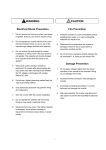
Dimension : mm(inch)
4.5
iG5
VARIABLE FREQUENCY DRIVER
00.00
FUNC
RUN
STOP
RESET
CAUTION
Read the manual and follow the safety instruction before installation or operation
Do not the power supply to the drive output terminal (U, V, W)
Before opening the cover, disconnect all power and wait at least 3 minutes untill DC
SV015IG5-2
Multi-function Input Terminal 'P2' define
Multi-function Input Terminal 'P3' define
Terminal Input Status
Terminal Output Status
Filtering Time Constant for Multi-function Input Terminals
Jog Frequency setting
Step Frequency 4
Step Frequency 5
Step Frequency 6
Step Frequency 7
Acceleration Time 1 for Step Frequency
Deceleration Time 1 for Step Frequency
Acceleration Time 2
Deceleration Time 2
Acceleration Time 3
Deceleration Time 3
1 to 99
0 to 9999 [ms]
0 to I/O-04
0 to FU1-20
I/O-02 to 10 [V]
0 to FU1-20
0 to 9999 [ms]
0 to I/O-09
0 to FU1-20
I/O-07 to 20 [mA]
0 to FU1-20
0 (None)
1 (Half of x1)
2 (Below x1)
0 (Speed-L)
1 (Speed-M)
2 (Speed-H)
3 (XCEL-L)
4 (XCEL-M)
5 (XCEL-H)
6 (Dc-brake)
7 (2nd Func)
10 (Up)
11 (Down)
12 (3-Wire)
13 (Ext trip-A)
14 (Ext trip-B)
16 (Open-loop)
17 (Main-drive)
18 (Analog hold)
19 (XCEL stop)
Same as above
Same as above
00000000 - 11111111 (bit set)
0 - 1 (bit set)
2 to 50
FU1-22 to FU1-20
FU1-22 to FU1-20
FU1-22 to FU1-20
FU1-22 to FU1-20
FU1-22 to FU1-20
0 to 6000 [sec]
0 to 6000 [sec]
0 to 6000 [sec]
0 to 6000 [sec]
0 to 6000 [sec]
0 to 6000 [sec]
Units
I/O-31
I/O-32
I/O-33
I/O-34
I/O-35
I/O-36
I/O-37
I/O-38
I/O-40
International system Co, Ltd Made In Korea
I/O-13
I/O-14
I/O-15
I/O-16
I/O-17
I/O-20
I/O-21
I/O-22
I/O-23
I/O-24
I/O-25
I/O-26
I/O-27
I/O-28
I/O-29
I/O-30
0
I
2
3
4
5
6
7
8
9
I0
II
Setting Range
Keypad Display
SOURCE AC200-230V 50/60Hz
OUTPUT CAPACITY 1.5kVA
CURRENT 5A
FRCQUENCY 0.2-400Hz
11
Description
Description
bus capacitors discharge.
`Risk of Electric Shock`-more than one disconnect switch is required to de energize the equipment before servicing.
4
Code
Code
H2
Description
4.5
4.5
W2
W1
1
0.01
0.01
0.01
0.01
0.1
0.1
0.1
0.1
0.1
0.1
0.1
1
2
15
10.00 [Hz]
40.00 [Hz]
50.00 [Hz]
40.00 [Hz]
30.00 [Hz]
20.0 [sec]
20.0 [sec]
30.0 [sec]
30.0 [sec]
40.0 [sec]
40.0 [sec]
No
No
Yes
Yes
Yes
Yes
Yes
Yes
Yes
Yes
Yes
Yes
Yes
Yes
Inverter
D1
Code
Dimension
SV004iG5-1
SV004iG5-2
SV008iG5-1
SV008iG5-2
SV015iG5-1
SV015iG5-2
SV022iG5-2
SV037iG5-2
SV040iG5-2
SV004iG5-4
SV008iG5-4
SV015iG5-4
SV022iG5-4
SV037iG5-4
SV040iG5-4
HP
0.5
0.5
1
1
2
2
3
5
5.4
0.5
1
2
3
5
5.4
W1
W2
H1
100(3.94)
100(3.94)
130(5.12)
100(3.94)
150(5.90)
130(5.12)
150(5.90)
150(5.90)
150(5.90)
130(5.12)
130(5.12)
130(5.12)
150(5.90)
150(5.90)
150(5.90)
88(3.46)
88(3.46)
118(4.65)
88(3.46)
138(5.43)
118(4.65)
138(5.43)
138(5.43)
138(5.43)
118(4.65)
118(4.65)
118(4.65)
138(5.43)
138(5.43)
138(5.43)
128(5.04)
128(5.04)
128(5.04)
128(5.04)
128(5.04)
128(5.04)
128(5.04)
128(5.04)
128(5.04)
128(5.04)
128(5.04)
128(5.04)
128(5.04)
128(5.04)
128(5.04)
H2
117.5(4.63)
117.5(4.63)
117.5(4.63)
117.5(4.63)
117.5(4.63)
117.5(4.63)
117.5(4.63)
117.5(4.63)
117.5(4.63)
117.5(4.63)
117.5(4.63)
117.5(4.63)
117.5(4.63)
117.5(4.63)
117.5(4.63)
D1
130.9(5.15)
130.9(5.15)
150.9(5.94)
130.9(5.15)
155(6.10)
150.9(5.94)
155(6.10)
155(6.10)
155(6.10)
150.9(5.94)
150.9(5.94)
150.9(5.94)
155(6.10)
155(6.10)
155(6.10)
12
Starvert iG5
Keypad Display
FU2-73
User Display selection
H73
FU2-74
FU2-75
Gain for Motor Speed Display
DB(Dynamic Braking)Resistor
Mode selection
H74
H75
FU2-76
FU2-79
FU2-81
FU2-82
FU2-83
FU2-84
Duty of Dynamic Braking Resistor
Software Version
2nd Acceleration Time
2nd Deceleration Time
2nd Base Frequency
2nd V/F Pattern
H76
H79
H8 I
H82
H83
H84
FU2-85
FU2-86
FU2-87
FU2-88
FU2-89
FU2-90
FU2-91
2nd Forward Torque Boost
2nd Reverse Torque Boost
2nd Stall Prevention Level
2nd Electronic Thermal Level for 1 minute
2nd Electronic Thermal Level for continuous
2nd Rated Motor Current
Read Parameters into Keypad from Inverter
H85
H86
H87
H88
H89
H90
H9 I
FU2-92
Write Parameters to Inverter from Keypad
H92
FU2-93
Initialize Parameter
H93
FU2-94
FU2-99
Parameter Write Protection
Return Code
H94
Setting Range
0 (Voltage)
1 (Watt)
2 (Torque)
1 to 1000 [%]
0 [None]
1 [None]
2 (Ext.DB-R)
0 to 30 [%]
0 to 6000 [sec]
0 to 6000 [sec]
30 to FU1-20
0 (Linear)
1 (Square)
2 (User V/F)
0 to 15 [%]
0 to 15 [%]
30 to 150 [%]
FU2-89 to 150 [%]
50 to FU2-88(maximum 150%)
0.1 to 99.9 [A]
0 (No)
1 (Yes)
0 (No)
1 (Yes)
0 (No)
1 (All Groups)
2 (DRV)
3 (FU1)
4 (FU2)
5 (I/O)
0 to 255
Units
Factory
Default
Adjustable
during run
-
0
Yes
1
-
100 [%]
0
Yes
Yes
1
0.1
0.1
0.01
-
10 [%]
. E
5.0 [sec]
10.0 [sec]
60.00 [Hz]*
0
Yes
Yes
Yes
No
No
0.1
0.1
1
1
1
0.1
-
5.0 [%]
5.0 [%]
150 [%]
150 [%]
100 [%]
1.8 [A]
0
No
No
No
Yes
Yes
No
No
-
0
No
-
0
No
1
-
0
1
Yes
Yes
4.Input / Output Group [I/0]
Keypad Display
I/O-00
I/O-01
I/O-02
I/O-03
I/O-04
I/O-05
I/O-06
I/O-07
I/O-08
I/O-09
I/O-10
I/O-11
Jump to desired code #
Filtering Time Constant for V1 Signal Input
V1 Input Minimum Voltage
Frequency corresponding to V1 Input Minimum Voltage
V1 Input Maximum Voltage
Frequency corresponding to V1 Input Maximum Voltage
Filtering Time Constant for I Signal Input
I Input Minimum Current
Frequency corresponding to I Input Minimum Current
I Input Maximum Current
Frequency corresponding to I Input Maximum Current
Criteria for Analog Input Signal Loss
I
I
I
I
I
I
I
I
I
I
I
I
I/O-12
Multi-function Input Terminal 'P1' define
8,9, 15, 20, 21, 22, 23, 24, 25, 26(-Reserved-)
I I2
I
I
I
I
I
I
I
I
I
I
I
I
I
I
I
I
I3
I4
I5
I6
I7
20
2I
22
23
24
25
26
27
28
29
30
Factory
Default
Acceleration Time 4
Deceleration Time 4
Acceleration Time 5
Deceleration Time 5
Acceleration Time 6
Deceleration Time 6
Acceleration Time 7
Deceleration Time 7
FM (Frequency Meter) Output selection
I
I
I
I
I
I
I
I
I
3I
32
33
34
35
36
37
38
40
I/O-41
I/O-42
I/O-43
I/O-44
FM Output Adjustment
Frequency Detection Level
Frquency Detection Bandwidth
Multi-function Output define (MO)15, 16, 18, 19, 20(-Reserved-)
I
I
I
I
4I
42
43
44
I/O-45
Fault Output Relay setting (30A, 30B, 30C)
I 45
I/O-46
I/O-47
Inverter Number
Baud Rate I47
I 46
I 47
I/O-48
Operating selection at Loss of Freq. Reference
I 48
I/O-49
I/O-50
Waiting Time after Loss of Freq. Reference
Communication Protocol selection
I 49
I 50
I/O-99
Return Code
Adjustable
during run
1
1
0.01
0.01
0.01
0.01
1
0.01
0.01
0.01
0.01
-
1
1,000 [ms]
0.00 [V]
0.00 [Hz]
10.00 [V]
60.00 [Hz]*
1,000 [ms]
4.00 [mA]
0.00 [Hz]
20.00 [mA]
60.00 [Hz]*
0
Yes
Yes
Yes
Yes
Yes
Yes
Yes
Yes
Yes
Yes
Yes
Yes
-
0
No
Factory
Default
Adjustable
during run
Setting Range
Units
0 to 6000 [sec]
0 to 6000 [sec]
0 to 6000 [sec]
0 to 6000 [sec]
0 to 6000 [sec]
0 to 6000 [sec]
0 to 6000 [sec]
0 to 6000 [sec]
0 (Frequency)
1 (Current)
2 (Voltage)
3 (DC link Vtg)
10 to 200 [%]
0 to FU1-20
0 to FU1-20
0 (FDT-1)
1 (FDT-2)
2 (FDT-3)
3 (FDT-4)
4 (FDT-5)
5 (IOL)
6 (IOL)
7 (Stall)
8 (OV)
9 (LV)
10 (OH)
11 (Lost Command)
12 (Run)
13 (Stop)
14 (Steady)
17 (Search)
000 - 111 (bit set)
Bit 0: LV Bit 1: All Trip
Bit 2: Auto retry
1 to 32
0 (1200 bps)
1 (2400 bps)
2 (4800 bps)
3 (9600 bps)
4 (19200 bps)
0 (None)
1 (FreeRun)
2 (Stop)
0.1 to 120 [sec]
0 (LG- BUS)
1~6(ModbusASCII)
7~9 (Modbus-RTU)
0.1
0.1
0.1
0.1
0.1
0.1
0.1
0.1
-
50.0 [sec]
50.0 [sec]
40.0 [sec]
40.0 [sec]
30.0 [sec]
30.0 [sec]
20.0 [sec]
20.0 [sec]
0
Yes
Yes
Yes
Yes
Yes
Yes
Yes
Yes
Yes
1
0.01
0.01
-
100 [%]
30.00 [Hz]
10.00 [Hz]
12
Yes
Yes
Yes
Yes
-
010
Yes
1
-
1
3
Yes
Yes
-
0
Yes
0.1
1.0 [sec]
7
Yes
Yes
-
1
Yes
Note: Parameters that are set by bit are ON (1) when the upper LED is lit. (F59, H19, H22, I15, I16, I45 are the parameters that are set by bit.)
Note: *marked default value changes depend on the main frequency setting in factory(50 / 60Hz)
Dimension : mm(inch)
4.5
iG5
VARIABLE FREQUENCY DRIVER
00.00
FUNC
RUN
STOP
RESET
CAUTION
Read the manual and follow the safety instruction before installation or operation
Do not the power supply to the drive output terminal (U, V, W)
Before opening the cover, disconnect all power and wait at least 3 minutes untill DC
SV015IG5-2
Multi-function Input Terminal 'P2' define
Multi-function Input Terminal 'P3' define
Terminal Input Status
Terminal Output Status
Filtering Time Constant for Multi-function Input Terminals
Jog Frequency setting
Step Frequency 4
Step Frequency 5
Step Frequency 6
Step Frequency 7
Acceleration Time 1 for Step Frequency
Deceleration Time 1 for Step Frequency
Acceleration Time 2
Deceleration Time 2
Acceleration Time 3
Deceleration Time 3
1 to 99
0 to 9999 [ms]
0 to I/O-04
0 to FU1-20
I/O-02 to 10 [V]
0 to FU1-20
0 to 9999 [ms]
0 to I/O-09
0 to FU1-20
I/O-07 to 20 [mA]
0 to FU1-20
0 (None)
1 (Half of x1)
2 (Below x1)
0 (Speed-L)
1 (Speed-M)
2 (Speed-H)
3 (XCEL-L)
4 (XCEL-M)
5 (XCEL-H)
6 (Dc-brake)
7 (2nd Func)
10 (Up)
11 (Down)
12 (3-Wire)
13 (Ext trip-A)
14 (Ext trip-B)
16 (Open-loop)
17 (Main-drive)
18 (Analog hold)
19 (XCEL stop)
Same as above
Same as above
00000000 - 11111111 (bit set)
0 - 1 (bit set)
2 to 50
FU1-22 to FU1-20
FU1-22 to FU1-20
FU1-22 to FU1-20
FU1-22 to FU1-20
FU1-22 to FU1-20
0 to 6000 [sec]
0 to 6000 [sec]
0 to 6000 [sec]
0 to 6000 [sec]
0 to 6000 [sec]
0 to 6000 [sec]
Units
I/O-31
I/O-32
I/O-33
I/O-34
I/O-35
I/O-36
I/O-37
I/O-38
I/O-40
International system Co, Ltd Made In Korea
I/O-13
I/O-14
I/O-15
I/O-16
I/O-17
I/O-20
I/O-21
I/O-22
I/O-23
I/O-24
I/O-25
I/O-26
I/O-27
I/O-28
I/O-29
I/O-30
0
I
2
3
4
5
6
7
8
9
I0
II
Setting Range
Keypad Display
SOURCE AC200-230V 50/60Hz
OUTPUT CAPACITY 1.5kVA
CURRENT 5A
FRCQUENCY 0.2-400Hz
11
Description
Description
bus capacitors discharge.
`Risk of Electric Shock`-more than one disconnect switch is required to de energize the equipment before servicing.
4
Code
Code
H2
Description
4.5
4.5
W2
W1
1
0.01
0.01
0.01
0.01
0.1
0.1
0.1
0.1
0.1
0.1
0.1
1
2
15
10.00 [Hz]
40.00 [Hz]
50.00 [Hz]
40.00 [Hz]
30.00 [Hz]
20.0 [sec]
20.0 [sec]
30.0 [sec]
30.0 [sec]
40.0 [sec]
40.0 [sec]
No
No
Yes
Yes
Yes
Yes
Yes
Yes
Yes
Yes
Yes
Yes
Yes
Yes
Inverter
D1
Code
Dimension
SV004iG5-1
SV004iG5-2
SV008iG5-1
SV008iG5-2
SV015iG5-1
SV015iG5-2
SV022iG5-2
SV037iG5-2
SV040iG5-2
SV004iG5-4
SV008iG5-4
SV015iG5-4
SV022iG5-4
SV037iG5-4
SV040iG5-4
HP
0.5
0.5
1
1
2
2
3
5
5.4
0.5
1
2
3
5
5.4
W1
W2
H1
100(3.94)
100(3.94)
130(5.12)
100(3.94)
150(5.90)
130(5.12)
150(5.90)
150(5.90)
150(5.90)
130(5.12)
130(5.12)
130(5.12)
150(5.90)
150(5.90)
150(5.90)
88(3.46)
88(3.46)
118(4.65)
88(3.46)
138(5.43)
118(4.65)
138(5.43)
138(5.43)
138(5.43)
118(4.65)
118(4.65)
118(4.65)
138(5.43)
138(5.43)
138(5.43)
128(5.04)
128(5.04)
128(5.04)
128(5.04)
128(5.04)
128(5.04)
128(5.04)
128(5.04)
128(5.04)
128(5.04)
128(5.04)
128(5.04)
128(5.04)
128(5.04)
128(5.04)
H2
117.5(4.63)
117.5(4.63)
117.5(4.63)
117.5(4.63)
117.5(4.63)
117.5(4.63)
117.5(4.63)
117.5(4.63)
117.5(4.63)
117.5(4.63)
117.5(4.63)
117.5(4.63)
117.5(4.63)
117.5(4.63)
117.5(4.63)
D1
130.9(5.15)
130.9(5.15)
150.9(5.94)
130.9(5.15)
155(6.10)
150.9(5.94)
155(6.10)
155(6.10)
155(6.10)
150.9(5.94)
150.9(5.94)
150.9(5.94)
155(6.10)
155(6.10)
155(6.10)
12
Starvert iG5
DB Resistor, Options & Peripheral Devices
RFI Filters
Dynamic Braking(DB) Resistors
1. Standard application
IG5 Series
100
100
100
100
100
100
100
100
100
100
100
100
100
100
100
400
200
100
400
200
100
60
40
40
1800
900
450
300
200
200
Average braking
torque[%]
Enable duty[%]
Continuous
braking time[sec]
100
100
100
100
100
100
100
100
100
100
100
100
100
100
100
5
5
3
5
5
3
2
2
2
5
5
3
2
2
2
5
5
5
5
5
5
5
5
5
5
5
5
5
5
5
Average braking
torque[%]
Enable duty[%]
Continuous
braking time[sec]
100
100
100
100
100
100
100
100
100
100
100
100
100
100
100
5
5
5
5
5
5
5
5
5
5
5
5
5
5
5
5
5
5
5
5
5
5
5
5
5
5
5
5
5
5
Average braking
torque[%]
Enable duty[%]
Continuous
braking time[sec]
150
150
150
150
150
150
150
150
150
150
150
150
150
150
150
5
5
5
5
5
5
5
5
5
5
5
5
5
5
5
5
5
5
5
5
5
5
5
5
5
5
5
5
5
5
Drive Models
SINGLE PHASE
SV004iG5-1
SV008iG5-1
SV015iG5-1
THREE PHASE
SV004iG5-2
SV008iG5-2
SV015iG5-2
SV022iG5-2
SV037iG5-2
SV040iG5-2
SV004iG5-4
SV008iG5-4
SV015iG5-4
SV022iG5-4
SV037iG5-4
SV040iG5-4
2. When the braking magnitude is high
Resistor capacity
[W]
Drive
SV004iG5-1
SV008iG5-1
SV015iG5-1
SV004iG5-2
SV008iG5-2
SV015iG5-2
SV022iG5-2
SV037iG5-2
SV040iG5-2
SV004iG5-4
SV008iG5-4
SV015iG5-4
SV022iG5-4
SV037iG5-4
SV040iG5-4
Resistor value[Ω]
100
100
200
100
100
200
300
500
500
100
100
200
300
500
500
400
200
100
400
200
100
60
40
40
1800
900
450
300
200
200
Resistor capacity
[W]
Drive
SV004iG5-1
SV008iG5-1
SV015iG5-1
SV004iG5-2
SV008iG5-2
SV015iG5-2
SV022iG5-2
SV037iG5-2
SV040iG5-2
SV004iG5-4
SV008iG5-4
SV015iG5-4
SV022iG5-4
SV037iG5-4
SV040iG5-4
Resistor value[Ω]
150
150
300
150
150
300
400
600
600
150
150
300
400
600
600
300
150
60
300
150
60
50
33
33
1200
600
300
200
130
130
Options
Code
Current
10A
11A
20A
(max.)
250VA
250VA
250VA
(max.)
FFG5-T005-1
5A
FFG5-T012-1
12A
0.4kW
0.8kW
1.5kW
FFG5-M010-1
FFG5-M011-1
FFG5-M020-1
0.4kW
0.8kW
1.5kW
2.2kW
3.7kW
4.0kW
0.4kW
0.8kW
1.5kW
2.2kW
3.7kW
4.0kW
Drive Models
SINGLE PHASE
SV004iG5-1
SV008iG5-1
SV015iG5-1
THREE PHASE
SV004iG5-2
SV008iG5-2
SV015iG5-2
SV022iG5-2
SV037iG5-2
SV040iG5-2
SV004iG5-4
SV008iG5-4
SV015iG5-4
SV022iG5-4
SV037iG5-4
SV040iG5-4
Leakage
Current
2 meter, 3 meter and 5 meter cable and mounting fixture.
Mount
Output
Chokes
159.5 X 80
159.5 X 110
159.5 X 130
M4
M4
M4
FS-1
FS-1
FS-2
Weight
250VA
0.3A 18A
173.5 X 103.5 X 40
159.5 X 80
M4
FS-1
250VA
0.3A 18A
173.5 X 133.5 X 40
159.5 X 110
M4
FS-2
FS-2
FFG5-T020-1
20A
250VA
0.3A 18A
173.5 X 153.5 X 40
159.5 X 130
M4
FFG5-T006-1
6A
380VAC
0.5A 27A
173.5 X 133.5 X 40
159.5 X 110
M4
FS-1
FFG5-T011-1
11A
380VAC
0.5A 27A
173.5 X 133.5 X 40
159.5 X 130
M4
FS-2
Mount
Output
Chokes
Standard Filter
Power
Code
Current
Tension
Voltage
Leakage
Current
Dimensions
LWH
Mounting
YX
Weight
(max.)
0.4kW
0.8kW
1.5kW
FEG5-T010-(X)
10A
250VA
3.5A
150.5 X 55 X 45
140 X 45
---
FS-1
FEG5-T015-(X)
15A
250VA
(max.)
3.5A
150.5 X 55 X 45
140 X 45
---
FS-2
0.4kW
0.8kW
1.5kW
2.2kW
3.7kW
4.0kW
0.4kW
0.8kW
1.5kW
2.2kW
3.7kW
4.0kW
FEG5-T006-(X)
6A
250VA
0.3A 18A
250 X 110 X 60
238 X 76
---
FS-2
FEG5-T012-(X)
12A
250VA
0.3A 18A
250 X 110 X 60
238 X 76
---
FS-2
FEG5-T020-(X)
20A
250VA
0.3A 18A
270 X 140 X 60
258 X 106
---
FS-2
FEG5-T006-(X)
6A
380VAC
0.5A 27A
250 X 110 X 60
238 X 76
---
FS-2
FEG5-T012-(X)
12A
380VAC
0.5A 27A
250 X 110 X 60
238 X 76
---
FS-2
(X) (1) Industrial environment EN 50081-1 (A class)
(2) Domestic and industrial environment EN 50081-1 (B class)
FF Series (Footprint)
FE Series (Standard)
FS Series (output chokes)
H
D H
H
Y
Y
Y
X
W
X
Din rail mounting plate
Remote keypad mounting fixture and cable
Mounting
YX
173.5 X 103.5 X 40
173.5 X 133.5 X 40
173.5 X 153.5 X 40
Description
DIN Rail base
Dimensions
LWH
3.5A
3.5A
3.5A
IG5 Series
W
Option
Power
CARGA
SV004iG5-1
SV008iG5-1
SV015iG5-1
SV004iG5-2
SV008iG5-2
SV015iG5-2
SV022iG5-2
SV037iG5-2
SV040iG5-2
SV004iG5-4
SV008iG5-4
SV015iG5-4
SV022iG5-4
SV037iG5-4
SV040iG5-4
Resistor value[Ω]
RED
Resistor capacity
[W]
Drive
Footprint Filter
Tension
Voltage
L
L
X
W
Type
D
W
H
X
O
FS-1
21
85
46
70
5
FS-2
28.5
105
62
90
5
FS-3
48
150
110
125 x 30
5
FS-4
58
200
170
180 x 45
5
Peripheral devices
13
Drive Models
kW
MCCB, ELB
Magnetic Contactor
SV004iG5-1
SV008iG5-1
SV015iG5-1
SV004iG5-2
SV008iG5-2
SV015iG5-2
SV022iG5-2
SV037iG5-2
SV040iG5-2
SV004iG5-4
SV008iG5-4
SV015iG5-4
SV022iG5-4
SV037iG5-4
SV040iG5-4
0.37
0.75
1.5
0.37
0.75
1.5
2.2
3.7
4
0.37
0.75
1.5
2.2
3.7
4
ABS33a, EBS33
ABS33a, EBS33
ABS33a, EBS33
ABS33a, EBS33
ABS33a, EBS33
ABS33a, EBS33
ABS33a, EBS33
ABS33a, EBS33
ABS33a, EBS33
ABS33a, EBS33
ABS33a, EBS33
ABS33a, EBS33
ABS33a, EBS33
ABS33a, EBS33
ABS33a, EBS33
SMC-10P
SMC-10P
SMC-10P
SMC-10P
SMC-10P
SMC-10P
SMC-15P
SMC-20P
SMC-20P
SMC-10P
SMC-10P
SMC-10P
SMC-20P
SMC-20P
SMC-20P
R,S,T
2(14)
2(14)
2(14)
2(14)
2(14)
2(14)
2(14)
3.5(12)
3.5(12)
2(14)
2(14)
2(14)
2(14)
2(14)
2(14)
Wire, mm2(AWG)
U,V,W
Ground
2(14)
2(14)
2(14)
2(14)
2(14)
2(14)
2(14)
3.5(12)
3.5(12)
2(14)
2(14)
2(14)
2(14)
2(14)
2(14)
3.5(12)
3.5(12)
3.5(12)
3.5(12)
3.5(12)
3.5(12)
3.5(12)
3.5(12)
3.5(12)
2(14)
2(14)
2(14)
2(14)
2(14)
2(14)
AC
Input
AC Reactor
DC Reactor
10A
10A
10A
10A
10A
15A
25A
40A
40A
6A
6A
10A
10A
20A
20A
2.13mH, 5.7A
2.13mH, 5.7A
2.13mH, 5.7A
2.13mH, 5.7A
2.13mH, 5.7A
1.20mH, 10A
0.88mH, 14A
0.56mH, 20A
0.56mH, 20A
8.63mH, 2.8A
8.63mH, 2.8A
4.81mH, 4.8A
3.23mH, 7.5A
2.34mH, 10A
2.34mH, 10A
7.00mH, 5.4A
7.00mH, 5.4A
7.00mH, 5.4A
7.00mH, 5.4A
7.00mH, 5.4A
4.05mH, 9.2A
2.92mH, 13A
1.98mH, 19A
1.98mH, 19A
28.62mH, 2.7A
28.62mH, 2.7A
16.14mH, 4.6A
11.66mH, 7.1A
7.83mH, 10A
7.83mH, 10A
INVERTER
SHIELDED CABLE
FF Series (Footprint)
MOTOR
FILTER
FE Series (Standard)
INVERTER
FILTER
SHIELDED CABLE
MOTOR
14
iG5표지 2005.3.312:47PM 페이지1
Leader in Electrics & Automation
� For your safety, please read user's manual thoroughly before operating.
� Contact the nearest authorized service facility for examination, repair, or adjustment.
� Please contact qualified service technician when you need maintenance.
Do not disassemble or repair by yourself!
Safety Instructions
� Any maintenance and inspection shall be performed by the personnel having expertise concerned.
www.lgis.com
� HEAD OFFICE
LG TWIN TOWERS, 20 Yoido-dong, Youngdungpo-gu,
Seoul, 150-721, Korea
Tel. (82-2)3777-4643~4649
Fax. (82-2)3777-4879, 780-4885
http://www.lgis.com
http://www.fasolution.com
� Global Network
�LG Industrial Systems Tokyo Office
Japan
Address: 16F, Higashi-Kan, Akasaka Twin Towers 17-22, 2-chome,
Akasaka, Minato-ku Tokyo 107-8470, Japan
Tel: 81-3-3582-9128 Fax: 81-3-3582-0065 e-mail: [email protected]
�LG Industrial Systems Dubai office UAE
Address: P.O.Box-114216, API World tower, 303B, Sheikh Zayed road, Dubai, UAE.
Tel: 971-4-3328289 Fax: 971-4-3329444 e-mail: [email protected]
�LG-VINA Industrial Systems Co., Ltd Vietnam
Address: LGIS VINA Congty che tao may dien Viet-Hung Dong Anh Hanoi, Vietnam
Tel: 84-4-882-0222 Fax: 84-4-882-0220 e-mail: [email protected]
�Dalian LG Industrial Systems Co., Ltd China
Address: No. 15 Liaohexi 3 Road, economic and technical
development zone, Dalian, China
Tel: 86-411-731-8210 Fax: 86-411-730-7560 e-mail: [email protected]
�LG Industrial Trading (Shanghai) Co., Ltd China
Address: Room 1705-1707, 17th Floor Xinda Commercial Building No 318,
Xian Xia Road Shanahai, China
Tel: 86-21-6252-4291 Fax:86-21-6278-4372 e-mail: [email protected]
�LG Industrial Systems Beijing Office China
Address: Room 303, 3F North B/D, EAS 21 XIAO YUN ROAD,
Dong San Huan Bei Road, Chao Yang District, Beijing, China
Tel: 86-10-6462-3259/4 Fax: 86-10-6462-3236 e-mail: [email protected]
�LG Industrial Systems Shanghai Office China
Address: Room 1705-1707, 17th Floor Xinda Commercial Building
No 318, Xian Xia Road Shanahai, China
Tel: 86-21-6278-4370 Fax: 86-21-6278-4301 e-mail: [email protected]
Specifications in this catalog are subject to change without notice due to
continuous product development and improvement.
2004. 11
�LG Industrial Systems Guangzhou Office China
Address: Room 303, 3F, Zheng Sheng Building, No 5-6, Tian He
Bei Road, Guangzhou, China
Tel: 86-20-8755-3410 Fax: 86-20-8755-3408
e-mail: [email protected]
Starvert iG5 2003. 7/(02) 2004. 11 Printed in Korea STAFF