1
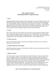
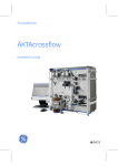
Kvick Lab™ Cassette Holder II
User Manual
Page intentionally left blank
Table of Contents
Table of Contents
1
Introduction ..........................................................................................................
5
1.1
1.2
1.3
About this manual ................................................................................................................................
Important user information .............................................................................................................
Regulatory information ......................................................................................................................
6
7
9
Safety instructions ...............................................................................................
10
2.1
2.2
Safety precautions ...............................................................................................................................
Recycling information .........................................................................................................................
11
14
3
Kvick Lab Cassette Holder II overview .............................................................
15
4
Unpacking ..............................................................................................................
19
5
Installation ............................................................................................................
21
5.1
5.2
Installation of Kvick Lab holder ll ...................................................................................................
Installation of cassettes .....................................................................................................................
22
24
6
Maintenance .........................................................................................................
34
7
Troubleshooting ...................................................................................................
37
8
Reference information ........................................................................................
39
8.1
8.2
Specifications .........................................................................................................................................
Chemical resistance ............................................................................................................................
40
42
Index .......................................................................................................................
43
2
Kvick Lab Cassette Holder ll User Manual 29-0271-61 AB
3
Page intentionally left blank
1 Introduction
1
Introduction
About this chapter
This chapter contains important user information, descriptions of safety notices, regulatory information, and intended use of Kvick Lab Cassette Holder II.
In this chapter
This chapter contains the following sections:
Section
See page
1.1 About this manual
6
1.2 Important user information
7
1.3 Regulatory information
9
Kvick Lab Cassette Holder ll User Manual 29-0271-61 AB
5
1 Introduction
1.1 About this manual
1.1
About this manual
Purpose of this document
The User Manual provides you with the instructions you need to use
Kvick Lab Cassette Holder II.
Scope of this document
This manual is valid for Kvick Lab Cassette Holder II. Detailed information regarding
cassettes or filtration systems is not covered.
More information
More information related to the use of Kvick Lab Cassette Holder II can be found in the
following documents:
6
•
ÄKTA flux 6 Operating Instructions, article number 29-0468-96
•
Cross flow filtration Method Handbook, article number 29-0850-76
•
Kvick Lab and Kvick Flow Cassettes User Manual, article number 18-1171-69
Kvick Lab Cassette Holder ll User Manual 29-0271-61 AB
1 Introduction
1.2 Important user information
1.2
Important user information
Read this before using
Kvick Lab Cassette Holder II
All users must read the entire User Manual before installing, using or maintaining
the cassette holder.
Always keep the User Manual at hand when using Kvick Lab Cassette Holder II.
Do not use Kvick Lab Cassette Holder II in any other way than described in the user
documentation. If you do, you may be exposed to hazards that can lead to personal injury,
you may cause damage to the equipment, and no warranty will apply.
Intended use of
Kvick Lab Cassette Holder II
The Kvick Lab Cassette Holder II is designed to be used with one to five filter cassettes
for cross flow membrane separations, with a cross flow rate of 600 to 800
ml/min/per 0.11 m2 cassette.
WARNING
Do not use Kvick Lab Cassette Holder II in any other way than described in Kvick Lab Cassette Holder ll user manual.
Prerequisites
In order to use Kvick Lab Cassette Holder II safely and according to the intended purpose,
the following prerequisites must be met:
•
You should be acquainted with the use of general bioprocessing equipment and with
handling of biological materials.
•
You must read and understand the Safety chapter of this User Manual.
•
The Kvick Lab Cassette Holder II must be installed according to the instructions in
Chapter 5 Installation, on page 21.
Kvick Lab Cassette Holder ll User Manual 29-0271-61 AB
7
1 Introduction
1.2 Important user information
Safety notices
This user documentation contains safety notices (WARNING, CAUTION, and NOTICE)
concerning the safe use of the product. See definitions below.
WARNING
WARNING indicates a hazardous situation which, if not avoided,
could result in death or serious injury. It is important not to proceed
until all stated conditions are met and clearly understood.
CAUTION
CAUTION indicates a hazardous situation which, if not avoided,
could result in minor or moderate injury. It is important not to proceed until all stated conditions are met and clearly understood.
NOTICE
NOTICE indicates instructions that must be followed to avoid
damage to the product or other equipment.
Notes and tips
8
Note:
A note is used to indicate information that is important for trouble-free and
optimal use of the product.
Tip:
A tip contains useful information that can improve or optimize your procedures.
Kvick Lab Cassette Holder ll User Manual 29-0271-61 AB
1 Introduction
1.3 Regulatory information
1.3
Regulatory information
Regulatory compliance
This product fulfils the following requirements:
Standard
Description
USP class VI, EN 10204 2.1
The tested materials have been tested for process wetted and pressure retaining polymers and elastomers.
CFR 177
The material is in compliance with Code of Federal
Regulations (CFR), Food and Drugs Title 21, Part 177 FDA.
AFO
Animal free origin, alt. EMEA/410/01 compliant
The polymeric material is in accordance with the conditions for tallow derivates in the CPMP Note for Guidance
(EMA/410/01 Rev. 3) and therefore BSE/TSE contamination is unlikely. Where an absolutely animal free claim
can not be made, a statement to confirm that a component is free from BSE/TSE infectious prions is not scientifically possible.
Kvick Lab Cassette Holder ll User Manual 29-0271-61 AB
9
2 Safety instructions
2
Safety instructions
About this chapter
This chapter describes safety precautions for Kvick Lab Cassette Holder II. Recycling is
also described.
Important
WARNING
Before installing, operating or maintaining
Kvick Lab Cassette Holder II, all users must read and understand
the entire contents of this chapter to become aware of the hazards involved.
Failure to do this may cause human injury or death, or damage to
the equipment.
In this chapter
This chapter contains the following sections:
Section
10
See page
2.1 Safety precautions
11
2.2 Recycling information
14
Kvick Lab Cassette Holder ll User Manual 29-0271-61 AB
2 Safety instructions
2.1 Safety precautions
2.1
Safety precautions
Introduction
The safety precautions in this section are grouped in the following categories:
•
General precautions, on page 11
•
Personal protection, on page 12
•
Installing and moving, on page 12
•
System operation, on page 12
•
Maintenance, on page 13
General precautions
WARNING
The customer must make sure installation, maintenance, operation
and inspection is carried out by qualified personnel who are adequately trained, understand and adhere to local regulations and
the user manual, and have a thorough knowledge of
Kvick Lab Cassette Holder II and the entire process.
WARNING
Do not operate the product in any other way than described in the
Kvick Lab Cassette Holder ll user manual.
CAUTION
If Kvick Lab Cassette Holder II leaks, it can release potentially hazardous process fluids, causing bodily harm. Make sure that the
pressure limit is set to the specified maximum pressure of the filter.
Periodically check parts for wear and make sure components are
assembled correctly.
Kvick Lab Cassette Holder ll User Manual 29-0271-61 AB
11
2 Safety instructions
2.1 Safety precautions
Personal protection
WARNING
Always use appropriate Personal Protective Equipment (PPE) during
installation and maintenance of Kvick Lab Cassette Holder II.
Installing and moving
WARNING
Before removing the Kvick Lab Cassette Holder II from the filtration
system, make sure that the flow path of the filter and the filter
holder is emptied and depressurized to an appropriate level for
safe handling.
CAUTION
Because of the weight of the Kvick Lab Cassette Holder II, great
care must be taken not to cause squeezing or crushing injuries
during movement. To prevent injury from dropping a cassette
holder on your feet or hands, make sure you have a secure, controlled grip, or the proper equipment to move the cassette holder.
Wear safety shoes.
System operation
WARNING
Before connecting the filter to Kvick Lab Cassette Holder II, read
the instructions for use of the filter. To avoid exposing the filter to
excessive pressure, make sure that the pressure limit is set to the
specified maximum pressure of the filter.
12
Kvick Lab Cassette Holder ll User Manual 29-0271-61 AB
2 Safety instructions
2.1 Safety precautions
Maintenance
WARNING
Before any maintenance or decommissioning work is performed
on Kvick Lab Cassette Holder II, make sure that the holder:
•
is empty and depressurized.
•
is disconnected from process feed.
Also make sure that all process wetted areas are clean and decontaminated.
Kvick Lab Cassette Holder ll User Manual 29-0271-61 AB
13
2 Safety instructions
2.2 Recycling information
2.2
Recycling information
Introduction
This section contains information about the decommissioning of
Kvick Lab Cassette Holder II.
Decontamination
Kvick Lab Cassette Holder II shall be decontaminated before decommissioning and all
local regulations shall be followed with regard to scrapping of the equipment.
Disposal, general instructions
When taking Kvick Lab Cassette Holder II out of service, the different materials must be
separated and recycled according to national and local environmental regulations.
14
Kvick Lab Cassette Holder ll User Manual 29-0271-61 AB
3 Kvick Lab Cassette Holder II overview
3
Kvick Lab Cassette Holder II
overview
About this chapter
This chapter provides an overview of Kvick Lab Cassette Holder II parts.
Kvick Lab Cassette Holder ll User Manual 29-0271-61 AB
15
3 Kvick Lab Cassette Holder II overview
Kvick Lab Cassette Holder II
illustration
6
7
8
9 10 11
5
12
4
13
3
2
1
16
Kvick Lab Cassette Holder ll User Manual 29-0271-61 AB
3 Kvick Lab Cassette Holder II overview
Part
Function
1
Stand
2
Permeate (drainage) port
3
Feed port
4
Flow distribution manifold
5
Retentate port
6
Permeate port
7
Spacer 100 mm
8
Spacer 50 mm
9
Spacer 25 mm
10
Nut and washer
11
Tie rod
12
Guide rod
13
Back plate
Cassettes and spacers
Spacers with three different lengths, 25, 50 and 100 mm are supplied with the holder.
The spacers enable that up to five Kvick Lab cassettes can be installed in the holder.
Kvick Lab Cassette Holder ll User Manual 29-0271-61 AB
17
3 Kvick Lab Cassette Holder II overview
Guide rods
Two guide rods, with the diameters 9 and 6 mm, are delivered with the holder. The 9
mm guide rod is suitable for Kvick Lab cassettes, and the other may be suitable for other
brands.
18
Kvick Lab Cassette Holder ll User Manual 29-0271-61 AB
4 Unpacking
4
Unpacking
About this chapter
This chapter describes the contents of the delivery package and how to unpack the
Kvick Lab Cassette Holder II.
Safety precautions
CAUTION
Because of the weight of the Kvick Lab Cassette Holder II, great
care must be taken not to cause squeezing or crushing injuries
during movement. To prevent injury from dropping a cassette
holder on your feet or hands, make sure you have a secure, controlled grip, or the proper equipment to move the cassette holder.
Wear safety shoes.
Package contents
Each shipment of a Kvick Lab Cassette Holder II includes the following components:
•
Kvick Lab Cassette Holder II
•
Cleaning-In-Place (CIP) cassette
•
two gaskets for filter cassettes
•
torque wrench and socket
•
four TC gaskets
•
four TC clamps
•
stopper plug
•
user manual
Kvick Lab Cassette Holder ll User Manual 29-0271-61 AB
19
4 Unpacking
Visual inspection
Check:
•
that all equipment is enclosed in the box according to the packing list.
•
the equipment for any apparent damage and document carefully, if found.
If any equipment is missing or damage is found, contact your GE representative immediately.
Unpacking the
Kvick Lab Cassette Holder II
Follow the general unpacking instructions below to unpack the filter holder.
20
Step
Action
1
Place the box on the floor.
2
Open the top of the box and remove the foam insert.
3
Remove the accessories and the user manual.
4
Lift Kvick Lab Cassette Holder II and place it on a laboratory bench.
Kvick Lab Cassette Holder ll User Manual 29-0271-61 AB
5 Installation
5
Installation
About this chapter
This chapter describes how to install the Kvick Lab Cassette Holder II.
In this chapter
This chapter contains the following sections:
Section
See page
5.1 Installation of Kvick Lab holder ll
22
5.2 Installation of cassettes
24
Kvick Lab Cassette Holder ll User Manual 29-0271-61 AB
21
5 Installation
5.1 Installation of Kvick Lab holder ll
5.1
Installation of Kvick Lab holder ll
Where to install the holder
The integration of the cassette holder into your cross-flow system depends upon your
application and filtration goals. The image below shows a basic example cross-flow
configuration. To learn about alternate system configurations for special applications,
contact your GE representative.
Pressure
sensor
Diafiltration
solution
Retentate line
Permeate
control
valve
Collection
vessel
Permeate line
Feed
reservoir
Pressure
sensor
Kvick Lab
Cassette Holder ll
Pump
Feed line
Drain
line
Drain
valve
Installation
Follow these steps to install the Kvick Lab Cassette Holder II in the cross-flow system:
Note:
22
Keep tubing short to minimize holdup volume.
Kvick Lab Cassette Holder ll User Manual 29-0271-61 AB
5 Installation
5.1 Installation of Kvick Lab holder ll
3
2
1
4
Step
Action
1
Place Kvick Lab Cassette Holder II next to your cross-flow system.
2
Connect the holder's feed port (1), to the feed line tubing using a TC gasket
and a TC clamp.
3
Connect the holder's retentate port (2), to the retentate line tubing using a
TC gasket and a TC clamp.
4
Connect the holder's upper permeate port (3), to the permeate line tubing
using a TC gasket and a TC clamp.
5
Attach the stopper plug to the holder's lower permeate port (4). The port can
be used for drainage, in such case connect a valve to the lower port.
Kvick Lab Cassette Holder ll User Manual 29-0271-61 AB
23
5 Installation
5.2 Installation of cassettes
5.2
Installation of cassettes
Safety precautions
WARNING
Before connecting the filter to Kvick Lab Cassette Holder II, read
the instructions for use of the filter. To avoid exposing the filter to
excessive pressure, make sure that the pressure limit is set to the
specified maximum pressure of the filter.
Cassette types
Kvick Lab Cassette Holder II can hold multiple cassettes depending upon the cassette
type and the membrane area the application requires. The table below describes the
available cassette types and the torque required to install the cassettes in the holder.
Note:
The cassette holder follow industry standard cassette dimensions and accepts
other cassettes of standard layout.
Cassette types
Cassette size
Number of
Nut torque
cassettes
Kvick Lab
0.11 m² (1.2 ft²)
1 to 5
20.3 Nm (180 lb-in)
Prepare the cassette(s)
Unpack and prepare the cassette(s) for use according to the manufacturer's instructions.
24
Kvick Lab Cassette Holder ll User Manual 29-0271-61 AB
5 Installation
5.2 Installation of cassettes
Prepare the holder
Follow these steps to prepare the holder for insertion of the cassettes.
Step
Action
1
Remove the nuts and washers.
2
Remove the spacers.
Kvick Lab Cassette Holder ll User Manual 29-0271-61 AB
25
5 Installation
5.2 Installation of cassettes
Step
Action
3
Slide the back plate away from the flow distribution manifold.
Insert the cassette(s)
Follow these steps to insert the cassette(s) into the holder.
Step
Action
1
Check that a guide rod of the correct size is used. If not, change the guide
rod to a fitting size.
Note:
To loosen the guide rod, turn it anti-clockwise. To fasten the guide rod, turn
it clockwise.
2
26
Clean and wet a gasket by rinsing it with distilled (DI) water, or water-forinjection (WFI).
Kvick Lab Cassette Holder ll User Manual 29-0271-61 AB
5 Installation
5.2 Installation of cassettes
Step
Action
3
Place the filter gasket against the back plate, aligning the holes in the gasket
with the holes in the back plate.
Result: The gasket will stick to the manifold.
Note:
If a cassette is used without built-in gaskets; gaskets need to be placed at the
distribution plate and between the cassettes.
Kvick Lab Cassette Holder ll User Manual 29-0271-61 AB
27
5 Installation
5.2 Installation of cassettes
Step
Action
4
Place the cassette into the holder with the gasket-side of the cassette facing
the flow distribution manifold, and slide the cassette against the flow distribution manifold.
Repeat this step, to install two or more cassettes.
28
Kvick Lab Cassette Holder ll User Manual 29-0271-61 AB
5 Installation
5.2 Installation of cassettes
Step
Action
5
Slide the back plate forward to hold the cassettes in place. Make sure that
the holes in the manifold, gasket, and cassettes line up.
6
Add spacers to the tie rods until about 16 mm (0.75-inches) of the threads
are exposed on each tie rod.
7
Reinstall the washers and nuts. Tighten the nuts by hand.
Kvick Lab Cassette Holder ll User Manual 29-0271-61 AB
29
5 Installation
5.2 Installation of cassettes
Step
Action
8
Using the supplied torque wrench and socket, tighten each nut alternately,
1/4 turn at a time, until each nut has been tighten to a torque of 20.3 Nm
for Kvick Lab cassettes.
Note:
The torque value is depending on the cassette type used.
Final considerations before use
Once the cassettes are installed in the holder, the following actions should be taken:
•
test the filtration system for possible leakage according to the filtration system's
operating instructions
•
test the water flux and the integrity of the cassettes according to the cassette's user
manuals, for example Kvick Lab and Kvick Flow Cassettes User Manual, article no.
18-1171-69.
•
make sure that the pressure limits for installed filters are not exceeded
Remove the cassette(s)
WARNING
Before removing the Kvick Lab Cassette Holder II from the filtration
system, make sure that the flow path of the filter and the filter
holder is emptied and depressurized to an appropriate level for
safe handling.
Follow these steps to remove the cassette(s) in the Kvick Lab Cassette Holder II:
30
Kvick Lab Cassette Holder ll User Manual 29-0271-61 AB
5 Installation
5.2 Installation of cassettes
Step
Action
1
Remove the nuts and washers.
2
Remove the spacers.
Kvick Lab Cassette Holder ll User Manual 29-0271-61 AB
31
5 Installation
5.2 Installation of cassettes
32
Step
Action
3
Slide the back plate away from the flow distribution manifold.
4
Remove the cassette(s) and the gasket from the holder.
Kvick Lab Cassette Holder ll User Manual 29-0271-61 AB
5 Installation
5.2 Installation of cassettes
Step
Action
5
Clean the Kvick Lab Cassette Holder II according to the instructions in Clean
the permeate line and the holder, on page 35.
Kvick Lab Cassette Holder ll User Manual 29-0271-61 AB
33
6 Maintenance
6
Maintenance
About this chapter
This chapter provides required information to enable users and service personnel to
clean and maintain the Kvick Lab Cassette Holder II.
Safety precautions
WARNING
Before any maintenance or decommissioning work is performed
on Kvick Lab Cassette Holder II, make sure that the holder:
•
is empty and depressurized.
•
is disconnected from process feed.
Also make sure that all process wetted areas are clean and decontaminated.
CAUTION
If Kvick Lab Cassette Holder II leaks, it can release potentially hazardous process fluids, causing bodily harm. Make sure that the
pressure limit is set to the specified maximum pressure of the filter.
Periodically check parts for wear and make sure components are
assembled correctly.
Inspection
Make the inspections in the list below periodically, depending on normal or frequent use
of Kvick Lab Cassette Holder II. The system owner is solely responsible for establishing
applicable routines for periodic maintenance.
Make these inspections:
34
•
Inspect the tie rods and nuts for excessive wear and replace as needed.
•
Inspect the mating surfaces of the flow manifold and backing plate for scratches.
Kvick Lab Cassette Holder ll User Manual 29-0271-61 AB
6 Maintenance
•
Inspect the TC clamps and TC gaskets for damage or wear, and replace as needed.
•
Check the rigidity of the stand. If the stand wobbles, check that the plastic supports
are not damaged and the screws are tightened.
If the mating surfaces of the flow manifold and backing plate become excessively
scratched, contact your GE representative for assistance.
CIP
Step
Action
1
Place the CIP cassette gasket on the flow distribution manifold.
2
Insert the CIP cassette in the cassette holder the same way as cassettes are
inserted in the Kvick Lab Cassette Holder II, refer to Insert the cassette(s), on
page 26.
3
Clean the system with the CIP cassette installed in the
Kvick Lab Cassette Holder II.
4
After CIP, remove the CIP cassette holder the same way as cassettes are
removed, refer to Remove the cassette(s), on page 30.
5
Remove the CIP cassette gasket.
Clean the permeate line and the
holder
Follow the instructions below to clean the permeate line and the holder after use and
after CIP.
Step
Action
1
Wash the permeate line with clean water to remove dirt and residual process/cleaning solutions.
2
Wash down the exterior components of Kvick Lab Cassette Holder II with
clean water and blow the wash water out of the flow manifold channels
with compressed air.
3
Wipe the holder dry with a clean, lint-free cloth.
Kvick Lab Cassette Holder ll User Manual 29-0271-61 AB
35
6 Maintenance
Storage of
Kvick Lab Cassette Holder II
To store the Kvick Lab Cassette Holder II, clean it and place several layers of a clean
cloth between the flow manifold and the backing plate. Install the spacers, washers, and
nuts, and lightly hand tighten to hold the cloth and backing plate in place. Place the
holder in a dry, protected area such as a cabinet to prevent contamination or accidental
dropping.
NOTICE
Do not store filter cassettes in Kvick Lab Cassette Holder II.
36
Kvick Lab Cassette Holder ll User Manual 29-0271-61 AB
7 Troubleshooting
7
Troubleshooting
About this chapter
This chapter provides information required to enable users to identify and correct
problems that may occur when using the Kvick Lab Cassette Holder II.
If the suggested actions in this guide do not solve the problem, or if the problem is not
covered by this guide, contact your GE representative for advice.
Troubleshooting guide
The table below describes problems that may occur with Kvick Lab Cassette Holder II,
together with possible corrective actions.
Symptom
Possible Cause
Corrective action
Holder leaks from between flow
manifold and backing plate
Insufficient clamping force
Check tie rod nut torque
System is being run at excessive
operating pressures
Run system at proper operating
pressures
Cassette gasket damaged or not
seated properly
Remove and inspect gasket. Reinstall gasket.
Cassette sealing surfaces damaged
Remove and inspect sealing
surfaces on the cassette. Replace cassette if necessary.
Sealing surface of the flow
manifold or backing plate
scratched
Inspect sealing surface of flow
manifold and backing plate for
scratches.
TC clamp connection gasket
missing, worn, damaged, improperly mounted, or wrong size
Inspect gasket for wear, damage, and proper sizing. Reinstall
gasket.
TC clamp loose
Tighten TC clamp
Process solution leaks from sanitary connections
Kvick Lab Cassette Holder ll User Manual 29-0271-61 AB
37
7 Troubleshooting
Symptom
Possible Cause
Corrective action
Feed pressure is too high
Cassette fouled
Clean cassette
Obstruction in feed line or retentate line
Inspect lines for obstruction
Feed inlet in cassette plugged
Switch feed and retentate lines
to reverse flow, and flush with
DI water or WFI. Retorque tie rod
nuts
Insufficient clamping force
Locate leaking area by feeling
air leak with hand, or by applying soapy water and looking for
bubbles. Remove, inspect, and
reinstall cassette and gasket
Kvick Lab Cassette Holder II
leaks during integrity testing
38
Improperly seated cassette or
gasket
Sealing surface of holder or cassette damaged
Locate leaking area by feeling
air leak with hand, or by applying soapy water and looking for
bubbles. Remove cassette and
gasket and inspect sealing surface of flow manifold, backing
plate, and cassette
Faulty valve
Check integrity of valves and replace as needed.
Kvick Lab Cassette Holder ll User Manual 29-0271-61 AB
8 Reference information
8
Reference information
About this chapter
This chapter provides reference information that may become useful when installing,
operating, maintaining and troubleshooting Kvick Lab Cassette Holder II.
Kvick Lab Cassette Holder ll User Manual 29-0271-61 AB
39
8 Reference information
8.1 Specifications
8.1
Specifications
Dimensions
437
All dimensions are presented in mm.
259
267
Property
Value
Width
259 mm
Deep
267 mm
Height
437 mm
Mechanical data
40
Property
Value
Weight
7.7 kg
Feed, retentate, and permeate part fittings
1/2" TC
Kvick Lab Cassette Holder ll User Manual 29-0271-61 AB
8 Reference information
8.1 Specifications
Property
Value
Materials of construction
Stainless steel: flow distribution manifold,
back plate, tie rods, guide rods, washers,
and stand
Bronze: tie rod nuts
Type and number of cassettes
Kvick Lab – 0.11 m2 (maximum of 5 cassettes installed)
Property
Value
Cross-flow rate
600 to 800 ml/min/per 0.11 m2 cassette
Recommended operating temperature
-5 to 50°C
Maximum operating temperature
121°C
Maximum operating pressure
4 bar (g)
Operating pH
1 to 14
Cassette holdup volume
20 ml
Hardware holdup volume (feed/retentate)
< 2 ml
Maximum membrane area
0.55 m2
Capacity
Kvick Lab Cassette Holder ll User Manual 29-0271-61 AB
41
8 Reference information
8.2 Chemical resistance
8.2
Chemical resistance
The table below gives chemicals that may be used with the Kvick Lab Cassette Holder II.
Consult Kvick Lab and Kvick Flow Cassettes User Manual, article no. 18-1171-69 for
guidelines on the chemical compatibility of cassettes.
Chemical
Concentration
Max time / cycle
Max acc. expos.
Usage
Acetic acid
25%
3h
3000 h
CIP
Acetone
10%
1h
N/A
UV cell test
Citric acid
pH 2 to 2.5
1 h at temp ≤ 60°C
1000 h
CIP
Ethanol
20%
12 months
N/A
Storage
Ethanol / Acetic
acid
20%
3h
3000 h
CIP
Guanidine hydrochloride
6M
5h
5000 h
CIP
Hydrochloric
acid
0.1 M at pH=1
1h
1000 h
CIP
Phosphoric acid
5%
Overnight
Unlimited
For SS passivation
2-propanol
30%
1h
1000 h
CIP
Sodium chloride
0 to 3 M
3h
3000 h
Purification, CIP
Sodium hydroxide
1 M at pH=14
0.5 M
0.01 M at pH=12
24 h at temp ≤40°C
3 h at temp ≤ 60°C
12 months
1000 days
3000 h
Unlimited
CIP
CIP
Storage
Sodium
hypochlorite
300 ppm
3 h at temp ≤ 60°C
3000 h
CIP
Sodium hydroxide/Ethanol
1 M or 20%
3h
3000 h
CIP
Urea
8M
5h
5000 h
Purification, CIP
Cleaning solutions
1% to 6% Steris
CIP 100™, 0.5%
Henkel P3™-11, 0.2%
Micro, 0.2%
Terg-a-zyme™, 0.1%
Tween™ 80
3 h at temp ≤ 60°C
3000 h
CIP
42
Kvick Lab Cassette Holder ll User Manual 29-0271-61 AB
Index
Index
B
Back plate
insert, 29
remove, 32
Manifold, 17
inspect, 34
Membrane area, 41
N
C
Notes and tips, 8
Cassette, 36
clean, 38
insert, 26
inspect gasket, 37
prepare, 24
remove, 30
Chemical resistance, 42
CIP cassette, 19, 35
Clean
exterior, 35
Cross-flow rate, 41
O
D
Decontamination, 14
Dimensions, 40
Disposal, 14
F
Feed port, 17, 23
Filter gasket, 27
Flow distribution manifold, 17
G
Guide rod, 17–18
H
Holder
prepare, 25
Holdup volume, 41
I
Installation, 21–22
cassettes, 24
holder, 22
Intended use, 7
International standards, 9
M
Maintenance, 34
Kvick Lab Cassette Holder ll User Manual 29-0271-61 AB
Operating pressure, 41
Operating temperature, 41
P
Packing list, 19
Permeate drain port, 17
Permeate line
wash, 35
Permeate port, 17, 23
Prerequisites, 7
R
Retentate port, 17, 23
S
Safety
notices, 8
Safety precautions, 11
Spacer, 17
add, 29
remove, 25, 31
Stopper plug, 19, 23
Storage, 36
T
Technical overview, 15
Test
filtration system, 30
water flux, 30
Tie rod, 17
check, 37
inspect, 34
Torque wrench, 19
Trobleshooting guide, 37
U
Unpacking, 19–20
43
Index
visual inspection, 20
User information
important, 7
44
W
Weight, 40
Kvick Lab Cassette Holder ll User Manual 29-0271-61 AB
Page intentionally left blank
Page intentionally left blank
Page intentionally left blank
For local office contact information, visit
www.gelifesciences.com/contact
GE Healthcare Bio-Sciences AB
Björkgatan 30
751 84 Uppsala
Sweden
www.gelifesciences.com/filtration
GE and GE monogram are trademarks of General Electric Company.
Kvick Lab is a trademark of GE Healthcare companies.
© 2014 General Electric Company – All rights reserved.
First published May. 2014.
All goods and services are sold subject to the terms and conditions of sale of
the company within GE Healthcare which supplies them. A copy of these terms
and conditions is available on request. Contact your local GE Healthcare representative for the most current information.
GE Healthcare Europe GmbH
Munzinger Strasse 5, D-79111 Freiburg, Germany
GE Healthcare UK Limited
Amersham Place, Little Chalfont, Buckinghamshire, HP7 9NA, UK
GE Healthcare Bio-Sciences Corp.
800 Centennial Avenue, P.O. Box 1327, Piscataway, NJ 08855-1327, USA
GE Healthcare Japan Corporation
Sanken Bldg. 3-25-1, Hyakunincho Shinjuku-ku, Tokyo 169-0073, Japan
29-0271-61 AB 05/2014 a1716