1
EE 400L
Analog
University of Nevada Las Vegas
Linear
Modulations
Experiment#1
Department of Electrical and Computer Engineering
2- AM GENERATION
Low frequency term a(t)
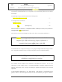
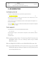
To generate a voltage defined by eqn. (8) you need first to generate the term a(t).
( )
( )
… 25
Note that this is the addition of two parts, a DC term and an AC term. Each part may be of any
convenient amplitude at the input to an ADDER.
The DC term comes from the VARIABLE DC module, and will be adjusted to the amplitude ‘A’ at
the output of the ADDER.
The AC term
( ) will come from an AUDIO OSCILLATOR, and will be adjusted to the amplitude
‘A.m’ at the output of the ADDER.
Carrier supply c(t)
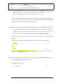
The 100 kHz carrier c(t) comes from the MASTER SIGNALS module.
( )
(
)
… 26
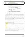
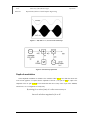
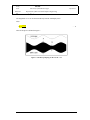
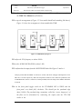
The block diagram of Figure 6, which models the AM equation, is shown modelled by TIMS in
Figure 15 below.
To build the model:
T23 first patch up according to Figure 15, but omit the input X and Y connections to the
MULTIPLIER. Connect to the two oscilloscope channels using the SCOPE
SELECTOR, as shown.
T24 use the FREQUENCY COUNTER to set the AUDIO OSCILLATOR to about 1 kHz.
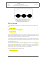
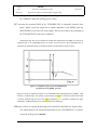
T25 switch the SCOPE SELECTOR to CH1-B, and look at the message from the AUDIO
OSCILLATOR. Adjust the oscilloscope to display two or three periods of the sine
wave in the top half of the screen.
2
3