1
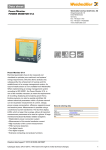
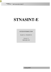
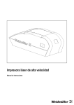
WAVE TTA
User Manual
Foreword
Foreword
Revision history
Version
Date
Change
0.0
04/08
First edition
Contact address
Weidmüller Interface GmbH & Co. KG
Postfach 3030
32720 Detmold
Klingenbergstraße 16
32758 Detmold
Germany
Phone +49 (0) 5231 14-0
Fax +49 (0) 5231 14-2083
E-Mail [email protected]
Internet www.weidmueller.com
5662300000/00/04.08
3
Contents
Contents
Foreword ............................................................................................................................3
Revision history................................................................................................................................................3
Contact address................................................................................................................................................3
Contents .............................................................................................................................4
1.
Approvals...............................................................................................................7
1.1
CE........................................................................................................................................................8
1.2
UL........................................................................................................................................................8
1.3
GL........................................................................................................................................................8
2.
Warrantee statement.............................................................................................9
2.1
36 months warranty ........................................................................................................................10
3.
Notes on Safety ...................................................................................................11
3.1
Electrical precautions .....................................................................................................................12
3.2
Handling ...........................................................................................................................................12
4.
Introduction .........................................................................................................13
4.1
Symbol identification ......................................................................................................................14
4.2
Types / article numbers ..................................................................................................................14
4.3
General description / applications / examples.............................................................................14
5.
Operation .............................................................................................................17
5.1
Status & alarm LEDs .......................................................................................................................18
5.2
Functional block diagram...............................................................................................................19
5.3
Specifications ..................................................................................................................................20
6.
Installation ...........................................................................................................23
6.1
General (Competence Warning) ....................................................................................................24
6.2
Mounting / Environmental / EMI protection / warm up ................................................................24
6.3
Marking.............................................................................................................................................25
6.4
Electrical Connections ...................................................................................................................25
6.5
Connection diagram........................................................................................................................26
4
5662300000/00/04.08
Contents
7.
Setup / Configuration..........................................................................................29
7.1
Default setting .................................................................................................................................30
7.2
CBX100USB introduction ...............................................................................................................30
7.3
Configuration / diagram wiring ......................................................................................................30
8.
TTA-Set software.................................................................................................31
8.1
Description.......................................................................................................................................32
8.2
Installation .......................................................................................................................................32
8.3
Starting/exiting TTA-Set .................................................................................................................32
8.4
Title bar ............................................................................................................................................32
8.5
Overview parameters ......................................................................................................................34
8.6
Run mode.........................................................................................................................................41
8.7
Product identification .....................................................................................................................41
8.8
Updates ............................................................................................................................................42
9.
Testing the product.............................................................................................43
9.1
Test procedure ................................................................................................................................44
10.
Troubleshooting..................................................................................................47
10.1
Troubleshooting ..............................................................................................................................48
Appendix ..........................................................................................................................49
Appendix A: Article Overview .......................................................................................................................50
Index
...........................................................................................................................................................51
5662300000/00/04.08
5
Contents
6
5662300000/00/04.08
Approvals
1.
Approvals
1.1
CE........................................................................................................................................................8
1.2
UL........................................................................................................................................................8
1.3
GL........................................................................................................................................................8
5662300000/00/04.08
7
Approvals
1.1
CE
CE Declaration is available from Weidmüller.
1.2
UL
Listing approval (cULus) is pending.
1.3
GL
Germanischen Lloyd approval is pending.
8
5662300000/00/04.08
Warrantee statement
2.
Warrantee statement
2.1
36 months warranty ........................................................................................................................10
5662300000/00/04.08
9
Warrantee statement
2.1
36 months warranty
Weidmüller gives a 36 months warranty on the
Wave TTA product in accordance with the warranty
terms as described in the general conditions of sale
of the Weidmüller company which has sold the
products to you.
Weidmüller warrants to you that such products the
defects of which have already existed at the time
when the risk passed will be repaired by Weidmüller
free of charge or that Weidmüller will provide a new,
functionally equivalent product to replace the defective one.
The warranty referred to above covers Weidmüller
products. Safe where expressively described otherwise in writing in this catalogue/product description,
Weidmüller gives no warranty or guarantee as to the
interoperability in specific systems or as to the fitness for any particular purpose. To the extent permitted by law, any claims for damages and reimbursement of expenses, based on whatever legal
reason, including contract or tort, shall be excluded.
Where not expressively stated otherwise in this warranty, the general conditions of purchase and the
expressive liability commitments therein of the respective Weidmüller company which has sold the
products to you shall be applicable
10
5662300000/00/04.08
Notes on Safety
3.
Notes on Safety
3.1
Electrical precautions .....................................................................................................................12
3.2
Handling ...........................................................................................................................................12
5662300000/00/04.08
11
Notes on Safety
3.1
Electrical precautions
DANGER!
This product may be connected to potentially lethal voltages!
WARNING!
• Before you remove or mount the unit,
turn-off the power supplies – i.e. to
the instrument and to the relays, if
used.
• Product electronics must not be removed from its enclosure without
disconnecting power sources.
• Follow ESD installation regulations,
including the EMI precautions given
in chapter 6.
3.2
Handling
Check on receipt that the product received corresponds to the one ordered.
Also check that a CD (which includes the User Manual and configuration software) has been supplied in
the carton.
Figure 1
Handling
Unpack the product carefully, and ensure the
CD/User Manual is kept with the product until it is
permanently mounted.
There are no procedures which involve the user removing the product electronics from its housing.
Set-up or Re-configuration (see chapter 7) is via a
connector located behind the front flap, which is released by small screwdriver (see Figure 1).
12
5662300000/00/04.08
Introduction
4.
Introduction
4.1
Symbol identification ......................................................................................................................14
4.2
Types / article numbers ..................................................................................................................14
4.3
General description / applications / examples.............................................................................14
5662300000/00/04.08
13
Introduction
4.1
Symbol identification
DANGER!
Potentially lethal voltages.
The CE mark proves the compliance of
the product with the requirements of the
directives.
4.3
General description / applications / examples
Wave TTA is an accurate and stable signal converter / isolator / alarm generator for use in measurement and control systems. In one model, a wide
variety of input / output range and type settings can
be configured, using a separate (CBX100 USB) interface and (TTA SET) software. The TTA can be
powered from DC or AC sources between 18 and
264 volts.
This User Manual covers the following product
types / article numbers
The primary characteristic of the Wave TTA is its
versatility of input / output configurability. Hence
many of the standard functions performed by DIN
rail mounted conditioners can be done by the TTA,
such as
WAS6 TTA
8939670000
• Conversion (current to voltage, and vice versa)
WAZ6 TTA
8939680000
• Isolation of temperature sensor and DC inputs
CBX100 USB
7940025031
• Linearization of temperature sensor inputs
4.2
Types / article numbers
The only difference between the products is the
connection type. The WAS6 TTA has screw connectors and the WAVZ6 TTA has tension clamp connectors.
• Transmission of sensor signals over long distance
• Characterising signals from DC transmitters
• Process alarm generation
• Relay control between high and low values
can be done by the TTA.
14
5662300000/00/04.08
Introduction
Typical Applications
Typical of applications for the TTA is the conversion
of thermocouple temperature input (low range of millivolts) into a high level (e.g. 4-20 mA) value for
transmission to a control system.
In this type of installation the TTA provides:
• Linearization of the standard thermocouple temperature/millivolts characteristic.
• Selectable output value for a thermocouple-break
event.
• Flashing LED status indicator on the unit front on
thermocouple-break.
• Relay alarm output if required on thermocouplebreak.
• Relay alarm output on high or low process temperature.
• Isolation of the input signal to the control system.
This allows the user to use a thermocouple with a
grounded hot junction for a quick response at the
measurement point. This would otherwise convey
electromagnetic influences (humming) into the
control system.
Figure 2
Installation overview
5662300000/00/04.08
15
Introduction
16
5662300000/00/04.08
Operation
5.
Operation
5.1
Status & alarm LEDs .......................................................................................................................18
5.2
Functional block diagram...............................................................................................................19
5.3
Specifications ..................................................................................................................................20
5662300000/00/04.08
17
Operation
5.1
Status & alarm LEDs
Status LED
Under normal conditions this (green) LED is on continuously.
Analogue Output status with alarm
• User may select output value under fault conditions
• Output compliant with NAMUR recommendations
(NE43) can be set (<3.6 mA or >21 mA)
Input fault detection
Input faults such as short circuit or open circuit can
be detected for most input types. These are shown
in the table below.
Input type
A
B
C
Figure 3
LEDs
A Status LED
Thermocouple
Yes
Yes
RTD
Yes
Yes
Millivolts
Yes
No
Volts (Positive)
Yes
No
Milliamps
(Passive)
Yes*
No
Milliamps (Active)
Yes
Yes
Resistance
Yes
Yes
Potentiometer
Yes
Yes**
Table 2
B ALARM 2
*
C ALARM 1
Detection
Open circuit Short circuit
Input fault detection
Open circuit not detected for live zero ranges
** Short circuit for end-to-end
The following table shows how alarm conditions are
displayed.
Status indicator
Alarm conditions
Normal status
continuously on
Input open circuit
flashes at 0.5 Hz
Input short circuit
flashes at 5 Hz
Cold Junction error
2 pulses, rests, 2 pulses
Flash memory error
3 pulses, rests, 3 pulses
Table 1
18
Status indicators
5662300000/00/04.08
Operation
5.2
Figure 4
Functional block diagram
Functional block diagram
5662300000/00/04.08
19
Operation
5.3
Specifications
Input types
Thermocouple
Range -200...+1820 °C
Types B, E, J, K , L, N, R, S, T to IEC 60584 plus custom specific
RTD
2, 3, 4 wire, within the range -200...+850 °C, for Pt100, Pt1000 to
IEC 60571 and for Ni100 / Ni1000 to DIN 43760, for Cu10 and,100 plus
custom specific
Potentiometer
10 Ω...100 kΩ
Resistance
10 Ω...5 kΩ
Frequency
2 Hz...100 kHz
Voltage
within the range -200...600 mV (min span 4 mV),
within the range -20...50 V DC (min span 0.5 V)
Current
within the range -20...50 mA (min span 1 mA)
Current Loop supply
+24 V DC
Sensor break output
Selectable between -2% and 102% output
Analogue Output
DC voltage
0...5, 1...5, 0...10, 2...10 V or span-settable between -10...10 V
(min span 2.5 V)
DC current
0...20, 4...20, 0...10 mA, or span-settable between 0...20 mA
(min span 5 mA)
Max load (current / voltage)
700 Ω / >10 kΩ (>20 kΩ for -10 V…+10 V)
Action
Direct or Reverse Acting
Digital Output
Relays
2 x SPCO
Max voltage
250 V AC
Max current
3A
General Data
Supply voltage
18...264 V AC/DC
Rated power
< 3,5 W
Ambient operating range
-40...+70 °C
Isolation test
2.5 kV / 1 min
Rated voltage
300 V
20
5662300000/00/04.08
Operation
Performance
Accuracy
DC, RTD inputs <0.1% span.
Thermocouple inputs: 0.2% span (or 1 °C) + CJ error
Ambient temp effects
DC & RTD inputs < 0.01%/K
Thermocouple inputs < 0.01% of full scale/K + CJ error 0.07 °C/K
Step Response/
Cut-off Frequency
Settable within 60 ms -1880 ms / 1 Hz (3 dB)
Physical
Dimensions
92.4 x 112.5 x 45 mm
No. of connections
12
Connection types
screw or tension clamp
Housing material
UL 94 V0
Housing colour
Black
Ingress protection
IP20
Approvals
CE, cULus*, C1D2*, Zone 2 ATEX*, NEPSI* (*=pending)
Type
Order No.
WAS6 TTA
8939670000 (screw connectors)
WAZ6 TTA
8939680000 (tension clamp connectors)
Table 3
Specifications
5662300000/00/04.08
21
Operation
22
5662300000/00/04.08
Installation
6.
Installation
6.1
General (Competence Warning) ....................................................................................................24
6.2
Mounting / Environmental / EMI protection / warm up ................................................................24
6.3
Marking.............................................................................................................................................25
6.4
Electrical Connections ...................................................................................................................25
6.5
Connection diagram........................................................................................................................26
5662300000/00/04.08
23
Installation
6.1
General (Competence Warning)
Wave TTA instruments should only be installed by
technically qualified personnel with sufficient qualification or knowledge in the subject of instrumentation
and control engineering. Qualified personnel are defined as persons considered in 0105 Part 1 / DIN
EN 50110-1 as electrically skilled workers or electronically instructed personnel, or similar local standards.
6.2
Mounting / Environmental /
EMI protection / warm up
Mounting
Wave TTA is designed to be mounted onto a TS35
DIN rail.
It clips onto the rail via a spring-loaded mounting
foot, and can be removed via a spring release on the
edge of the product near the mounting rail.
Environment
Wave TTA is designed for use either indoors (IP20)
in a control panel, or in a weather-proof field enclosure. Its atmosphere should be dry, well ventilated
and dust-free.
Avoid mounting in locations subject to vibration or
physical impact.
EMI protection
Do not install input, output and power supply cables
close to sources of electrical interference. For example, such sources could include relays, contactors, motors and their controls, including thyristor
drives, and the cables which connect these devices.
Avoid installing TTA cables in the same ducting as
such cables.
Local electrical installation practices should be followed.
Warm-up
The product is designed to function as soon as
power is supplied. However a warm-up period of 15
minutes is required before it performs to the specifications above.
NOTE
When auxiliary power is switched on, for
the first 200 ms the TTA will consume
up to 200 mA.
Figure 5
24
Mounting on DIN rail
5662300000/00/04.08
Installation
6.3
Marking
Two markers are located below the top sets of terminals for costumer identification.
6.4
Electrical Connections
Input, output and power supply wiring is made via
numbered, pluggable connectors, which may be
screw clamp or tension clamp type, depending on
the item article number.
The connectors are coded to prevent the power
supply connector being fitted in the wrong position.
A
Test terminals are included to permit input and output currents to be monitored without disconnection
of cables (see connection diagram below).
NOTE
Ensure that the connectors are inserted
into the correct position (see connection diagram).
Figure 6
Module marker
A Markers
Article number:
1609880000 WS 15/5 MC NEUTRAL PU 480
5662300000/00/04.08
25
Installation
6.5
Connection diagram
The connection diagram below is printed on the side of the TTA housing.
Connection diagram – Power supply
Term. No.
24
0V
26
18 - 264 V DC / AC
Table 4
Power supply
Connection diagram – Input
Term.
No.
11
IPassive
<50 mA
IActive
<20 mA
In-
Resistor / RTD
V
<50 V
TC / V
<600 mV
2-Wire
3-Wire
4-Wire
In-
In-
R-
R-
12
In+
13
R+
14
Poti
Freq
R-
Start
In-
Sense-
Sense-
End
R+
R+
Wiper
+24 V
15
In+ /
TP+
IReturn /
TP+
16
TP-
TP-
21
In+
In+
(<50 V)
22
In+
(<30 V)
23
Table 5
26
Sense+
Input
5662300000/00/04.08
Installation
Connection diagram – Analogue output
Term. No.
0…20 mA
31
TP+
32
Out+ / TP-
33
Out-
0…10 V
41
Out-
42
Out+
43
Out-
Table 6
-10 V…+10 V
Out+
Analogue output
Connection diagram – Digital output
Term. No.
Alarm 1
34
N/C
35
N/O
36
COM
Alarm 2
44
N/C
45
N/O
46
COM
Table 7
Digital output
5662300000/00/04.08
27
Installation
28
5662300000/00/04.08
Setup / Configuration
7.
Setup / Configuration
7.1
Default setting .................................................................................................................................30
7.2
CBX100USB introduction ...............................................................................................................30
7.3
Configuration / diagram wiring ......................................................................................................30
5662300000/00/04.08
29
Setup / Configuration
7.1
Default setting
Input range
4-20 mA
ADS Speed
medium
Transfer function
Linear
Response time
0.25 s
Output range
4-20 mA
Action
direct
Low limit
0 mA
High Limit
20 mA
Output @ error
21.5 mA
Digital outputs 1 and 2
Disabled
Table 8
7.3
Figure 7
30
7.2
CBX100USB introduction
The CBX100USB is the configuration interface for
the wave TTA. This is the same interface as can be
used for configuring the ITX Plus universal transmitter.
Connection to the computer is via USB port, and to
the Wave TTA via a jack connector. Tx and Rx
status are indicated by LEDs on the CBX100.
Default settings
Configuration / diagram wiring
Configuration / diagram wiring
5662300000/00/04.08
TTA-Set software
8.
TTA-Set software
8.1
Description.......................................................................................................................................32
8.2
Installation .......................................................................................................................................32
8.3
Starting/exiting TTA-Set .................................................................................................................32
8.4
Title bar ............................................................................................................................................32
8.5
Overview parameters ......................................................................................................................34
8.6
Run mode.........................................................................................................................................41
8.7
Product identification .....................................................................................................................41
8.8
Updates ............................................................................................................................................42
5662300000/00/04.08
31
TTA-Set software
8.1
Description
8.3
Starting/exiting TTA-Set
The Windows based TTA-Set software is configuration software to set up the universal analogue conditioning module WAVE TTA via the interface
CBX100 USB.
Starting TTA-Set
1
Double-click on the icon
desktop.
8.2
2
Click on the Windows Start button, then select:
Programs > Weidmueller > TTA-Set.
Installation
You can start TTA-Set in two different ways:
on your computer
System Requirements
• Operation system Windows 2000 (SP4+), Windows XP, Windows Vista
• IBM PC with a spare USB port
• Weidmüller CBX100 USB interface
Installation note
Exiting TTA-Set
You can exit TTA-Set in the following ways.
1
Click the Exit button.
2
Click the X on the window frame.
8.4
Title bar
File
NOTE
New
Change the setting to default settings.
In order to install the program you need
administrator rights on the computer involved.
Open
Open a configuration file *.tta from the
hard disk.
Save
Save the actually configuration to a file
*.tta.
Installation of the CBX100 driver:
Print
Print the actually configuration.
With the file "CDM 2.04.06.exe" you can install the
USB drivers for the CBX 100 interface.
Exit
Exit the software TTA Set.
Figure 8
Title bar - File
Installing TTA-Set:
The TTA-Set software can be installed with the file
"setup.exe".
Getting Started
1
Open up Windows Explorer and select the “CDM
2.04.06” icon in the appropriate directory.
2
Double click on this icon and click OK to start the
installation process
3
Open up Windows Explorer and select the “Setup” icon in the appropriate directory.
4
Double click on this icon and click OK to start the
installation process.
5
Follow the step by step instructions on the
screen.
32
5662300000/00/04.08
TTA-Set software
Settings
Temperature unit
Set the unit of the temperature for the configuration. Celsius or Fahrenheit
Setpoint Unit
Set the unit of the digital output setpoint.
Percentage: of the input value
or the same unit of the input
signal.
Figure 9
Title bar - Settings
Info
About
Figure 10
Open an information window
about the software version
and the contact address of
Weidmüller.
Title bar - Info
5662300000/00/04.08
33
TTA-Set software
8.5
Overview parameters
Input parameters
Type of
input
Voltage - Range
V: -20 … +50 V DC
Min. Span 0.5 V
mV: -200 … +500 mV DC
Min. Span: 4 mV
Current - Range
Passive
Range mA: -20 … +50 mA
Min. Span: 1 mA
Active
Range mA: 0 … +20 mA
Min. Span: 1 mA
34
Type of Thermocouple
K: -200 … +1372 °C
J: -210 … +1200 °C
T: -200 … +400 °C
E: -200 … +1000 °C
N: -200 … +1300 °C
R: -50 … +1767 °C
S: -50 … +1767 °C
B: +50 … +1820 °C
L: -200 … +900 °C
U: -200 … +600 °C
User defined
RTD
RTD type:
Connection type:
PT100
PT1000
NI100
NI1000
NI120
Cu10 Ω at 25 °C
Cu100 Ω at 0 °C
User defined
2-wire
3-wire
4-wire
Resistor - Range
10 Ω… 5 kΩ
Potentiometer - Range
10-50 Ω
50-100 Ω
100-200 Ω
200-400 Ω
400-800 Ω
800-2 kΩ
2 k-6.5 kΩ
6.5 k-100 kΩ
Frequency - Sensitivity
Frequency range:
Min. Span:
Voltage range Pin21:
Voltage range Pin22:
2 Hz … 100 kHz
10 Hz
-50 V … +50 V DC
-30 V … +30 V DC
Pin
High noise
reduction
High Level
Low noise
reduction
Low Level
Max. voltage
range
22
550 mV
140 mV
±30 V
21
7.8 V
1.9 V
±50 V
5662300000/00/04.08
TTA-Set software
Transfer parameters
Transfer
function
Transfer function for the output signal:
Function
linear
SQRT
0,5
X^1.5
X^2
X^2.5
Out = In x
0.01
Out = In2,5 x
0.001
Output
in %
Output
in %
Output
in %
0
0
0
0
10
32
3
1
0.3
20
20
45
9
4
2
30
30
55
16
9
5
40
40
63
25
16
10
50
50
71
35
25
18
60
60
77
46
36
28
70
70
84
59
49
41
80
80
89
72
64
57
90
90
95
85
81
77
100
100
100
100
100
100
formula
Out = In
Out = In
x 10
Input
in %
Output
in %
Output
in %
0
0
10
Out = In
x 0.1
1,5
2
In the SQRT function has low flow cut off. If the input Is smaller than 1% the
out is zero.
Figure 11
5662300000/00/04.08
Transfer functions
35
TTA-Set software
Figure 12
User define transfer function
ADC Speed
Response
Time
Fast
Highest sampling rate
9.5 ms
Medium
50 - 60 Hz
60 ms
Slow
50 - 60 Hz
180 ms
Response time is the time between an input step and the output step.
ADC
speed
Fast
Medium
Slow
Response
time in ms
Voltage /
Current
mV /
Thermo
Potentiometer /
RTD
3-Wire
RTD
2-Wire
4-Wire
min.
140
60
90
60
max.
1000
1000
1000
1000
min.
250
170
350
180
max.
1070
1000
950
1050
min.
525
460
1020
470
max.
1350
1280
1880
900
Range response time
36
5662300000/00/04.08
TTA-Set software
Analogue output parameters
Type of
output
Voltage
Current
Voltage Max. Range:
-10.1 … +11 V DC
Min. Span: 2.5 V DC
Max. Range:
0 mA to 20 mA DC
Min. Span: 5 mA DC
Output – range
low
Lowest Value
This is the minimum voltage value
at the output (related to 0% input).
Lowest Value
This is the minimum current value
at the output (related to 0% input).
Output – range
high
Highest Value
This is the value at the output (related to 100% input).
Highest Value
This is the maximum current value
at the output (related to 100% input).
Direct or
reverse function
Direct action is output increasing
as input increases.
Reverse action is output decreasing as input increases.
Direct action is output increasing as
input increases.
Reverse action is output decreasing as input increases.
Output – low limit
Low Limit
This is the lowest possible value
at the output.
Low Limit
This is the lowest possible value at
the output.
Output – high limit
High Limit
This is the highest possible value
at the output.
High Limit
This is the highest possible value at
the output.
Output – for error
condition
Output @ Error
If an input or TTA error occurs the
output is set to this value.
Output @ Error
If an input or TTA error occurs the
output is set to this value.
5662300000/00/04.08
37
TTA-Set software
Digital output parameters
Alarm
Item
Operating
modes
Function
Disabled
The alarm is disabled.
Low Type
The alarm is switched on, if the input value is lower than the setpoint.
High Type
The alarm is switched on, if the input value is higher than the setpoint.
Window
The alarm is switched on, if the input value is outside the window value:
window range = setpoint ± window value
e.g.: setpoint 40%, window 10% = window value is from 30-50%.
Input Error
If an input or TTA error occurs the output is set to this value.
Alarm Relay
Normally energised
Normally de-energised
Settings
Table 9
38
No alarm
Alarm
Coil on
Coil off
No alarm
Alarm
Coil off
Coil on
Set Point
This is the relay switch on value 0…100%
Deadband
Switch off hysteresis in percent
e.g. high type, setpoint 50% and deadband 2%: the alarm switches on if
the value reaches 50% and switches off if the value decreases to 48%.
On Delay
Switch on delay in seconds
In 0.1 second steps
Off Delay
Switch off delay in seconds
In 0.1 second steps
Window
Set a range around the Setpoint in percent
Parameter
5662300000/00/04.08
TTA-Set software
High Alarm
Figure 13
Window Alarm
High Alarm
Figure 15
Window Alarm
Low Alarm
Figure 14
Low Alarm
5662300000/00/04.08
39
TTA-Set software
Alarm Time Delay
Figure 16
Alarm Time Delay
In this example the time delay is set for 20 seconds. At t1 the measurement exceeds the alarm value, but this
only lasts for 10 seconds so there is no trip. At t2 the measurement again exceeds the alarm trip value and
this lasts for longer than 20 seconds so the alarm trip occurs after 20 seconds.
40
5662300000/00/04.08
TTA-Set software
8.6
Run mode
Start communication with the TTA
1
Connect the WAVE TTA to a Power supply.
2
Connect the TTA with the CBX100 USB interface
to an USB port.
3
Start the software TTA-Set.
4
Input configuration
Select the input value.
5
Output configuration
Select the output value.
6
Alarm configuration
Set the alarm relay behaviour.
7
Send configuration to TTA
The button “Save to Instrument” transmits the
new configuration to the TTA.
8
Enter Password
Enter your password (the default password is
0000). To reset a personal password, send a request with the serial number of the Wave TTA to
the following e-mail address:
[email protected]
9
Read Values
With the button “Read Values” the actual values
of the TTA are displayed in the window “Running
values”.
If the button “Read Continuous” is activated the
values are updated every second (monitoring).
10 Read from Instrument
To check the current configuration in the connected TTA click on the “Read from instrument”
button.
• Alarm2: Shows the status of the second alarm relay
-
LED = red = relay switched on (alarm)
-
LED = off = relay switched off (no alarm)
8.7
Unit Type:
Description of the module
Serial No.:
The serial number is
printed on the side of the
module.
Firmware No.:
The firmware number of
the TTA device which is
connected.
Configured by:
The company name of the
person who last configured the module.
Initials:
Initials or the name of the
person who last configured the module.
Date:
The date when the module was last configured
the module.
ID Tag:
Typically, the user’s plant
reference
User Reference:
User descriptor
Version:
The Version of the software
Terminals:
Shows the terminal number where the sensor and
output signals are connected.
Running values
• Input: TTA input value in percent.
• Output: TTA output value in percent.
Product identification
Table 10
Product identification
• CJC Temperature: This the temperature in Centigrade or Fahrenheit at the cold junction point in
the WAVE TTA.
• Alarm1: Shows the status of the first alarm relay
-
LED = red = relay switched on (alarm)
-
LED = off = relay switched off (no alarm)
5662300000/00/04.08
41
TTA-Set software
A
Figure 17
Product identification
A Terminals
8.8
Updates
Downloading the latest version
The latest version of the TTA-Set Software is available from the Weidmüller website at
www.weidmueller.com.
42
5662300000/00/04.08
Testing the product
9.
Testing the product
9.1
Test procedure ................................................................................................................................44
5662300000/00/04.08
43
Testing the product
9.1
Test procedure
Following equipment is necessary to test the Wave TTA:
• Wave TTA Module: WAS 6 TTA (Order No. 893967) or WAZ 6 TTA (Order No. 893968)
• USB Interface unit CBX 100 USB (for configuration),
• Power supply - see chapter 5.3 - (e.g. 24 Vdc, such as model CP SNT 12 W (Order No. 991884 0024))
• Configuration Software TTA Set (for configuration)
• PC or Laptop, (for configuration)
• To test input to output transfer function an appropriate input signal source is needed, such as:
-
Calibrator Portacal 1000 (Order No. 7940010194) for DC current and Voltage input signals
-
Potentiometer e.g. 5 kΩ
-
Resistance box
-
Thermocouple source or “Millivolts source”
• Output meter (e.g. a dvm) to measure the range of voltage or current produced.
NOTE
Depending on the measurement accuracy required from the Wave TTA, the input signal source
and output meter errors should sum to typically better than 1/3 of the accuracy required.
1
Mount the Wave TTA with the power supply on a DIN rail and consider the following connection diagram
in chapter 6.
2
Connect the input sensor e.g. potentiometer, and output meter.
3
For configuration, install TTA Set configuration software as shown in the chapter 8.
44
5662300000/00/04.08
Testing the product
Figure 18
Screenshot TTA
1
Select the input signal type e.g. „Potentiometer“ and set the input values „Input Low“ and „Input High“.
2
Select and set the output signal type required („Current“ or „Voltage“).
3
Select and set the digital outputs as required.
4
Click the button „Send to Instrument“.
5
Turn the potentiometer to set a value.
6
Click the button „Read Values“.
7
The current values will be shown by the green bar graph and the alarm signals by red indicators.
5662300000/00/04.08
45
Testing the product
46
5662300000/00/04.08
Troubleshooting
10. Troubleshooting
10.1
Troubleshooting ..............................................................................................................................48
5662300000/00/04.08
47
Troubleshooting
10.1
Troubleshooting
If a Wave TTA is not working as expected, the best
view of its complete set-up is via the configuration
software TTA SET.
The green Status LED is flashing
It indicates sensor wiring (short circuit or open circuit) or internal fault.
See description in chapter 4 to identify
fault source.
Below are some examples of checks which can help
the user overcome connection or configuration errors.
The DC output is incorrect
No communications
1
Configuration is being checked, TTA SET software is installed, the TTA device is connected via
the CBX100USB, but there is no communication.
Ensure the input type and range are configured
as required and wiring connections are correct.
2
Check the output configuration settings for correct range and transfer functions including direct
or re-verse action.
The alarm relays have no function
Figure 19
Com Port configuration and settings
1
Check the relay configuration settings including
set-point, alarm type are as required and as described in chapter 8.
2
Check the input type and range is as required.
3
Check the input connections are made correctly.
It could be a software or hardware problem.
1
Check your comport settings. The TTA-SET will
show (on the top left) the current USB comport.
The alarm relays are on / off with the wrong values of input
2
Check that the CBX 100 is connected between
the TTA and your computer.
1
3
Check that the TTA device is powered within the
range given in the specifications.
Check the relay configuration settings including
set-point, alarm type are as required and as described in chapter 8.
2
Check the input type and range is as required.
3
Check the input connections are made correctly.
No Status LED indication
The Wave TTA is installed, the wiring is done, but it
shows no LED indication.
1
Check the power supply and consider the wiring
diagrams and descriptions in chapter 5 and 6.
2
Ensure that the input / output connections are
correct.
48
5662300000/00/04.08
Appendix
Appendix
Appendix A: Article Overview .......................................................................................................................50
Index
...........................................................................................................................................................51
5662300000/00/04.08
49
Appendix
Appendix A: Article Overview
Modules
WAVE TTA
WAS6 TTA
8939670000
WAZ6 TTA
8939680000
USB Interface
CBX100USB
7940025031
Accessory
WS 15/5 MC NEUTRAL PU 480
Table 11
50
1609880000
Article overview
5662300000/00/04.08
Appendix
Index
Figure
Figure 1
Handling
Figure 2
Installation overview
15
Figure 3
LEDs
18
Figure 4
Functional block diagram
19
Figure 5
Mounting on DIN rail
24
Figure 6
Module marker
25
Figure 7
Configuration / diagram wiring
30
Figure 8
Title bar - File
32
Figure 9
Title bar - Settings
33
Figure 10
Title bar - Info
33
Figure 11
Transfer functions
35
Figure 12
User define transfer function
36
Figure 13
High Alarm
39
Figure 14
Low Alarm
39
Figure 15
Window Alarm
39
Figure 16
Alarm Time Delay
40
Figure 17
Product identification
42
Figure 18
Screenshot TTA
45
Figure 19
Com Port configuration and settings
48
5662300000/00/04.08
Page
12
51
Appendix
Table
Table 1
Status indicators
Table 2
Input fault detection
18
Table 3
Specifications
21
Table 4
Power supply
26
Table 5
Input
26
Table 6
Analogue output
27
Table 7
Digital output
27
Table 8
Default settings
30
Table 9
Parameter
38
Table 10
Product identification
41
Table 11
Article overview
50
52
Page
18
5662300000/00/04.08
Appendix
5662300000/00/04.08
53
Appendix
54
5662300000/00/04.08
www.weidmueller.com
Weidmüller Interface GmbH & Co. KG
Postfach 3030
32720 Detmold
Klingenbergstraße 16
32758 Detmold
Phone
+49 (0) 5231 14-0
Fax
+49 (0) 5231 14-2083
E-Mail
[email protected]
Internet www.weidmueller.com
Order number:
5662300000/00/04.08