1
Document Index
DOCUMENT I. REPORT
Part I. Report
Part II. User Manual
page 11 to 64
page 65 to 73
55 pages
9 pages
DOCUMENT II. PROJECT BUDGET
1. Measurements
2. Unit prices
3. Partial summation
4. General budget
page 5 to 6
page 7 to 8
page 9 to 10
page 11 to 11
2 pages
2 pages
2 pages
1 page
Autorizada la entrega del proyecto del alumno:
Carmen Eva Ballesteros González
E L D IRECTOR DEL P ROYECTO
Martin Israel
Fdo.: . . . . . . . . . . . . . . . . . . . . . . . .
VO BO
DEL
Fecha: . . . . . . / . . . . . . / . . . . . . . . .
C OORDINADOR DE P ROYECTOS
Álvaro Sánchez Miralles
Fdo.: . . . . . . . . . . . . . . . . . . . . . . . .
Fecha: . . . . . . / . . . . . . / . . . . . . . . .
UNIVERSIDAD PONTIFICIA COMILLAS
ESCUELA TÉCNICA SUPERIOR DE INGENIERÍA (ICAI)
INGENIERO INDUSTRIAL
PROYECTO FIN DE CARRERA
LINUX-DRIVER DEVELOPMENT FOR COMPONENTS
OF THE UAV-BASED FAWN DETECTION SYSTEM
AUTOR: Carmen Eva Ballesteros González
DIRECTOR: Martin Israel
MADRID, Abril de 2012
Linux-driver development for components of the UAV-based fawn detection system
Carmen Eva Ballesteros González
IV
Resumen
1.1.
Introducción
1.1.1.
Motivación
Cada año mueren sólamente en Alemania unos 100,000 cervatillos recién nacidos y alrededor
de 500,000 animales salvajes incluyendo conejos, zorros e incluso pájaros [1]. Estos hechos
suceden entre mayo y junio, coincidiendo la época de cosecha con el nacimiento de las nuevas
crías.
Durante las primeras semanas de vida, las madres dejan a las crías en los campos, escondidas
entre la hierba alta, mientras van a buscar comida. Los cervatillos reaccionan institivamente ante
el peligro tumbándose y encondiéndose entre la hierba. Su falta de movimiento, su camuflaje
natural y su pequeño tamaño dificultan su detección, siendo imposible para el agricultor verlos
desde la máquina cosechadora.
Desde la agencia aeroespacial alemana (DLR) se están desarrollando diversos métodos para
detectar los cervatillos en el campo antes de que pase la máquina cosechadora. Uno de estos
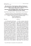
métodos consiste en usar un octocóptero que sobrevuele el campo buscando dichos animales,
como muestra la Figura 1.1.
Figura 1.1: Octocóptero volando
El octocóptero lleva a bordo, entre otros sensores, dos cámaras, una en rango visible y otra
en infrarrojo, conectadas a ordenadores que analizan las imágenes obtenidas. Una vez se ha
detectado el animal, se envía la posición exacta a otro ordenador que se encuentra en tierra. Desde
Linux-driver development for components of the UAV-based fawn detection system
Carmen Eva Ballesteros González
V
R ESUMEN
la centralita en tierra se pueden observar también en tiempo real las imágenes de las cámaras.
Esto es útil no sólo para corroborar la detección de animales, sino también para comprobar
que la imagen obtenida por la cámara térmica es válida, pues es sensible a las condiciones
climatológicas y puede ser necesario tener que reajustar la configuración durante el vuelo.
1.1.2.
Tarea asignada
El objetivo principal del proyecto es desarrollar el software necesario para configurar la
cámara térmica y obtener las medidas del sensor de distancia que lleva a bordo el octocóptero.
Tanto la cámara como el sensor pueden conectarse a través del puerto serie. El ordenador
a bordo no cuenta con más puertos serie disponibles. Sin embargo, cuenta con un bus I2 C que
admite hasta 128 dispositivos conectados.
Para llevar a cabo dicha conexión, es necesario usar una interfaz que haga la conversión
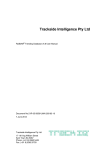
UART ↔ I2 C. El dispositivo usado es el chip SC16IS740 [2]. En la Figura 1.2 se destaca tanto
la conexión entre la cámara térmica (IR Camera) y el ordenador a bordo (Computer-On-Module)
como la conexión entre el sensor de distacia (LDS) y el ordenador. Ambas conexiones se realizan
mediante el conversor UART ↔ I2 C.
IR Camera
UART
UART
I²C ↔ UART
I²C slave
Computer-On-Module
I²C master
I²C
BUS
I²C slave
I²C ↔ UART
UART
LDS
Figura 1.2: Diagrama de las conexiones entre los diversos dispositivos y el ordenador a bordo
del octocóptero, destacando los componentes importantes para el software desarrollado para el
proyecto.
El ordenador a bordo usa como sistema operativo Gumstix Overo Series, que incluye un
kernel Linux. Debido a que no hay drivers disponibles para la interfaz SC16IS740 en Linux, el
software desarrollado en el proyecto debe incluir un driver capaz de manejar dicha interfaz.
Linux-driver development for components of the UAV-based fawn detection system
Carmen Eva Ballesteros González
VI
R ESUMEN
1.2.
Metodología
En kernels monolíticos como Linux, tanto el kernel como todas las subrutinas encargadas
de manejar directamente el hardware se ejecutan en el llamado “kernel space”. Las demás
aplicaciones encargadas de interactuar con el usuario se ejecutan en el llamado “user space”.
Estas aplicaciones sólo pueden interaccionar con el hardware mediante las funciones provistas a
través del “kernel space” [3].
El software requerido debe actuar como puente entre el usuario y el dispositivo que quiera
controlar, ya sea la cámara como el sensor. De esta manera es necesario desarrollar dos tipos
distintos de software para cada dispositivo:
Por un lado es necesario desarrollar un driver que envíe mensajes a través del bus I2C,
configure y controle el conversor UART ↔ I2C.
Por otro lado, hay que desarrollar una aplicación personalizada para cada dispositivo que
controle los mensajes que se le envían, lea la respuesta, y se la haga llegar al usuario.
A continuación se explica el desarrollo de ambos tipos de software:
1.2.1.
Desarrollo del driver en “kernel space”
El driver cuenta con dos partes importantes. Por un lado, para proveer las funciones para
el “user space” necesita contener un character driver. Por otro lado, debe comunicarse con
el dispositivo a través del bus I2 C. Esto puede realizarse usando un i2c driver del i2c core
perteneciente al kernel de Linux [3].
El driver desarrollado se inserta en el kernel mediante insmod. Esto ejecuta una función del
driver llamada module_init(). En dicha función se procede al registro del character driver en el
kernel y del i2c driver en el i2c core. El driver puede ser asímismo retirado del kernel mediante
rmmod, que ejecuta la función module_exit().
Cuando el i2c driver es registrado en el i2c core, éste ejecuta unas determinadas funciones
llamadas probe(), attach_device() y detect_client(). El driver desarrollado se encarga de recopilar
la información concerniente al bus y la dirección del conversor durante la ejecución de dichas
funciones, y la almacena en una estructura llamada i2c_client.
El character driver posee una estructura llamada file_operations con funciones como open(),
close(), write() y read() que pueden ser usadas por aplicaciones. Dichas funciones deben definirse
en el “kernel space”. El driver es desarrollado de manera que en open() se configura la interfaz
UART ↔ I2 C de acuerdo a la configuración del puerto serie del dispositivo al que está conectado.
Tanto open() como write() y read() usan la estructura i2c_client y las funciones provistas por el
i2c core para poder comunicarse a través del bus I2 C.
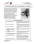
La Figura 1.3 muestra cómo interactúan las estructuras más relevantes dentro del driver.
1.2.2.
Desarrollo de la aplicación en “user space”
Para cada dispositivo se desarrolló una aplicación personalizada. Ambas aplicaciones tienen
la misma estructura. Primero se crea un mensaje que pueda ser reconocido por el dispositivo.
Después se usan las funciones open(), write() y read() para respectivamente configurar el
conversor, enviar el mensaje y leer la respuesta. La respuesta es analizada y en caso de detectarse
algún error vuelve a enviarse el mensaje al dispositivo hasta un máximo de tres veces. Tanto la
respuesta definitiva como los errores en caso de haberlos son reportados al usuario. Antes de
cerrarse la aplicación ejecuta la función close() del driver.
Linux-driver development for components of the UAV-based fawn detection system
Carmen Eva Ballesteros González
VII
R ESUMEN
Figura 1.3: Estructura del driver desarrollado
La cámara admite un código hexadecimal con doble código de comprobación de errores. Esta
codificación es muy poco intuitiva para el usuario, por ello en la aplicación se ha desarrollado
un traductor que convierte mensajes del formato “parámetro valor” a dicho código, y genera
automáticamente el código de comprobación. Igualmente analiza en la respuesta que no haya
habido errores de transmisión y que la cámara haya ejecutado sin problemas el mensaje.
El sensor de distancia es más simple al admitir sólo caracteres que indican si debe realizar una
medida o si debe cambiar entre modo normal y modo de baja energía. La aplicación desarrollada
se encarga de “despertar” al sensor antes de cada medición y volver a dejarlo en modo de baja
energía antes de cerrar la aplicación. De este modo se intenta consumir el mínimo posible de
batería para que la autonomía de vuelo se vea mínimamente afectada.
1.3.
Resultados
Para poder comprobar el funcionamiento del software, primero debe insertarse el driver en el
kernel mediante insmod tau640.ko para la cámara e insmod mlr100.ko para el sensor.
La aplicación de la cámara se ejecuta con comandos que siguen la estructura ./configtau640
parametro valor. La lista con los parametros y rango de valores admitidos por la aplicación se
encuentra en el anexo C de la memoria. La aplicación fue probada conectando un monitor a la
salida de vídeo de la cámara y comprobando que efectivamente la imagen cambiaba de acuerdo
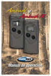
a los comandos introducidos. Como ejemplo, en la Figura 1.4 se muestran diversas capturas tras
probar los valores para el contraste 20, 50 y 70, y debajo de estas líneas se encuentra un ejemplo
del funcionamiento de la aplicación:
root@overo# ./configtau640 contrast 100
Sent: 6e 0 014 0 2605a 0642c22
Answer: 6e 0 014 0 2605a 0642c22
Linux-driver development for components of the UAV-based fawn detection system
Carmen Eva Ballesteros González
VIII
R ESUMEN
Figura 1.4: De izquierda a derecha, imágenes capturadas por la cámara tras cambiar el contraste
a los valores 20, 50 y 70
El funcionamiento de la aplicación del sensor se comprobó tomando medidas con el sensor
conectado al ordenador a bordo. Todas las pruebas fueron satisfactorias comprobando que la
aplicación funciona. A continuación se muestra un ejemplo del funcionamiento de la aplicación:
root@overo# ./mlr100 g
2.04m
1.4.
Conclusiones
El objetivo del proyecto es desarrollar el software necesario para controlar la cámara térmica y
el sensor de distancia que lleva a bordo el octocóptero. Dicho objetivo se completó desarrollando
para cada dispositivo un driver que controle directamente el hardware y una aplicación que
interactúe con el usuario y maneje el driver.
Referencias
[1] Jarnemo, A. (2002). Wildlife Biology, vol. 8. Roe deer Capreolus capreolus fawns and
mowing-mortality rates and countermeasures.
[2] SC16IS740/750/760. Single UART with I2C-bus/SPI interface, 64 bytes of transmit and
receive FIFOs, IrDA SIR built-in support. NXP Semiconductors.
[3] Venkateswaran, Sreekrishnan (2008). Essential linux device drivers. Prentice Hall.
Linux-driver development for components of the UAV-based fawn detection system
Carmen Eva Ballesteros González
IX
R ESUMEN
Linux-driver development for components of the UAV-based fawn detection system
Carmen Eva Ballesteros González
X
LINUX-DRIVER DEVELOPMENT FOR
COMPONENTS OF THE UAV-BASED
FAWN DETECTION SYSTEM
1.1.
Introduction
1.1.1.
Motivation
Every year, circa 100,000 roe deer fawns are killed by the harvesting machines during
mowing actions in Germany, and a total of around 500,000 wild animals die every year in these
conditions [1]. It happens mostly between May and June, coinciding the end of the growing
seasons with the period when the baby deer are born.
The mother leaves the new born fawns in the high grass hidden from their natural predator
while looking for food. During the first three to eight weeks of life, roe deer fawns face danger
situations by remaining instinctively motionless on the ground. The lack of motion, their natural
camouflage and their small size make their detection more difficult.
In order to locate those animals before the mowing, the German Aerospace Center (DLR)
through the Remote Sensing Technology Institute is developing several systems aimed to scan an
area looking automatically for the fawns. One of those methods consists in using an octocopter
that flies over the field looking for those animals, as Figure 1.5 shows.
Figure 1.5: Octocopter flying over a field
Linux-driver development for components of the UAV-based fawn detection system
Carmen Eva Ballesteros González
XI
R ESUMEN
The octocopter carries several sensors and cameras on board. The cameras are a thermal
camera and a visible camera. Both are connected to a Computer-On-Module that analyzes the
images. Once an animal is detected, the computer sends the exact position to another computer
on the ground. From this computer it is also possible to observe the images taken by the cameras
in real time. This is useful not only to corroborate the detection of the animals, but also for
checking that the image taken by the infrared camera is valid for the analysis. This image
depends on the weather conditions and it is usually necessary to readjust the parameters of the
camera during the flight.
1.1.2.
Assigned task
The task of this master thesis consists in developing the necessary drivers that enables the
communication between the Computer-On-Module and the thermal-camera and between the
Computer-On-Module and the laser distance sensor.
The thermal camera as well as the sensor can communicate through a serial port. The
Computer-On-Module has no more serial ports availables. However, it has a I2 C bus that admits
up to 128 I2 C devices connected.
In order to establish this connection, it is necessary to add a UART ↔ I2 C converter. The
chosen interface is the chip SC16IS740 [2]. Figure 1.6 shows the connections between the
components and the computer in the expansion board, and emphasizes the important connectios
for the developed software.
IR Camera
UART
UART
I²C ↔ UART
I²C slave
Computer-On-Module
I²C master
I²C
BUS
I²C slave
I²C ↔ UART
UART
LDS
Figure 1.6: Connection between the COM and both the thermal camera and the laser-distance
sensor
The Computer-On-Module uses Gumstix Overo Series as operating system, that already
includes a Linux kernel. As there is no driver for the SC16IS740 in Linux, it is necessary to
develop a driver to manage the interface and include it in the software.
Linux-driver development for components of the UAV-based fawn detection system
Carmen Eva Ballesteros González
XII
R ESUMEN
1.2.
Methodology
In monolithic kernels as Linux, the kernel runs in kernel mode and the applications in user
mode. Any subroutines or functions forming part of the kernel (modules and device drivers, for
example) are considered to be part of “kernel space”. End-user programs are part of the user
space. When these applications need to interact with the systemâs hardware, they donât do so
directly, but through the kernel supported functions [3].
The required software musts act like bridge between the user and the corresponding device.
Therefore it has been established that the software will be split in two parts:
a module driver in the kernel space to configure the serial port of the UART ↔ I2 C
converter and to control the device,
an application in the user space to interact with the user, personalized for each device.
Hereafter follows an explanation of the development of the software.
1.2.1.
Development of the linux-driver
For this certain situation, there are two important structures required in the driver. On the
one hand, the struct file_operations is typically used to manipulate files. As in UNIX or Linux
systems the devices are seen as files that can be open, closed, written and read, it will be used
in this case to manipulate the device. On the other hand, it is needed an i2c_client to hold the
information of the i2 c device. The kernel already provides some tools collected in the i2c_core
to use the i2 c port, and by adding an i2c_driver with probe and detach functions to bind and
unbind the device, the communication through the i2c port will be easily attained. Therefore it is
necessary to attach the file_operations to the character device, and to register an i2c_driver in the
i2c_core [3].
The developed driver is inserted with the kernel using the command $insmod. It executes the
function of the module driver called module_init(). The task of this function is to register the
char_driver with the kernel and the i2c_driver in the i2c_core. The driver can also be deleted
from the kernel using rmmod, which executes the function module_exit() of the module driver.
Once the i2c_driver is registered in the i2c core, it executes certain functions called probe(),
attach_device() and detect_client(). The driver collects information about the I2C bus and the
address of the I2 C slave together into the struct i2c_client.
The character driver provides the struct file_operations with functions as open(), close(),
write() and read() that can be used by the applications in “user space”. Those functions must be
however defined in “kernel space”. In open() the driver configures the serial port of the UART
↔ I2 C interface in accordance wirh the serial port of the attached device. The open() function as
well as write() and read() use the struct i2c_client and the functions provided by the i2c_core in
order to establish the communication through the i2c port.
Figure 1.7 shows the interaction between the relevant structs of the developed software.
1.2.2.
Development of the applications for “user space”
Although a personalized application was developed for each device, both contain the same
structure. First the application creates a valid message for the device. Later the functions open(),
write() and read() are respectively used for configuring the interface, send the message and read
the answer. The answer is analyzed, and in case of detecting an error, the message is sent again
to the device a maximal of three times. The result as well as the possible error are reported to
Linux-driver development for components of the UAV-based fawn detection system
Carmen Eva Ballesteros González
XIII
R ESUMEN
Figure 1.7: Diagram of the interaction between relevant structs in the developed module driver
the user. Before closing the application, the function close() belonging to the module driver is
executed.
The thermal camera admits a very particular hexadecimal code with double cyclic redundancy
check code. This encoding is not quite user-friendly, therefore the application was developed
with a translator from messages with the format “parameter value” to the aforementioned code,
and also generates automatically the check code. It analyzes as well the answer from the device
looking for transmission errors or problems in the status of the camera.
The laser distance sensor is much simpler as it only admits characters indicating if the sensor
must take a new measurement or change between the normal power mode and the lower power
mode. The sensor can only take measures while the normal power mode is activated. Because
of that, the developed application set the sensor in normal power mode before asking for the
measure.
After receiving the answer from the sensor, the device is set in lower power mode in order to
reduce the consumed power to minimal.
1.3.
Results
In order to test the developed software it is necessary to insert first both drivers with the
kernel, using insmod tau640.ko for the camera and insmod mlr100.ko for the sensor.
The application of the camera is executed using the structure ./configtau640 parameter value.
A list with all the parameters and values range admitted by the application for the thermal camera
is allocated in Appendix C on the report of the thesis. The application was tested connecting
a monitor to the video output of the camera, and checking that the entered commands actually
change the image in an expected way. Figure 1.8 helps to visualize the difference between three
different contrast values in the image captured by the camera, and the following code is an
example of setting the contrast with the value 100:
root@overo# ./configtau640 contrast 100
Sent: 6e 0 014 0 2605a 0642c22
Answer: 6e 0 014 0 2605a 0642c22
Linux-driver development for components of the UAV-based fawn detection system
Carmen Eva Ballesteros González
XIV
R ESUMEN
Figure 1.8: From left to right, captured images with contrast 20, 50 and 70
The application for the laser distance sensor was tested by taking measurements with the
sensor connected to the Computer-On-Module. All the tests resulted satisfactory proving that
the application works correctly. The following code is an example of the application taking
measurements:
root@overo# ./mlr100 g
2.04m
1.4.
Conclusions
Aim of the thesis was to developed the required software for controlling the thermal camera
and laser distance sensor at the octocopter. The mentioned aim was full filled developing a driver
that controls the communication with the device and a personalized application for eah device
that interacts with the user and manages the developed driver.
Bibliography
[1] Jarnemo, A. (2002). Wildlife Biology, vol. 8. Roe deer Capreolus capreolus fawns and
mowing-mortality rates and countermeasures.
[2] SC16IS740/750/760. Single UART with I2C-bus/SPI interface, 64 bytes of transmit and
receive FIFOs, IrDA SIR built-in support. NXP Semiconductors.
[3] Venkateswaran, Sreekrishnan (2008). Essential linux device drivers. Prentice Hall.
Linux-driver development for components of the UAV-based fawn detection system
Carmen Eva Ballesteros González
XV
R ESUMEN
Linux-driver development for components of the UAV-based fawn detection system
Carmen Eva Ballesteros González
XVI
Abstract
Every year, just in Germany around 100,000 roe deer fawns are killed by the harvesting
machines during the mowing actions [JARNEMO, 2002]. During the silage, the carcasses of those
animals is accidentally mixed with the crop and given as fodder for the dairy cattle, producing
them a paralytic illness. This fact harms the agrarian sector by causing huge economical losses.
The German Aerospace Center (DLR) is developing several systems aimed to scan an area
looking automatically for the fawns [I SRAEL, 2010a]. One of those methods is using an UAV
(unmanned aerial vehicle) based system that carries a computer-on-module with several sensors,
including a thermal infrared camera, a RGB-camera and a laser-distance sensor.
The main scope of this master thesis consists in developing the necessary drivers that enables
the communication between the computer-on-module and:
1. the thermal-camera
2. the laser-distance sensor
The communication is not direct. An interface that converts from UART to I2 C connects the
serial port of each sensor with the computer-on-module via I2 C bus. The driver must manage the
added interface and act like a bridge between the user and the sensors.
An application for each sensor is also developed, in order to facilitate the user to control both
devices.
Linux-driver development for components of the UAV-based fawn detection system
Carmen Eva Ballesteros González
XVII
A mis padres, por ayudarme a cumplir mis objetivos
como persona y estudiante, por brindarme los recursos
necesarios, confiar en mis decisiones y haberme
aconsejado siempre que lo he necesitado.
A mis abuelos Engraciano y Carmen, a los que admiro,
por todo el cariño y ánimo recibidos, haber creido
siempre en mi, y por servirme como motivación e impulso
para hacer realidad mis sueños.
Y finalmente a mi hermano por saber comprenderme, haberme
servido de apoyo cuando lo he necesitado y tener la
habilidad de sacarme una sonrisa incluso en los momentos
más difíciles.
Acknowledgements
Foremost, I am heartily thankful to my supervisor at DLR, Dipl.-Ing. Martin Israel, for his
patience, motivation, enthusiasm, and expertise. He has made available his support in a number
of ways, and provided me guidance and assistance from the initial to the final level of this project.
I would like to thank my supervisor at Technische Universität Darmstadt, Dipl.-Ing. Kerstin
Gross, for her patience and friendly help.
I am grateful to Dr.-Ing. Peter Haschberger for his supervision and valuable advice.
I wish to extend my sincere gratitude to Dipl.-Ing. Philipp Neugebauer, and all preceding
graduate students, for their previous work that made possible the development of my master
thesis.
I am grateful to DLR and specially the Institut für Methodik der Fernerkundung, that provided
the support and equipment I needed to produce and complete my work.
Lastly, I would like to show my gratitude to my colleagues and staff in DLR for the use of
facilities in the Lab, and for providing a friendly environment for working, a coffee machine and
moral support.
Linux-driver development for components of the UAV-based fawn detection system
Carmen Eva Ballesteros González
XIX
ACKNOWLEDGEMENTS
Linux-driver development for components of the UAV-based fawn detection system
Carmen Eva Ballesteros González
XX
ML
DOCUMENT I
REPORT
D OCUMENT I. R EPORT § I NDEX
Linux-driver development for components of the UAV-based fawn detection system
Carmen Eva Ballesteros González
2
Index
I.
Report
1. Introduction
1.1. Problem situation and motivation . . . . .
1.2. Previous methods of resolution . . . . . .
1.3. UAV-based fawn detection system . . . .
1.3.1. Octocopter platform . . . . . . . . . .
1.3.2. Hardware components . . . . . . . .
1.3.3. Software . . . . . . . . . . . . . . . .
1.4. Assignment situation and task structuring
11
.
.
.
.
.
.
.
.
.
.
.
.
.
.
.
.
.
.
.
.
.
.
.
.
.
.
.
.
.
.
.
.
.
.
.
.
.
.
.
.
.
.
.
.
.
.
.
.
.
.
.
.
.
.
.
.
.
.
.
.
.
.
.
.
.
.
.
.
.
.
2. Development of the test environment
2.1. Hardware tools . . . . . . . . . . . . . . . . . . . . . . . .
2.1.1. USB-I2C converter . . . . . . . . . . . . . . . . . . . .
2.1.2. UART-USB converter . . . . . . . . . . . . . . . . . . .
2.2. Software tools . . . . . . . . . . . . . . . . . . . . . . . . .
2.2.1. Communication tools . . . . . . . . . . . . . . . . . . .
2.2.1.1. Kermit . . . . . . . . . . . . . . . . . . . . . . . .
2.2.1.2. HTerm . . . . . . . . . . . . . . . . . . . . . . . .
2.2.2. TAU640 thermal camera connected to the computer . . .
2.2.3. MLR100 laser distance sensor connected to the computer
2.2.4. Cross Compiler . . . . . . . . . . . . . . . . . . . . . .
.
.
.
.
.
.
.
.
.
.
.
.
.
.
.
.
.
.
.
.
.
.
.
.
.
.
.
.
.
.
.
.
.
.
3. Development of the Linux-driver
3.1. SC16IS740 Chip . . . . . . . . . . . . . . . . . . . . . . . . .
3.1.1. I2 C . . . . . . . . . . . . . . . . . . . . . . . . . . . . . . .
3.1.2. UART . . . . . . . . . . . . . . . . . . . . . . . . . . . . .
3.1.3. UART configuration for the SC16IS740 . . . . . . . . . . .
3.2. Development of the specific software for controlling both devices
3.2.1. Character Driver in kernel space . . . . . . . . . . . . . . .
3.2.2. User Application for the thermal-camera TAU640 . . . . . .
3.2.3. User Application for the laser-distance sensor MLR100 . . .
3.3. Generic Terminal Driver for SC16IS740 . . . . . . . . . . . . .
4. Results
4.1. Preliminary tests . . . . . . . . . . . . . . .
4.1.1. Tests with the help of an oscilloscope .
4.1.2. Tests connecting the EB to the computer
4.2. Test connecting EB to the actual devices . .
4.2.1. Test connecting EB to TAU640 . . . . .
4.2.2. Test connecting EB to MLR100 . . . .
.
.
.
.
.
.
.
.
.
.
.
.
.
.
.
.
.
.
.
.
.
.
.
.
.
.
.
.
.
.
.
.
.
.
.
.
.
.
.
.
.
.
.
.
.
.
.
.
Linux-driver development for components of the UAV-based fawn detection system
Carmen Eva Ballesteros González
.
.
.
.
.
.
.
.
.
.
.
.
.
.
.
.
.
.
.
.
.
.
.
.
.
.
.
.
.
.
.
.
.
.
.
.
.
.
.
.
.
.
.
.
.
.
.
.
.
.
.
.
.
.
.
.
.
.
.
.
.
.
.
.
.
.
.
.
.
.
.
.
.
.
.
.
.
.
.
.
.
.
.
.
.
.
.
.
.
.
.
.
.
.
.
.
.
.
.
.
.
.
.
.
.
.
.
.
.
.
.
.
.
.
.
.
.
.
.
.
.
.
.
.
.
.
.
.
.
.
.
.
.
.
.
.
.
.
.
.
.
.
.
.
.
.
.
.
.
.
.
.
.
.
.
.
.
.
.
.
.
.
.
.
.
.
.
.
.
.
.
.
.
.
.
.
.
.
.
.
.
.
.
.
.
.
.
.
.
.
.
.
.
.
.
.
.
.
.
.
.
.
.
.
.
.
.
.
.
.
.
.
.
.
.
.
.
.
.
.
.
.
.
.
.
.
.
.
.
.
.
.
.
.
.
.
.
.
.
.
.
.
.
.
.
.
.
.
.
13
13
13
17
17
18
21
22
.
.
.
.
.
.
.
.
.
.
25
25
26
27
28
28
28
29
29
30
32
.
.
.
.
.
.
.
.
.
35
36
37
40
40
43
43
48
49
50
.
.
.
.
.
.
53
53
53
54
56
57
58
3
D OCUMENT I. R EPORT § I NDEX
5. Conclusion and outlook
5.1. Analysis of the developed software . . . . . . . . . . . . . . . . . . . . . . . .
5.2. Possible future improvements . . . . . . . . . . . . . . . . . . . . . . . . . . .
59
59
60
References
62
II. User Manual
65
1. How to configure the settings of the serial port in the driver
67
2. How to create an application for the driver
69
3. Commands for the TAU640 camera
71
4. Application for the laser-distance sensor MLR100
73
Linux-driver development for components of the UAV-based fawn detection system
Carmen Eva Ballesteros González
4
List of Figures
1.1.
Geometrical conditions in the search of deer fawn. To find it, the person must be in
a close proximity from 1 to 2 meters (Source: [I SRAEL, 2011a]). . . . . . . . . . . 14
1.2. People carrying the portable rescue-system (Source: [H ARDER, 2008]) . . . . . . 15
1.3. Design of mower with extension arm (Source: [I SRAEL, 2010b]) . . . . . . . . . 15
1.4. Testing model of extension arm incorporated in mower (Source: [I SRAEL, 2010a]) 15
1.5. Principle of the double-radar (Source: [A. FACKELMEIER, 2009]) . . . . . . . . . 16
1.6. Terrain covered by the UAV when flying at an altitude of 50 meters (Source:
[I SRAEL, 2011a]). . . . . . . . . . . . . . . . . . . . . . . . . . . . . . . . . . . 17
1.7. The flight-plan of the UAV is designed to fly always at the same altitude taking as
reference the start position. In sloping terrains this affects to the image processing
as the scale changes (Source: [I SRAEL, 2011a]). . . . . . . . . . . . . . . . . . . 18
1.8. Falcon 8 model flying over a field (Source: [I SRAEL, 2011b]) . . . . . . . . . . . 18
1.9. Gumstix Overo COM (Source: www.gumstix.com) . . . . . . . . . . . . . . . . . 19
1.10. Block diagram of the Expansion-Board . . . . . . . . . . . . . . . . . . . . . . . 21
1.11. Front and back picture of the EB with all components assembled (Source:
[N EUGEBAUER, 2011]) . . . . . . . . . . . . . . . . . . . . . . . . . . . . . . . 21
1.12. Connection between the COM and both the thermal camera and the laser-distance
sensor . . . . . . . . . . . . . . . . . . . . . . . . . . . . . . . . . . . . . . . . . 23
2.1. SC16IS740 connected to a PC using both USB-I2C and UART-USB converter . . 26
2.2. ELV USB-I2C (Source: [ELV, 2010]) . . . . . . . . . . . . . . . . . . . . . . . . 26
2.3. Pin configuration of the PCA9517 . . . . . . . . . . . . . . . . . . . . . . . . . . 27
2.4. Connection lines only related with the I2 C-port of the circuit that connects the
SC16IS740 chip with a PC . . . . . . . . . . . . . . . . . . . . . . . . . . . . . . 27
2.5. Connection lines only related with the UART of the circuit that connects the
SC16IS740 chip with a PC . . . . . . . . . . . . . . . . . . . . . . . . . . . . . . 28
2.6. HTerm 0.8.1 beta . . . . . . . . . . . . . . . . . . . . . . . . . . . . . . . . . . . 30
2.7. Setup Tab and AGC Tab of the FLIR Camera Controller GUI (Source: [Tau, October 2010]) 31
2.8. Interface Adapter Board of the MLR100 sensor with the pins from the UART
numbered . . . . . . . . . . . . . . . . . . . . . . . . . . . . . . . . . . . . . . . 31
3.1. Interaction-layers between user and hardware . . . . . . . . . . . . . . . . . . . . 35
3.2. The aim of the generic driver is that the user can communicate through it as it were a
serial port. The user would interact with the attached device using a communication
tool (see section 2.2.1) that needs to be configured for the certain device attached to
the chip. The developed driver is specified for the attached device and manages it
in an optimal way. The user interacts directly with the device through the application. 36
3.3. Pin configuration for TSSOP16 with I2 C-bus interface . . . . . . . . . . . . . . . 37
3.4. Connection between COM, SC16IS740 chips and the corresponding devices . . . 37
3.5. Global diagram of the interaction of the different layers in the developed software
both in kernel and user space . . . . . . . . . . . . . . . . . . . . . . . . . . . . . 44
3.6. Diagram of the driver in kernel space . . . . . . . . . . . . . . . . . . . . . . . . 44
Linux-driver development for components of the UAV-based fawn detection system
Carmen Eva Ballesteros González
5
D OCUMENT I. R EPORT § I NDEX OF F IGURES
3.7.
4.1.
4.2.
4.3.
4.4.
4.5.
4.6.
5.1.
5.2.
Global diagram of the different tools interacting in the generic driver for SC16IS740 51
Loading the Gumstix Overo System . . . . . . . . . . . . . . . . . . . . . . . . . 54
General view of the back side of the Expansion-Board. (Source [N EUGEBAUER, 2011]) 55
General view of the front side of the Expansion-Board. (Source [N EUGEBAUER, 2011]) 55
Oscilloscope measure at the pin 6 of the SC16IS740 chip while configuring the
serial port of the interface. . . . . . . . . . . . . . . . . . . . . . . . . . . . . . . 56
Hterm and a terminal . . . . . . . . . . . . . . . . . . . . . . . . . . . . . . . . . 56
From left to right, captured image with contrast 20, 50 and 70 . . . . . . . . . . . 58
Connection between the COM and the devices through the SC16IS740 interface . 59
Diagram of the layers in the developed software . . . . . . . . . . . . . . . . . . 60
Linux-driver development for components of the UAV-based fawn detection system
Carmen Eva Ballesteros González
6
List of Tables
1.1.
2.1.
2.2.
3.1.
3.2.
3.3.
3.4.
3.5.
1.1.
3.1.
4.1.
Port settings of the RS-232 serial interface of the camera TAU 640 . . . . . . . . .
TTL-232R-PCB Input / Output Descriptions . . . . . . . . . . . . . . . . . . . .
Pin Definition for the connection between MLR100 and a PC . . . . . . . . . . .
SC16IS740 address map [SC1, 2011] . . . . . . . . . . . . . . . . . . . . . . . .
SC16IS740 register address byte [SC1, 2011] . . . . . . . . . . . . . . . . . . . .
Baud rates of the SC16IS740 using a 1.8432 MHz crystal [SC1, 2011] . . . . . . .
This table set the register address of the different registers used in this section,
according to table 3.2 and the register id. . . . . . . . . . . . . . . . . . . . . . .
Status Byte . . . . . . . . . . . . . . . . . . . . . . . . . . . . . . . . . . . . . .
Register address byte for the internal registers in SC16IS740 [SC1, 2011] . . . . .
Table with the available function commands in the application for the TAU640 camera
Arguments admitted by the application for the laser-distance sensor MLR100 . . .
Linux-driver development for components of the UAV-based fawn detection system
Carmen Eva Ballesteros González
20
28
32
39
39
41
41
48
67
72
73
7
D OCUMENT I. R EPORT § I NDEX OF TABLES
Linux-driver development for components of the UAV-based fawn detection system
Carmen Eva Ballesteros González
8
List of Abbreviations
A/D
ACK
API
BC
CCITT
CH
CMOS
COM
CR
CRC
CTS
DLH
DLL
EB
EN
I2 C
ICAI
IR
IrDA
FC
FCR
FFC
FIFO
GND
GPIO
GPS
GUI
LCR
LDISC
LDS
LF
LSB
LVDS
MMC
MSB
NA
OE
OS
OTG
PC
Analog/Digital
Acknowledge
Application programming interface
Byte Count
International Telegraph and Telephone Consultative Committee
Channel
Complementary Metal Oxide Semiconductor
Computer-on-module
Carriage Return
Cyclic Redundancy Check
Clear To Send
Divisor Latch MSB
Divisor Latch LSB
Expansion-board
Enable
Inter-Integrated Circuit
Insitituto Católico de Artes e Industrias
Infrared
Infrared Data Association
Function Code
FIFO Control Register
Flat-Flex Cable
First In First Out
Ground
General Purpose Input Output
Global Position System
Graphic User Interface
Line Control Register
Line Discipline
Laser-distance sensor
Line Feed
Less Significant Bit
Low-voltage differential signaling
Multimedia Card
Most Significant Bit
Negative Acknowledge
OpenEmbedded
Operating System
On-The-Go
Personal Computer
Linux-driver development for components of the UAV-based fawn detection system
Carmen Eva Ballesteros González
9
D OCUMENT I. R EPORT § L IST OF A BBREVIATIONS
PCB
PFC
PWM
RGB
RTS
RX
SCL
SDA
SMBus
SPI
TTL
TTY
TX
UART
USB
Printed circuit board
Proyecto Fin de Carrera
Pulse-Width Modulation
Red, green and blue
Request To Send
Receive
Serial Clock
Serial Data
System Management Bus
Serial Peripheral Interface
Transistor-transistor Logic
Teletypewritter
Transmit
Universal Asynchronous Receiver Transmitter
Universal Serial Bus
Linux-driver development for components of the UAV-based fawn detection system
Carmen Eva Ballesteros González
10
ML
PART I
REPORT
Chapter 1
Introduction
1.1.
Problem situation and motivation
Every year, circa 100,000 roe deer fawns are killed by the harvesting machines during mowing
actions in Germany [JARNEMO, 2002]. A total of around 500,000 wild animals die every year
in these conditions [C ERRA, 2009]. It happens mostly between May and June, coinciding the
end of the growing seasons with the period when the baby deer are born. The mother leaves
the new born fawns in the high grass hidden from their natural predator while looking for food.
During the first three to eight weeks of life, roe deer fawns face danger situations by remaining
instinctively motionless on the ground. The lack of motion, their natural camouflage and their
small size make their detection more difficult.
Other animals like rabbits and brooding birds are also victims of the harvesting machines.
Even for adult wild animals it is difficult to escape from the commonly operating width of 6-14
meters and the operating speed of 12-20 km/h [K URT, 1968]. For the agriculturist it is impossible
to detect the fawns from the harvesting machine, and this situation leads to a distressful death of
the animals [M UERI, 1999, I SRAEL, 2010a].
During the silage the carcasses of those animals is mixed with the crop, and later it is given
as fodder for the dairy cattle.
Temperatures over 25◦ C within a protein-full hermetically sealed environment conforms
an ideal culture medium for the “Clostridium botulinum” bacterium. This bacterium produces
the “Botulinum toxin”, which is considered the most powerful neurotoxin ever discovered. An
amount between 0.1 and 1 micrograms of this protein is enough to kill an adult person. Getting
the carcass into the harvest, keeping it inside a silo and getting warm because of the fermentation
fulfills the requirements that create the poison [H OLZHAUER, 2009].
Once the dairy cattle consume the contaminated fodder, they get a paralytic illness called
“Botulism”. This kind of intoxication is usually deadly and not directly treatable. In a dairy farm
this could mean the death of the animal, or in extreme cases the death of the whole herd. The
economical losses are huge for the farm.
From an economical and also moral point of view, it is necessary to develop a system capable
of detecting the roe deer fawns in time.
1.2.
Previous methods of resolution
Several methods to avoid the killing of those animals during the harvest were proven, in
order to let the agriculturist mow their field risk-less. The following methods of resolution were
so far prosecuted:
Linux-driver development for components of the UAV-based fawn detection system
Carmen Eva Ballesteros González
13
I. R EPORT § 1. I NTRODUCTION
Mechanical rescue-system mounted at the mowing machine
Years ago a mechanical device with the form of tines was attached in the front of the mower,
preventing the machine taking the wild animals by lifting them instead and therefore saving
them. This method is no longer effective nor found in today’s agriculture technology.
Instead nowadays it is used a horizontal arm with pipes or chains vertically attached that
sweeps the following lane flushing out the wild animals.
Combing with dogs
Another option is scanning the field before mowing. Dogs are really useful in this case
because of their sense of smell, and they can be trained to perceive the smell of the deer
fawns and then scare them. This method has however a disadvantage. It takes a lot of
time to trail a whole field, even with multiple searchers. The aggravating factor of the
geometrical conditions showed in Figure 1.1 should be also taken into account. At an
average vegetation height of one meter, a 0.3 meter long deer fawn can be found by a 1.7
meter tall searcher if it is inside a radius of 0.5 meters. The higher the grass is, the more
difficult it is to find the fawn. If there is grass over the fawn, even just being half a meter
away might not be enough.
Figure 1.1: Geometrical conditions in the search of deer fawn. To find it, the person must be in
a close proximity from 1 to 2 meters (Source: [I SRAEL, 2011a]).
In order to locate those animals before the mowing, the German Aerospace Center (DLR)
through the Remote Sensing Technology Institute is developing several systems aimed to scan
an area looking automatically for the fawns. [I SRAEL, 2010a]
Portable rescue-system
DLR developed and patented a portable rescue-system in 1987. Ten years ago it was
introduced in the market by i_s_a1 . The rescue-system consists of a telescopic handle that,
thanks to ten infrared sensors, can be used to cover a width of six meters, as shown in Fig
1.2. This system can quickly scan the closer ground. On cloudy days or during the early
morning and late evening, the system works with a high reliability. On the other hand,
with a strong sunlight the sensors will be limited and fawns can no longer be distinguished
from other objects (such as mounds or molehills).
1
distribution by: isa Industrieelektronik GmbH | www.isaweiden.de | www.wildretter.de
Linux-driver development for components of the UAV-based fawn detection system
Carmen Eva Ballesteros González
14
I. R EPORT § 1. I NTRODUCTION
Figure 1.2: People carrying the portable rescue-system (Source: [H ARDER, 2008])
Extension arm / sensors at the mowing machine
More recent developments and researches engage in adding appropriate sensors directly to
the agricultural machine, as shown in Figure 1.3. The first prototype is a cantilever arm,
mounted on the mower, that scans the following swath looking for wild animals from a
height of 1.2 meters. The signal is processed before the mower reaches the scanned swath.
In the experiment shown in Figure 1.4, infrared sensors, microwave sensors, distance
sensors, infrared cameras and cameras with visible spectral range are combined for this
purpose. Experience has shown that a camera-based system is unfavorably because of the
high-speed of the mowing machine considering the low height it is assembled at and the
vibrations caused by the terrain. Infrared, microwave and proximity sensors look more
promising and therefore will be traced.
Figure 1.3: Design of mower with extension
arm (Source: [I SRAEL, 2010b])
Figure 1.4: Testing model of extension arm
incorporated in mower (Source:
[I SRAEL, 2010a])
Microwave sensors can detect objects that contain a considerable amount of water. The
extension arm uses this kind of sensors to detect deer fawns in the swath of grassland.
The sensor has a certain angle of incidence, as shown in Figure 1.5, to detect the reflected
Linux-driver development for components of the UAV-based fawn detection system
Carmen Eva Ballesteros González
15
I. R EPORT § 1. I NTRODUCTION
waves. The slope angle has as advantage that the receptor won’t receive the reflected
microwaves from the ground or puddles, but isolated objects as deer fawns can be easily
distinguished from ground and therefore detected.
Radar sensors
Direction of motion
Reflexion of the
ground
Antenna
a
Reflected from
target figure
Volume variation
of the vegetation
Vegetation
fawn
Ground
Figure 1.5: Principle of the double-radar (Source: [A. FACKELMEIER, 2009])
Another possibility is to assemble the sensors directly on the mowing machine with a
front-facing orientation looking at the current swath. The geometrical problem explained
in the “Trailing with dogs” section would be also applied here, reaching the conclusion
that placing infrared sensors is more effective than a camera system in order to detect a
fawn lying on the ground.
UAV-based system
The last method consists in using an UAV (unmanned aerial vehicle) based system that
carries a computer-on-module with several sensors. The main sensors of the measurement
hardware on board are a thermal infrared camera and a camera for the visible region. Under
certain weather conditions it is difficult to distinguish in the infrared image an animal from
something else that reflects the solar light. The visible camera is used to compare both
images in order to make the detection more precise.
The cruising altitude can be chosen between 30 meters and 50 meters. As Fig. 1.6 shows,
at an altitude of 50 meters the images taken from the UAV cover an area of 27 meter of
diameter. This reduces significantly the necessary time to track the whole field. Weather
conditions determine the optimal moment for harvesting the field. Therefore, under certain
conditions, a whole region can be harvested in a few days. In this case time is crucial to
track as much terrain as possible.
The UAV plans the flight with the help of a GPS and the Google Maps Elevation API. In
order to verify the accuracy of the API, it is also equipped with a laser distance sensor
for measuring the distance to the ground during the flight. This is also important because
the UAV is programmed to fly always at the same altitude taking as reference the start
position. In sloping terrains the actual distance to the ground can change, as shown in Fig.
1.7, and therefore the scale of the image would be different. For the image processing it is
essential to know the actual scale of the image.
Linux-driver development for components of the UAV-based fawn detection system
Carmen Eva Ballesteros González
16
I. R EPORT § 1. I NTRODUCTION
Figure 1.6: Terrain covered by the UAV when flying at an altitude of 50 meters (Source:
[I SRAEL, 2011a]).
1.3.
UAV-based fawn detection system
This project is focused in the development of software for the UAV-based fawn detection
system.
The vehicle uses as main structure the Octocopter Falcon 8 developed by Ascending
Technologies GmbH. The core of the detection-system is a small computer-on-module (COM)
which takes over the data-processing. A thermal and a RGB-camera are the main sensors attached
to the system. In general all sensors are connected to the COM through an expansion-board
(EB).
Hereafter follows a more detailed description of the components.
1.3.1.
Octocopter platform
The platform of the UAV is an octocopter system developed by Ascending Technologies
GmbH 2 . The called Falcon 8 model is specially designed for air-photography and to inspect and
get data during the flight. The model flying can be seen in Fig. 1.8.
The eight actuators (combination of rotor and motor) give the UAV a high stability and skill
to hold winds with a maximal speed of 10 m/s. The stability is reinforced by an integrated control
system, using the measures of multiple electronic sensors like a GPS, gyroscope, barometric
height sensors, compass and velocity sensors.
2
http://www.asctec.de
Linux-driver development for components of the UAV-based fawn detection system
Carmen Eva Ballesteros González
17
I. R EPORT § 1. I NTRODUCTION
Constant
flight
altitude
Start
position
Figure 1.7: The flight-plan of the UAV is designed to fly always at the same altitude taking as
reference the start position. In sloping terrains this affects to the image processing as the scale
changes (Source: [I SRAEL, 2011a]).
Figure 1.8: Falcon 8 model flying over a field (Source: [I SRAEL, 2011b])
The octocopter includes also an autopilot software developed by AscTec, that in combination
with the waypoint planning software developed by DLR allows the UAV to fly over a given area
scanning efficiently the terrain.
1.3.2.
Hardware components
1. Computer-on-module
Linux-driver development for components of the UAV-based fawn detection system
Carmen Eva Ballesteros González
18
I. R EPORT § 1. I NTRODUCTION
The core of the measure system is a small Computer-on-module (COM) developed by
Gumstix 3 . Its specifications are detailed in Figure 1.9
Processor OMAP35xx with Cortex-A8
CPU velocity 600 MHz or 720 MHz
Memory 512 MB or 256 MB Low-Power DDR
RAM; 256 MB NAND Flash
On the board Micro SD Slot
Dimensions 58 mm x 17 mm x 4.4 mm
Weight 6 g
Figure 1.9: Gumstix Overo COM (Source: www.gumstix.com)
The COM counts with one 27-pin Flat-Flex Cable (FFC) connection, which is located
on the upper side of the module and provides a digital video interface for connection
of cameras, two u.fl antenna connectors and two 70-pin AVX 5602 Board-To-Board
Connectors that makes a total of 140 signals for GPIOs, I2 C, 6 PWM lines, 6 A/D, 1-wire,
UART, SPI, Extra MMC lines, Headset, Microphone, Backup battery, High Speed USB
Host and USB OTG.
2. Thermal-camera
The thermal camera is the model TAU 640 from the company FLIR Commercial Systems
4
. This camera covers almost the whole long-wavelength infrared region detecting
wavelengths from 8 to 14 µm.
Configuration and remote control is provided via a RS-232 serial interface consisting of
signals named RX, TX and GND using 3.3 volt signal levels. Outgoing messages are only
generated as a response of each incoming command. The serial port settings are shown in
Table 1.1.
The real-time digital video is provided by a digital parallel channel. The XP-Bus may be
configured through software for three different digital data channels:
The BT.656 channel transmits pixels in a video data signal format called YUV, that
contains image, symbol, and color information.
The CMOS channel is a parallel image data output. The raw-data are directly sent,
not requiring transference or conversion via a video capture card.
The serial low-voltage differential signaling (LVDS). This channel consists of three
signal lines: a clock, a composite sync (frame sync and data valid), and serial data.
The camera is connected to the computer-on-module through two communication lines.
The RS-232 serial interface used for the configuration is connected through a UART-I2 C
converter (SC16IS740) to one of the I2 C connectors of the COM. The digital video data
travels through the 27-pin Flat-Flex Cable (FFC) connection. The chosen digital data
channel will be the BT.656.
3
4
http://www.gumstix.com
http://www.flir.com/cvs/cores/view/?id=51374
Linux-driver development for components of the UAV-based fawn detection system
Carmen Eva Ballesteros González
19
I. R EPORT § 1. I NTRODUCTION
Parameter
Baud rate
Data bits
Parity
Stop bits
Flow control
Value
57600
8
None
1
None
Table 1.1: Port settings of the RS-232 serial interface of the camera TAU 640
3. RGB-camera
It is also necessary to add a RGB-camera to the octocopter in order to collect color
pictures to contrast them with the infrared ones. The choice is a 5 megapixels camera
(e-CAM50_OMAP_GSTIX) from e-con Systems, specifically developed and built for the
COM of the Gumstix’s Overo Series. The configuration is done through an I2 C interface
and, as happens with the thermal camera, the video data travels through the 27-pin FlatFlex Cable (FFC) connection. In order to let both thermal camera and RGB-camera use
the FFC, a 2:1 multiplexer controlled by the COM will choose which data the Gumstix
system will receive and analyze.
4. Laser-distance sensor
The laser-distance sensor (LDS) will be used to measure the height at which the octocopter
is flying, in order to verify the accuracy of the Google Maps Elevation API. The chosen
sensor is the model MLR100 developed by Aerius Photonics, LLC. It has a long range
capability from ∼0 m to 100 m with a resolution better than 20 cm. The LDS is connected
through a RS-232 serial interface to the I2 C Bus from the COM. In order to make this
connection capable, a UART-I2 C converter (SC16IS740) will be used.
5. Expansion-Board
In order to connect the COM with the remaining hardware components, it was necessary
to develop an expansion-board (EB). The task was carried out during a previous master
thesis [N EUGEBAUER, 2011]. For its design several factors had been considered.
From the structural side, the optimization resides in the minimum weight and size as well
as an optimal physical distribution of the components all along the expansion-board.
Because of the different specifications of the elements in the EB and the other hardware
components, it was also necessary to implement level-shifters, inverters and converters.
Another important factor in the design is the power supply. The required voltage changes
from one element to another, making it necessary the existence of 1.8V, 3.3V and 5V
sources. The EB is fed with a voltage supply of 5V. Internal voltage converters provide
the remaining 3.3V and 1.8V. In the octocopter the power supply comes from a lithium
polymer battery.
Figure 1.10 shows the block diagram of the EB.
An overall front and back picture with the components assembled is shown in figure 1.11
Linux-driver development for components of the UAV-based fawn detection system
Carmen Eva Ballesteros González
20
I. R EPORT § 1. I NTRODUCTION
IR Camera
UART (inv)
Digital
Video
Invert
LevelShifter
UART
I²C ↔ UART
Digital
Video
I²C
Console
Port
UART
USB
Host
USB
Computer-On-Module
3V
GPIOs
TV Out
1,8V
3,3V
Power
Supply
Backup
Battery
UART
I²C
BUS
I²C
UART
I²C
I²C ↔ UART
GPIOs
EEPROM
LevelShifter
5V
LevelShifter
UART
RS232
Tranceiver
LED/Taster
Falcon 8
Connector
RS232
LDS
Figure 1.10: Block diagram of the Expansion-Board
Figure 1.11: Front and back picture of the EB with all components assembled (Source:
[N EUGEBAUER, 2011])
1.3.3.
Software
The Gumstix Overo Series uses the Linux Kernel Image 2.6.34 and provides a software
bundle and a base system out-of-the-box (i.e. it doesn’t require any additional installation). It also
utilizes a build environment with cross-compilation support called Linuxr OpenEmbedded (OE),
that creates Linux distributions by producing root file systems, packages and custom software,
Linux-driver development for components of the UAV-based fawn detection system
Carmen Eva Ballesteros González
21
I. R EPORT § 1. I NTRODUCTION
and can build many of existing open source libraries and tools useful on and for embedded
systems.
The heart of OE is Bitbake, a tool that resolves dependencies between different software
packages in order to build a complete embedded system. For that purpose the tool needs a basic
recipe consisting of a configuration file with information about the sources, the dependencies as
well as some options the compilation and the installation need. The OE environment uses this
information in order to assemble the package to the complete build system.
A more detailed explanation about how the cross compiler works and how it was used for the
development of the drivers can be found in section 2.2.4 Cross Compiler.
1.4.
Assignment situation and task structuring
The task of this master thesis consists in developing the necessary drivers that enables the
communication between the COM and the thermal-camera and between the COM and the
laser-distance sensor.
The need of this communication stems from two different reasons. On the one hand, the
height of the sun, certain weather conditions and the terrain characteristics have influence on the
parameters of the thermal camera such as to optimize the detection of deer fawns. Therefore the
parameters need to be often readjusted. On the other hand, as explained before in Fig. 1.7, it is
important to know the scale of an image when processing it. In sloping terrains the height at
which the image is taken can vary, affecting the scale.
The connection of both components to the COM is not direct. Both devices can only
communicate through serial ports, but there are no more available UART connections at the
COM, so it becomes necessary to find another way to connect both devices to other ports of
the COM. With the help of a UART-to-I2 C converter the components can be connected to the
still available I2 C ports of the COM. The responsible chip for the conversion is the SC16IS740
interface [SC1, 2011]. Figure 1.12 marks the relevant hardware for the task.
Therefore the software must be executed in the Gumstix System that uses the Linux Kernel,
and it must be capable of communicating with the SC16IS740 through the I2 C-bus, configuring
the serial port of the chip and establishing a communication with the attached device.
Before developing the software some preliminary work is necessary. First of all it is
recommended to test the SC16IS740 interface alone. This task is achieved by connecting
both sides of the interface to a computer. Besides there is also a software environment and
some tools required for the development of software for the Gumstix System. The necessary
software and hardware to achieve the test, as well as the software tools required to later develop
the software, are explained in Chapter 2.
The next step is developing the software. In monolithic kernels as Linux, the kernel runs
in kernel mode and the applications in user mode. Therefore it has been established that the
software will be split in two parts:
a driver in the kernel space to control the device. It controls the communication with the
hardware and configures the port setting of the UART at the SC16IS740.
an application in the user space to interact with the user. It is personalized for each device.
The information of how the software is developed remains in Chapter 3. The obtained results
are explained in Chapter 4. User manuals for the drivers and applications developed lies as
appendixes. Appendix 1 explains how to configure the serial port settings in driver for the
SC16IS740. Appendix 2 explains how to develop an application for both drivers. Appendix
3 contains the commands for the application developed for the TAU640 camera. Appendix
Linux-driver development for components of the UAV-based fawn detection system
Carmen Eva Ballesteros González
22
I. R EPORT § 1. I NTRODUCTION
IR Camera
UART
UART
I²C ↔ UART
I²C slave
Computer-On-Module
I²C master
I²C
BUS
I²C slave
I²C ↔ UART
UART
LDS
Figure 1.12: Connection between the COM and both the thermal camera and the laser-distance
sensor
4 contains the allowed arguments for the application developed for the laser-distance sensor
MLR100.
Linux-driver development for components of the UAV-based fawn detection system
Carmen Eva Ballesteros González
23
I. R EPORT § 1. I NTRODUCTION
Linux-driver development for components of the UAV-based fawn detection system
Carmen Eva Ballesteros González
24
Chapter 2
Development of the test environment
Before starting developing the software, some preliminary tasks were required. This chapter
contains the previous preparation, that includes the required software environment and both
hardware and software tools to test the device.
The first task is to test the SC16IS740 interface by connecting it to a PC. For that purpose,
it was necessary to add some hardware devices as converters and level-shifters, and to use a
terminal program to establish the communication. The idea is to test first the outputs of some
specific entries, and then to connect the devices for which the driver will be programmed in order
to find the correct way to send the commands and to check the reaction of the device as well as
the response.
Once the chip is tested, the second task is to program, and some software tools where used
for achieving that purpose. Although it is possible to compile code directly in Gumstix, for
large projects it is more comfortable to use cross-compilation or the OpenEmbedded Cross build
system. This way it can be developed from a PC and then tested in the Overo System. The tests
were carried out thanks to a communication software tool.
All the previous preparations to the development of the software are explained in detail
below.
2.1.
Hardware tools
The SC16IS740 is an interface that enables a bidirectional protocol conversion from UART
to I2 C. The operating voltage can be either 3.3 V or 2.5 V. It also provides internal registers, a 64
bytes FIFO buffer and supports a fully bidirectional RS-485. Further technical specifications of
the device are explained in section 3.1.
The easiest way to test the behavior is to connect both ports (UART and I2 C) to a PC using
on one side a UART-USB and on the other side a USB-I2C converter, as shown in figure 2.1.
A terminal program executed in the computer can be used to send commands through one
port and read the converted output by checking the other port. The chosen terminal program for
the test is HTerm.
It is important to check that the output data is correct, before further tests in this environment
are done.
Linux-driver development for components of the UAV-based fawn detection system
Carmen Eva Ballesteros González
25
I. R EPORT § 2. D EVELOPMENT OF THE TEST ENVIRONMENT
Figure 2.1: SC16IS740 connected to a PC using both USB-I2C and UART-USB converter
2.1.1.
USB-I2C converter
In order to test the chip it is necessary to connect the I2 C port of the SC16IS740 to a PC. The
USB-I2C converter developed by ELV 5 (Fig. 2.2) was used for this purpose. The converter is
provided with three I2 C-Bus including a +5V source, and a USB port. Each I2 C-Bus contains a
clock signal (SCL), a line to send data through (SDA) and ground (GND). More information
about the I2 C protocol and the signals it requires can be found in section 3.1.1.
Figure 2.2: ELV USB-I2C (Source: [ELV, 2010])
As the I2 C port at the USB-I2C works at 5 V and the SC16IS740 can only work with 3.3 V
or 2.5 V, a level shifter between them is needed.
The PCA9517 [PCA, 2007] is a level translating I2 C-bus repeater that provides level shifting
between low voltage (0.9 V to 5.5 V) and higher voltage (2.7 V to 5.5 V) for I2 C-bus applications.
The pin configuration in Figure 2.3 shows both I2 C-bus sides with the corresponding SCL
and SDA of each side, a ground (GND) pin, and it provides also an enable (EN) pin. The purpose
5
http://www.elv.de/output/controller.aspx?cid=74&detail=10&detail2=24012
Linux-driver development for components of the UAV-based fawn detection system
Carmen Eva Ballesteros González
26
I. R EPORT § 2. D EVELOPMENT OF THE TEST ENVIRONMENT
of the EN pin is to enable the repeater when it is connected to the same voltage level than VCCB .
The lower voltage I2 C-bus is represented as the A-side and the higher one as the B-side.
VCCA 1
SCLA 2
8 VCCB
7 SCLB
PCA9517
SDAA 3
6 SDAB
GND 4
5 EN
Figure 2.3: Pin configuration of the PCA9517
As the EN pin must be connected to a voltage supplier from the B-side, it was decided to set
the SC16IS740 at the B-side and therefore the ELV USB-I2C to the A-side of the level-shifter. It
was also necessary to add pull-up resistors (10 kΩ each) on the B-side. In Figure 2.4 are only
shown the connection lines related with the I2 C-port.
+5V
1 VCCA
VCCB 8
1 VDD
2 A0
SCL
2 SCLA
SCLB 7
3 A1
4 n.c.
SDA
3 SDAA
GND
4 GND
PCA9517
ELV USB-I2C
SDAB 6
EN 5
5 SCL
6 SDA
7 IRQ
8 I2C
XTAL2
XTAL1
RESET
SC16IS740 RX
TX
CTS
RTS
VSS
1
2
3
4
5
6
7
8
Figure 2.4: Connection lines only related with the I2 C-port of the circuit that connects the
SC16IS740 chip with a PC
2.1.2.
UART-USB converter
In order to connect the UART-port of the SC16IS740 chip to a computer, either a UART-USB
converter or a UART-RS232 is required. For this project, the USB to TTL serial UART converter
TTL-232R-PCB [TTL, 2010] developed by FTDI Chip was chosen.
The converter is a printed circuit board (PCB), which is USB powered and USB 2.0 full
speed compatible. It provides six outputs for the UART, consisting of Tx, Rx, RTS#, CTS#,
VCC and GND. Information about the outputs can be found in Table 2.1
The resistor configuration in the PCB gives the chance of setting the UART signal whether
at +3.3V levels or +5V levels [TTL, 2010]. The more convenient choice is setting it at +3.3V,
which is the operating voltage of the SC16IS740.
Figure 2.5 shows the circuit corresponding to the UART side. By combining the circuit
related to the I2 C-port (Fig. 2.4) and this one (Fig. 2.5), the whole circuit to test the SC16IS740
is already complete.
Linux-driver development for components of the UAV-based fawn detection system
Carmen Eva Ballesteros González
27
I. R EPORT § 2. D EVELOPMENT OF THE TEST ENVIRONMENT
Name
GND
CTS#
VCC
TXD
RXD
RTS#
Type
GND
Input
Output
Output
Input
Output
Description
Device ground supply pin.
Clear to Send Control input / Handshake signal.
+5V output,
Transmit Asynchronous Data output.
Receive Asynchronous Data input.
Request To Send Control Output / Handshake signal.
Table 2.1: TTL-232R-PCB Input / Output Descriptions
1 VDD
2 A0
3 A1
4 n.c.
5 SCL
6 SDA
7 IRQ
8 I2C
XTAL2
XTAL1
RESET
SC16IS740 RX
TX
CTS
RTS
VSS
1
2
3
VCC
TX
4
RX
5
6
7
RTS
8
TTL-232R-PCB
GND
CTS
Figure 2.5: Connection lines only related with the UART of the circuit that connects the
SC16IS740 chip with a PC
2.2.
Software tools
Besides the hardware tools, some software tools and a software environment (see section
2.2.4 Cross Compilation) were also used to check the behavior of the chip and the devices.
Communication software tools (see section 2.2.1) were used to access and control the devices
connected to the serial port from the PC, as well as a special GUI application developed for
controlling the thermal camera (see section 2.2.2).
These software tools and their applications are explained in this section.
2.2.1.
Communication tools
There are some applications that allow a communication with devices connected through the
serial port. In this project two serial port terminal programs were used.
In order to access the COM and load the Gumstix Overo System, Kermit (2.2.1.1) was chosen
because of recommendation for the Gumstix Over System.
During the tests, the communication with the other devices connected to the computer was
established using a GUI application. For this project, HTerm (2.2.1.2) was chosen.
2.2.1.1.
Kermit
Kermit is a computer file transfer/management protocol and a set of communications software
tools that provides a consistent approach to file transfer, terminal emulation, script programming,
and character set conversion across many different computer hardware and almost every OS
platform [C OLUMBIA U NIVERSITY C OMPUTER C ENTER, 2011].
Linux-driver development for components of the UAV-based fawn detection system
Carmen Eva Ballesteros González
28
I. R EPORT § 2. D EVELOPMENT OF THE TEST ENVIRONMENT
It was used to load the Gumstix Overo and manipulate it from the personal computer. But
first it is necessary to set manually the serial configuration. In GNU/Linux it can be easily done
by saving the following commands in a file and then executing it [Gum, 2004-2011].
#!/usr/bin/kermit +
kermit -l /dev/ttyUSB0
set speed 115200
set reliable
fast
set carrier-watch off
set flow-control none
set prefixing all
set file type bin
set rec pack 4096
set send pack 4096
set window 5
connect
The above code defines /dev/ttyUSB0 as the location of the device. This location can
obviously change depending on the devices connected to the computer. After executing it, if
the Overo Board is correctly connected to the computer and once the power adapter is plugged,
Gumstix will automatically boot.
2.2.1.2.
HTerm
HTerm [H AMMER, 2008] is a GUI terminal program for real and virtual serial interfaces that
works under Windows and Linux. As shown in Fig. 2.6 the connection is configurable and it
helps to execute the test in a handy way. Beside the choice of the port, the other important given
settings are:
Baudrates from 300 to 256000 Bd
Data: 5, 6, 7 or 8 bits per word
Stop-bit: 1, 1.5 or 2
Parity: none, even, odd, mark, space
Gives the option of CTS flow control
The program was used to test the correct configuration of the SC16IS740 chip (3.1.3 UART
configuration for the SC16IS740), as well as to try different inputs checking out the correctness
of the output data. During the driver tests, several trials connecting the EB to the PC instead of to
the corresponding device were done, because it eases the debugging process (see section 4.1.2).
2.2.2.
TAU640 thermal camera connected to the computer
Before programming the application that helps to change the configuration of the camera, it
is recommended to test first how the camera works. This is performed by connecting the thermal
camera to a computer. To connect the camera to the PC, a UART-USB converter as the one
explained in section 2.1.2 was needed.
Linux-driver development for components of the UAV-based fawn detection system
Carmen Eva Ballesteros González
29
I. R EPORT § 2. D EVELOPMENT OF THE TEST ENVIRONMENT
Figure 2.6: HTerm 0.8.1 beta
FLIR Systems has developed a software for controlling the camera from the PC connected
through USB or RS-232 serial interface (FLIR Camera Controller GUI [S YSTEMS, 2011]). It
was used to test the influence of different parameters in the resulting image.
Figure 2.7 shows the FLIR Camera Controller GUI with some features that can be set.
Once the more important parameters for the project are defined with the FLIR Camera
Controller GUI, they can be implemented by using HTerm (see section 2.2.1.2) in order to try the
special format of the commands accepted by the camera. Further information about the special
format can be found in section 3.2.2.
The required configuration of the serial port in the thermal camera is:
Baud rate: 57600
Data bits: 8
Parity: None
Stop bits: 1
Flow control: None
2.2.3.
MLR100 laser distance sensor connected to the computer
The sensor is equipped with an Interface Adapter Board that allows UART and RS232
communication (see Figure 2.8). The UART interface uses a 3.3V signal but it is 5V tolerant.
The admissible power supply may vary from 4V to 40V. The numbered pins in Fig. 2.8 are
detailed in Table 2.2. The connection with the computer was achieved connecting pins 1 to 3 to
the RS232 port of the computer and the power supply was obtained from a USB port.
Linux-driver development for components of the UAV-based fawn detection system
Carmen Eva Ballesteros González
30
I. R EPORT § 2. D EVELOPMENT OF THE TEST ENVIRONMENT
Figure 2.7: Setup Tab and AGC Tab of the FLIR Camera Controller GUI (Source:
[Tau, October 2010])
Figure 2.8: Interface Adapter Board of the MLR100 sensor with the pins from the UART
numbered
There is already a GUI software developed by Aerius Photonics (“Aerius MLR PC Control
Software” [Aer, 2009]) that allows PC control of the laser distance sensor MLR100. However,
HTerm was used for testing the format of the inputs and outputs that the device allows.
The required configuration for the COM port is:
Baud rate: 19200
Data bits: 8
Parity: None
Linux-driver development for components of the UAV-based fawn detection system
Carmen Eva Ballesteros González
31
I. R EPORT § 2. D EVELOPMENT OF THE TEST ENVIRONMENT
Pin Number
1
2
3
4
Definition
Tx
Rx
Ground
Power (>= 4V, <=40V)
Table 2.2: Pin Definition for the connection between MLR100 and a PC
Stop bits: 1
Flow control: None
Transmitted characters must be followed with CR (in hexadecimal 0x0D). All answers ended
with LF (in hexadecimal 0x0A). This is important for establishing the correct format of the sent
and received data while programming the application.
2.2.4.
Cross Compiler
A Cross Compiler is a compiler that creates executable code for another platform different
from the one where the code is compiled. So it makes possible to develop software for an
embedded system using a personal computer. In the case of the Gumstix Overo Series, the
Linuxr OpenEmbedded (OE) provides a build system. It contains a collection of BitBake
“recipes”. These recipes contain the source URL of the package, dependencies, and compile and
install options. OE uses the information in these recipes to track dependencies, cross-compile the
package, and create binary packages. It will also create complete images including boot loaders,
kernel, and root file system. As a first step the framework will build a cross-compiler toolchain
for the target platform.
Once the build environment is set, the directories are structured in a specific way:
gumstix-oe
|-bitbake
|-build
|-org.openembedded.snapshot
|-com.gumstix.collection
|-user.collection
|-extras
‘-tmp
From all the directories, only the most relevant ones for the development of the software are
below explained [G UMSTIX, 2011b]:
bitbake OpenEmbedded is based upon BitBake, a tool for executing tasks and managing
metadata. This directory contains the BitBake tool and its associated configuration files.
build The build directory contains configuration data for the build system. The
configuration is split between three files, all of them in build/conf: auto.conf, local.conf,
and site.conf. auto.conf is used primarily to specify what machine configuration the build
is targeted toward. local.conf is used to specify build policy (uclibc vs glibc, debug vs
release, etc) site.conf is used for general configuration (location of source code cache,
location of temporary file directory, environment set up, parallel make, etc)
Linux-driver development for components of the UAV-based fawn detection system
Carmen Eva Ballesteros González
32
I. R EPORT § 2. D EVELOPMENT OF THE TEST ENVIRONMENT
user.collection This is the directory were the custom recipes should be placed. BitBake
gives highest preference to the recipes in this directory, making it possible to override any
functionality without having to touch directories under Gumstix source code control.
tmp This is where the build system keeps its working files and also where it places the
output of the build. From all the directories that it contains, it is worth pointing out
sysroot. Inside tmp/sysroot there are the cross development tools for generating code for
the Gumstix processor (compilers, linkers, etc.)
Some necessary paths must be defined in Makefile for building the kernel module:
OVEROTOP ?= /home/USER/overo-oe
CROSS_COMPILE ?= $(OVEROTOP)/tmp/sysroots/i686-linux/usr/armv7a/bin/
arm-angstrom-linux-gnueabiKERNEL_PATH ?= $(OVEROTOP)/tmp/sysroots/overo-angstrom-linux-gnueabi/kernel
ARCH ?= arm
Neither KERNEL_PATH nor ARCH are required for building user modules. As it will be
clarified in next chapter, the required driver will actually have two parts. First there is a user
application. The user will interact only with this application. In Linux a user application is not
allowed to manage directly the system’s hardware, but through the kernel supported functions.
For that purpose another software must also be developed and inserted inside the kernel in order
to interact between the app and the hardware.
Linux-driver development for components of the UAV-based fawn detection system
Carmen Eva Ballesteros González
33
I. R EPORT § 2. D EVELOPMENT OF THE TEST ENVIRONMENT
Linux-driver development for components of the UAV-based fawn detection system
Carmen Eva Ballesteros González
34
Chapter 3
Development of the Linux-driver
Aim of the master’s thesis is to program drivers for controlling the thermal camera and the
laser distance sensor integrated in the octocopter. Both devices can only communicate through
serial ports, but there are no more available UART connections at the COM, so it becomes
necessary to find another way to connect both devices to other ports of the COM.
The SC16IS740 chip converts from UART to I2 C and the COM has still available I2 C
ports. Once the chip is integrated in the EB, the aim turns to be on the one side to be able to
communicate with the devices through the SC16IS740, and on the other side to manage to send
commands on an understandable format for the device, and to make it easier for the user to
control both devices.
In monolithic kernels as Linux, the kernel runs in kernel mode and the applications in user
mode. Therefore it has been established that the software will be split in two parts:
a character driver in the kernel space to control the device,
an application in the user space to interact with the user.
Figure 3.1 helps to visualize this division.
USER
USER SPACE
KERNEL SPACE
HARDWARE
Figure 3.1: Interaction-layers between user and hardware
There are also other ways to achieve the aim. The most considered one was the creation of a
terminal driver for the SC16IS740. The driver would be developed as a generic driver capable
Linux-driver development for components of the UAV-based fawn detection system
Carmen Eva Ballesteros González
35
I. R EPORT § 3. D EVELOPMENT OF THE L INUX - DRIVER
of interacting with any SC16IS740 interface without depending on the characteristics of the
attached device. For the user, the SC16IS740 interface would act like a serial port that needs to
be configured for the specific attached device.
Instead of the generic driver, a particular software for each device (both the camera and the
sensor) was developed. The software includes a character driver with the specific configuration
for the serial port already set, and a personalized application for the corresponding attached
device.
Figure 3.2 may clarify the difference between the driver actually developed and conceived
generic serial driver.
Generic driver
SC16IS740
I²C
Master
I²C Bus
I²C
Slave
Tx
Rx
Rx
Tx
DEVICE
Driver for the specific device
Comm.
Tool
USER
User
Space
Kernel
Space
GUMSTIX
Figure 3.2: The aim of the generic driver is that the user can communicate through it as it were
a serial port. The user would interact with the attached device using a communication tool (see
section 2.2.1) that needs to be configured for the certain device attached to the chip.
The developed driver is specified for the attached device and manages it in an optimal way. The
user interacts directly with the device through the application.
Hereafter follows a detailed description of the chip, its necessary configuration and the
development of the driver as well in kernel space as in user space, and the steps to develop the
generic terminal driver for the SC16IS740.
3.1.
SC16IS740 Chip
The SC16IS740 is an interface that enables a bidirectional protocol conversion from UART
to I C/SPI. The choice between the I2C-bus or the SPI interface depends of the voltage of the
pin 8 (Fig 3.3) [SC1, 2011]. If the pin is at logic high, the I2 C-bus interface is selected. Logic
low means the SPI interface is selected.
The chip is provided with a FIFO buffer that can store up to 64 characters (including three
additional bits of error status per character for the receiver FIFO) from both the transmitter
and receiver. To use it and relieving the host of excessive software overhead by buffering
received/transmitted characters, the SC16IS740 needs to be placed in the FIFO mode. The way
to enable the FIFO is explained in 3.1.3.
The Expansion-Board has two SC16IS740 integrated, one connected to the thermal camera
and the other one to the laser distance sensor. Both are connected to the COM through the
2
Linux-driver development for components of the UAV-based fawn detection system
Carmen Eva Ballesteros González
36
I. R EPORT § 3. D EVELOPMENT OF THE L INUX - DRIVER
VDD
A0
A1
n.c.
SCL
SDA
IRQ
1 XTAL2
2 XTAL1
3 RESET
1
2
3
4
4 RX
SC16IS740IPW
5 SC16IS740IPW/Q900 5 TX
6
6 CTS
7
7 RTS
8 VSS
I2C 8
Figure 3.3: Pin configuration for TSSOP16 with I2 C-bus interface
I2 C-bus and to the corresponding device through the UART. The simple diagram circuit shown
in Fig. 3.4 helps to visualize this connection.
UART
RX
TAU640
SC16IS740 TX
I²C Bus
COM
SDA
SCL
RX
SC16IS740
UART
MLR100
TX
Figure 3.4: Connection between COM, SC16IS740 chips and the corresponding devices
Below it is explained how both protocols work and the specific configuration both chips need
for having the wished behavior.
3.1.1.
I2 C
I2 C (Inter-Integrated Circuit) is a serial computer bus invented by Phillips [NXP, 2012].
The bus uses a bidirectional two-wire connection consisting of the Serial Data Line (SDA) and
the Serial Clock (SCL). A third line (GND) is also necessary but only for having the ground
reference. The bus connects two nodes, the “master” and the “slave”. The “master” device starts
the data transmission, generates the clock signal, and chooses whether to read or to write the
slave. Each slave has an assigned 7-bits address, this way a master can handle up to 128 slaves.
Any node can play the master role as long as the device supports this feature. Common I2 C bus
bit rates are 100 kbit/s for standard mode and 10 kbit/s for low-speed mode.
When the master tries to write in a slave, the communication has the following format:
S
Slave address
W
ACK
Reg. address
ACK
DATA
...
ACK
P
idle
When the master reads the slave, the format of the communication looks as follows:
Linux-driver development for components of the UAV-based fawn detection system
Carmen Eva Ballesteros González
37
I. R EPORT § 3. D EVELOPMENT OF THE L INUX - DRIVER
S
Slave address
W
ACK
Reg. address
ACK
S
DATA
Slave address
ACK
...
R
NACK
ACK
P
idle
The colored messages are the ones sent by the slave, the other ones are sent by the master.
The meaning of the different messages and segments are explained in the following lines:
S Start bit, it indicates that the master starts the communication by pulling SDA low while
SCL remains at high level. In consequence, slaves get ready and wait for the beginning of
the transaction.
Slave address: 7-bit address [A7:A1] of the slave, sent from MSB to LSB.
W: Occupies the position A0. When the master is trying to write it takes the value 0.
R: Occupies the position A0. When the master is trying to read it takes the value 1.
ACK: Acknowledge bit, confirms the reception of data. The receiver transmits a single 0
bit.
NACK: Negatively acknowledge bit, indicates either there was an error during the
reception or the master wants to finish the transmission. The receiver transmits a single 1
bit.
Register address: 8-bit address that indicates to the slave to which register the master
wants to access.
Data: Data is sent in an 8-bit format.
P: Stop bit, the master indicates the end of the communication by pulling SDA at high
logic level while SCL remains at high level.
idle: Both SDA and SCL are at logic high and any device can act as master.
In SC16IS740 the I2 C-bus interface can only work in slave mode. This means the Gumstix
system must play the master role, and also that therefore the I2 C interface of the SC16IS740 chip
needs an address. The address can be selected using the pins A0 and A1 (Fig. 3.3). Usually with
two bits the options are reduced to four possible states. The SC16IS740 chip allows up to 16
addresses using four possible values for each pin. Table 3.1 shows the different combinations
depending of the voltage values at pins A0 and A1. The chosen addresses for both SC16IS740 in
the EB are:
Laser distance sensor
Thermal camera
A7
1
1
A6
0
0
A5
0
0
A4
1
1
A3
0
0
A2
0
0
A1
0
1
A0
R/W
R/W
where [A7:A0] represents the bits of the address from MSB to LSB, and R/W distinguish if
the order is for reading or writing, taking the value 1 or 0 respectively.
After selecting the address, the master also has to choose the register it is going to interact
with. Table 3.2 shows how the address for the registers is built. In SC16IS740 the internal
register has a 4-bits ID (A[3:0]). In Section 3.1.3 there are shown the address of the principal
registers and those that need to be configured to make the interface work in the wished way.
Linux-driver development for components of the UAV-based fawn detection system
Carmen Eva Ballesteros González
38
I. R EPORT § 3. D EVELOPMENT OF THE L INUX - DRIVER
A1
VDD
VDD
VDD
VDD
VSS
VSS
VSS
VSS
SCL
SCL
SCL
SCL
SDA
SDA
SDA
SDA
A0
VDD
VSS
SCL
SDA
VDD
VSS
SCL
SDA
VDD
VSS
SCL
SDA
VDD
VSS
SCL
SDA
SC16IS740 I2C addresses (hex)[1]
0x90 (1001 000X)
0x92 (1001 001X)
0x94 (1001 010X)
0x96 (1001 011X)
0x98 (1001 100X)
0x9A (1001 101X)
0x9C (1001 110X)
0x9E (1001 111X)
0xA0 (1010 000X)
0xA2 (1010 001X)
0xA4 (1010 010X)
0xA6 (1010 011X)
0xA8 (1010 100X)
0xAA (1010 101X)
0xAC (1010 110X)
0xAE (1010 111X)
[1] X = logic 0 for write cycle; X = logic 1 for read cycle.
Table 3.1: SC16IS740 address map [SC1, 2011]
Bit
7
6:3
2:1
Name
A[3:0]
CH1, CH0
0
-
Function
not used
UART’s internal register select
channel select: CH1 = 0, CH0 = 0
Other values are reserved and should not be used.
not used
Table 3.2: SC16IS740 register address byte [SC1, 2011]
SMBus
SMBus (abbreviated form of System Management Bus) is a two-wire bus interface through
which various system component chips can communicate with each other and with the rest of the
system. It is based on the principles of operation of I2 C and was defined by Intelr Corporation
in 1995. [SMB, 2000]
After seeing I2 C, it is more clarifying to explain SMBus by highlighting the differences
between both interfaces.
Remarkable differences from the electrical side are the voltage level and the supported
frequency. Since in I2 C the voltage specifications for low and high logic may vary, in SMBus
they are more fixed. SMBus defines low logic as voltages lower than 0.8 V and high logic for
higher than 2.1 Volts. VDD ranges from 3 to 5 Volts. The clock frequency range of SMBus is
from 10 kHz to 100 kHz, interval that I2 C already covers. SMBus also has a low time-out limit
defined at 35ms that I2 C doesn’t own.
The protocol used in both interfaces is quite similar. Actually, the Linux Kernel not only has
already implemented the necessary functions to manage the transaction through SMBus, but also
the functions for I2 C are derived from those ones.
SC16IS740 is compatible with SMBus specifications, and therefore SMBus functions can
also be used on it.
Linux-driver development for components of the UAV-based fawn detection system
Carmen Eva Ballesteros González
39
I. R EPORT § 3. D EVELOPMENT OF THE L INUX - DRIVER
3.1.2.
UART
The Universal Asynchronous Receiver/Transmitter (UART) is a standard for serial
communication. The UART transmitter takes bytes of data and sends them bit to bit in a
sequential fashion [O SBORNE, 1980]. On the other node lies another UART collecting those bits
to re-assemble them into complete bytes. The transmission has a specific format. It starts with a
start bit signal at low logic, followed by a data block. This block can contain from 5 to 9 bits,
depending of the configuration. Optionally it can be followed by a parity-bit for detection of
possible transmission errors. Finally a high logic stop bit signal indicates the end of the block,
and a new one might be send.
Transmission and reception flow through two separate ways (TX and RX). Although the
signal is usually carried by an electrical wire, some signaling schemes might also be accomplished
using bluetooth, IrDA, optical fiber . . .
As the transmission is asynchronous, there is no clock signal sent with the other data. Both
UARTs must be configured with the same settings to be able to make a successful communication
between them. Those settings are the baud rate, amount of bits that compose a word (from 5 to 9
bits), parity (even, odd or none), number of stop bits (1, 1.5 or 2) and optional flow control.
UART defines the communication protocol, but the voltage signaling depends on the variant
used. Some examples are RS-232, RS-422 and RS-485. RS-232 is commonly used in desktop
computers referred as COM port. The variant supported by SC16IS740 is RS-485. This standard
admits voltage levels from -7 V to +12 V. Positive voltages (higher than +200 mV) are considered
logic 1 and negative voltages (lower than -200 mV) are considered logic 0.
3.1.3.
UART configuration for the SC16IS740
The SC16IS740 gives enough options in setting the configuration for the UART port:
Baud rate Programmable baud rate
Data bits 5-bit, 6-bit, 7-bit or 8-bit character
Parity Even, odd, or no parity
Stop bits 1, 1.5 or 2
Flow control Optional software and hardware flow control
The SC16IS740 contains a programmable baud rate generator that takes any clock input and
divides it by a divisor in the range between 1 and (216 - 1). Setting a bit in a register (prescaler)
gives also the possibility of dividing the “divisor” by 4. The equation 3.1 shows how to calculate
the divisor for the desired baud rate, and in table 3.3 the required divisors are already calculated
for the most common baud rates including the percent error difference with the actual baud rate,
considering the 1,8432 MHz crystal integrated in the EB as clock input.
XT AL1crystalinputf requency
)
prescaler
divisor =
desiredbaudrate · 16
Let’s start with the requirements from the serial port in the thermal camera:
(
(3.1)
Baud rate 57600
Data bits 8
Linux-driver development for components of the UAV-based fawn detection system
Carmen Eva Ballesteros González
40
I. R EPORT § 3. D EVELOPMENT OF THE L INUX - DRIVER
Desired baud rate
50
75
110
134.5
150
300
600
1200
1800
2000
2400
3600
4800
7200
9600
19200
38400
56000
Divisor used to
generate 16 clock
2304
1536
1047
857
768
384
192
96
64
58
48
32
24
16
12
6
3
2
Percent error difference
between desired and actual
0
0
0.026
0.058
0
0
0
0
0
0.69
0
0
0
0
0
0
0
2.86
Table 3.3: Baud rates of the SC16IS740 using a 1.8432 MHz crystal [SC1, 2011]
Parity None
Stop bits 1
Flow control None
Using the programmable baud rate generator, to obtain the desired baud rate of 57600 Bd for
the thermal camera’s port, a divisor with value 2 is required, what results, with a prescaler of 1, a
baud rate of 56000 Bd with an error difference of 2,86%, this makes the desired 57600 Bd.
Before setting the divisor in the SC16IS740, it is necessary to enable the divisor latch first by
setting the bit 7 of the register LCR (0x3) at high logic and then writing the LSB of the divisor at
register DLL (0x0) and the MSB at DLH(0x1). As the prescaler stays with its default value 1, it
is not necessary to set it.
According to Table 3.4, in SC16IS740 the register address for LCR is 0x18, the one for
register DLL is 0x00, and the address for DLH is 0x08.
#Bit
Value
DLL 0x0
DLH 0x1
FCR 0x2
LCR 0x3
7
0
0
0
0
6
A3
0
0
0
0
5
A2
0
0
0
0
4
A1
0
0
1
1
3
A0
0
1
0
1
2
CH1
0
0
0
0
1
CH0
0
0
0
0
0
0
0
0
0
0x00
0x08
0x10
0x18
Table 3.4: This table set the register address of the different registers used in this section,
according to table 3.2 and the register id.
In section 3.1.1 it was established that the address for the SC16IS740 connected to the camera
is 1001 001 R/W. As the aim now is to write in the registers and W takes the value 1 in order to
Linux-driver development for components of the UAV-based fawn detection system
Carmen Eva Ballesteros González
41
I. R EPORT § 3. D EVELOPMENT OF THE L INUX - DRIVER
indicate that the master is writing, the address of the slave in hexadecimal is 0x92. As section
3.2.1 explains, when using the SMBus functions, the given slave address must have the LSB
bit (the one corresponding to R/W) omitted. The used function will add itself the R or W bit
depending if it is a reading or a writing function. Therefore while programming, the given slave
address for the thermal camera is 0x49 instead of 0x92.
Start Bit
S
S
S
Slave address
92
92
92
Register Address
18
00
08
Data
80
02
00
Stop Bit
P
P
P
Word length, parity and the amount of stop bits are configurable in the register LCR.
According to the requirements from the UART in the thermal camera, the configuration finally
must be done sending the following command:
Start Bit
S
Address
92
Register Address
18
Data
03
Stop Bit
P
The last remaining requirement is resetting the Tx and Rx FIFO and afterward enabling it
(FIFO mode). This is done by setting at high logic the bits 1 and 2 of the register FCR with id
0x2 and therefore, according to table 3.4, register address 0x10. Enabling the FIFO is done by
setting at high logic the bit 0 of the same register. This ends up with:
Start Bit
S
S
Address
92
92
Register Address
10
10
Data
06
01
Stop Bit
P
P
The port settings for the LDS MLR100 are very similar to those for the thermal camera:
Baud rate 19200
Data bits 8
Parity None
Stop bits 1
Flow control None
As happened with the converter chip connected to the thermal camera, in section 3.1.1 it was
established that the address for the SC16IS740 connected to the laser distance sensor is 1001 000
R/W. Therefore, the address of the slave when the master writes is in hexadecimal 0x90. When
using the SMBus functions, 0x48 will be indicated as slave address.
Besides that, the only difference in the configuration of the UART is the baud rate. As it
requires 19200 Bd, it can be obtained using 6 as divisor and a prescaler of 1. Finally configuring
all the required settings can be done with the following commands:
Linux-driver development for components of the UAV-based fawn detection system
Carmen Eva Ballesteros González
42
I. R EPORT § 3. D EVELOPMENT OF THE L INUX - DRIVER
Start Bit
S
S
S
S
S
S
3.2.
Address
90
90
90
90
90
90
Register Address
18
00
08
18
10
10
Data
80
06
00
03
06
01
Stop Bit
P
P
P
P
P
P
Development of the specific software for controlling
both devices
While developing a device driver, it’s important to make the distinction between “user space”
and “kernel space” [V ENKATESWARAN, 2005].
Kernel space. In Linux the machine’s hardware is managed in an efficient manner, offering
the user a simple and uniform programming interface. In the same way, the kernel, and in
particular its device drivers, form a bridge or interface between the end-user/programmer
and the hardware. Any subroutines or functions forming part of the kernel (modules and
device drivers, for example) are considered to be part of kernel space.
User space. End-user programs are part of the user space. Obviously, these applications
need to interact with the system’s hardware. However, they don’t do so directly, but
through the kernel supported functions.
The way the developed software interacts in both spaces is shown in Fig 3.5.
Hereafter follows the development of the necessary software in kernel space and user space.
3.2.1.
Character Driver in kernel space
This section focuses in explaining the development of the software in kernel space. This
software must act as a bridge between the hardware and the application. For this purpose a
character driver that acts like a module device driver was developed.
In Linux, a module device driver can be loaded and unloaded into the kernel using the
user commands $insmod and $rmmod , that use respectively the kernel space functions
module_init and module_exit.
The function _init is the responsible for performing some preliminary tasks, like reserving
RAM, initializing the device and seamlessly tying the driver to the rest of the kernel via
registration functions.
For this certain situation, there are two important structures required in the driver. On the
one hand, the struct file_operations is typically used to manipulate files. As in UNIX
or Linux systems the devices are seen as files that can be open, closed, written and read, it will
be used in this case to manipulate the device. On the other hand, it is needed an i2c_client to
hold the information of the i2 c device. The kernel already provides some tools collected in the
i2c_core to use the i2 c port, and by adding an i2c_driver with probe and detach functions to bind
and unbind the device, the communication through the i2 c port will be easily attained.
Therefore it is necessary to attach the file_operations to the character device, and to register
an i2c_driver in the i2c_core. The diagram in figure 3.6 shows how the driver remains.
Lastly the function _exit() unregisters the device and frees the memory.
Linux-driver development for components of the UAV-based fawn detection system
Carmen Eva Ballesteros González
43
I. R EPORT § 3. D EVELOPMENT OF THE L INUX - DRIVER
USER APPLICATION
user
space
CHAR_DRIVER
software
i²c_core
kernel
space
I²C CLIENT
I²C MASTER
I²C BUS
hardware
SC16IS740
Figure 3.5: Global diagram of the interaction of the different layers in the developed software
both in kernel and user space
file_operations
CHAR_DRIVER
i²c_core
I²C DRIVER
i2c_client
Figure 3.6: Diagram of the driver in kernel space
static struct i2c_driver my_driver = {
.driver = {
.name = DEVICE_NAME,
.owner = THIS_MODULE,
},
.id_table = sc16is740_id,
.probe = sc16is740_probe,
.attach_adapter= sc16is740_attach,
Linux-driver development for components of the UAV-based fawn detection system
Carmen Eva Ballesteros González
44
I. R EPORT § 3. D EVELOPMENT OF THE L INUX - DRIVER
.detach_adapter= sc16is740_detach,
};
static struct file_operations my_fops = {
.open = my_open,
.release = my_release,
.read = my_read,
.write = my_write,
};
static int __init sc16is740_init(void){
My_Data = kzalloc(BUF_LEN, GFP_KERNEL);
if (!My_Data) {
return -ENOMEM;
}
Major = register_chrdev(0, DEVICE_NAME, &my_fops);
if (i2c_add_driver(&my_driver)) {
printk(KERN_ALERT "Registering I2C driver failed");
}
}
static void __exit sc16is740_exit(void){
unregister_chrdev(Major, DEVICE_NAME);
if (My_Data) {
kfree(My_Data);
}
}
module_init( sc16is740_init );
module_exit( sc16is740_exit );
On the side of the i2c_driver, after its implementation all clients are instantiated from it.
There are some important functions of the driver that must be particularly defined.
The probe() function is called when an entry in the id_table name field matches
the device’s name. It receives the matched entry and instantiate that device by filling
an i2c_adapter structure with the bus number (that is known in this case), and an
i2c_board_info structure with the device address and driver name. Then it calls
i2c_new_device(), this way the device will work with the new style i2c driver. In
my_info->addr = ADDRESS_KAM;, the address must contain the bits A[7:1]. The LSB
corresponding to R/W is omitted because the functions from the i2c_core already add the
last bit, depending if it is reading or writing.
static int sc16is740_probe(struct i2c_client *client,
const struct i2c_device_id *id)
{
struct i2c_board_info *my_info;
struct i2c_adapter *my_adap;
my_info = kzalloc(sizeof *my_info, GFP_KERNEL);
my_adap = kzalloc(sizeof *my_adap, GFP_KERNEL);
Linux-driver development for components of the UAV-based fawn detection system
Carmen Eva Ballesteros González
45
I. R EPORT § 3. D EVELOPMENT OF THE L INUX - DRIVER
my_adap->nr = BUS_NUMBER;
my_adap->id = BUS_NUMBER;
strncpy(my_info->type,DEVICE_NAME,sizeof(my_info->type));
my_info->addr = ADDRESS_KAM;
my_sc16is740->client = i2c_new_device(my_adap,my_info);
return SUCCESS;
}
The attach_adapter() function is called when a new bus is loaded to the system,
and checks to see if any I2C device is on this I2C bus to which the client driver wants to
attach. In this case it calls the detect function.
static int sc16is740_attach(struct i2c_adapter *adapter)
{
return sc16is740_detect_client(adapter,ADDRESS_KAM,0);
}
The detect_client() function probes the given address and fulfills the i2c_client
data.
static int sc16is740_detect_client(struct i2c_adapter *adapter,
int address, int kind)
{
my_sc16is740->client->driver = &my_driver;
my_sc16is740->client->addr = address;
my_sc16is740->client->adapter = adapter;
my_sc16is740->client->flags = 0;
strlcpy(my_sc16is740->client->name, DEVICE_NAME, I2C_NAME_SIZE);
return SUCCESS;
}
The detach_adapter() function is called when the device is unbound, and is
responsible of unregistering the I2C device by calling i2c_unregister_device()
and releasing the memory.
static int sc16is740_detach(struct i2c_adapter *adapter)
{
kfree(adapter);
return SUCCESS;
}
On the other side there is the struct file_operations controlling the device as if it
were a file. Its functions must be defined as well, and they will be call directly from the user
space:
During the open() function, first the module usage count is incremented to protect
against removal, then the important information is stored in the private_data of the
opened file, and the UART configuration for the chip explained in Section 3.1.3 is set. The
function config() is detailed in Appendix 1.
Linux-driver development for components of the UAV-based fawn detection system
Carmen Eva Ballesteros González
46
I. R EPORT § 3. D EVELOPMENT OF THE L INUX - DRIVER
static int my_open(struct inode *inode, struct file *filep){
int Minor = inode -> i_rdev & 0xFF;
try_module_get(THIS_MODULE);
filep->private_data=(struct sc16is740 *)my_sc16is740;
config(filep);
return SUCCESS;
}
In the close() function the module count is decremented.
static int my_release(struct inode *inode, struct file *filep){
module_put(THIS_MODULE);
return SUCCESS;
}
The read() function reads from the FIFO of the SC16IS740 using the SMBus function
i2c_smbus_read_i2c_block_data() and uses copy_to_user() to copy the
data into the user space.
static ssize_t my_read(struct file *filep, char *buffer,
size_t length, loff_t *offp){
s32 ret=0;
int i=0,j=0;
u8 values[BUF_LEN];
struct sc16is740 *my_sc = (struct sc16is740 *)filep->private_data;
if(i2c_check_functionality(my_sc->client->adapter,
I2C_FUNC_SMBUS_READ_BYTE_DATA)){
if(length > BUF_LEN)
length = BUF_LEN;
ret=i2c_smbus_read_i2c_block_data(my_sc->client,reg_RHR, length, value
copy_to_user(buffer, (void *)values, ret);
}
return ret;
}
The write() function gets the data from the user space using copy_from_user()
and sends it through the i2 c port using i2c_master_send().
static ssize_t my_write(struct file *filep, const char *buffer,
size_t length, loff_t *offp){
ssize_t data_left=-1;
unsigned char data[length+1];
struct sc16is740 *my_sc = (struct sc16is740 *)filep->private_data;
if(i2c_check_functionality(my_sc->client->adapter,
I2C_FUNC_SMBUS_WRITE_BYTE_DATA)){
data_left=copy_from_user((data+1), buffer, length);
data[0]=reg_RHR;
i2c_master_send(my_sc->client,data,length+1);
Linux-driver development for components of the UAV-based fawn detection system
Carmen Eva Ballesteros González
47
I. R EPORT § 3. D EVELOPMENT OF THE L INUX - DRIVER
Status Byte
Value (hex)
0x00
0x01
0x02
0x03
0x04
0x05
0x06
0x07
0x09
0x0A
Description
Function executed
Camera busy processing serial command
Camera not ready to execute specified serial command
Data out of range
Header or message-body checksum error
Unknown process code
Unknown function code
Timeout executing serial command
Byte count incorrect for the function code
Function code not enabled in the current configuration
Table 3.5: Status Byte
}
return data_left;
}
Once the driver is ready, the module is inserted in the kernel using insmod.
As there are two SC16IS740, the driver must be duplicated in the kernel space but with small
changes, like the address, the name of the device and the specific configuration required for both
attached devices.
3.2.2.
User Application for the thermal-camera TAU640
The thermal-camera TAU640 can only recognize commands that follow a specific packet
protocol. Out-coming messages are only sent as response of an incoming command, and they
also follow the same protocol.
This Serial Packet Protocol starts with the Process Code (0x63) followed by a sequence of
bytes with specific meanings.
Byte #
Upper
Byte
1
Process
Code
2
Status
3
Reserved
4
Function
Code
5
6
Byte
Count
7 8
CRC1
... N
Data
N+1 N+2
CRC2
The Status Byte is mostly important in the response messages, as it indicates the receipt of
the previous incoming message. Its possible values are shown in Table 3.5.
The Function Code (FC) is a byte indicating which command will be executed. Tau 640 Slow
Video Camera User’s Manual [Tau, October 2010] contains all available functions the camera is
able to interpret, i.e. the corresponding Function Byte, Byte Count and the data-range, that the
packet is allowed to carry.
The Byte Count (BC) indicates the amount of data bytes sent in the packet. It takes up a total
of two bytes, and it must be an even number between 0 and 0x1F4. In case its value is 0, the
command will end after the first CRC code.
The cyclic redundancy check (CRC) is an error-detecting code that encodes any incoming
block data with the help of a check value with a fixed length using systematic cycle codes.
The result has also a fixed length. It is commonly used to detect data corruption caused by
noise in transmission channels. The algorithm can be easily implemented as well in hardware
as in software. The one used in the camera, and therefore in the program too, is the called
Linux-driver development for components of the UAV-based fawn detection system
Carmen Eva Ballesteros González
48
I. R EPORT § 3. D EVELOPMENT OF THE L INUX - DRIVER
CRC-16-CCITT, which uses as check value the polynomial x16 + x12 + x5 + 1, represented
in hexadecimal as 0x1021. CRC1 is calculated from the first 6 bytes of the packet. CRC2 is
calculated from all previous bytes (bytes 1 to N). A list with all available commands for the
camera and their valid arguments are shown in Appendix 3 Commands for the TAU640 camera.
Not all possible functions were implemented because they were not considered relevant for
the control of the camera on the octocopter. Actually there is still one other possibility not shown
in table 3.1 in appendix 3 in case the user wants to send manually a command. It consists in
sending to the application as first argument the first part of the command up to CRC1, and as
second argument the data, again without the CRC2 code. The application generates both omitted
CRC codes and sends the command to the camera. The purpose of this option is to let the sending
of commands that are not implemented in the program exempting the user from calculating both
CRC.
Transmission is LSB first (for each byte) and most significant byte first on multi-byte
messages. All bytes are preceded by a zero start bit and followed by a one stop bit.
For example, when sending 6E the bits should follow the sequence 0 0111 0110 1, this is
Start bit, E with LSB first, 6 with LSB first, Stop bit.
The software in user space can interact with some functions implemented in the kernel space
of the driver. In this case the functions are open(), read(), write() and close(). First
it generates the command, verifying that the arguments make sense and there is no error. Once
the command is ready to be sent, it opens the device by
file = open("/dev/tau640",O_RDWR);
As all the functions of the camera are already defined, it is also known the length of the
expected answer. Knowing that the FIFO is reset to a variable value each time the device is
opened, in order to verify that an answer is received, first of all the FIFO will be read. Afterward
the command is sent, and some microseconds later the FIFO is read again. The first read is
compared to the second one. In case both are different, the actual answer will be checked by
confirming that the status of the camera is the expected (0x00), and checking both CRC codes.
In case any of those verifications fails, the message will be sent a maximum of three times until
there is a positive answer. Finally the device will be closed.
read(file,ini_answer,my_data[ANS].length);
...
if(write(file,my_data[sc].command,my_data[sc].length)==SUCCESS){
...
read(file,my_data[ANS].command,my_data[ANS].length);
...
}
close(file);
3.2.3.
User Application for the laser-distance sensor MLR100
The MLR100 laser-distance sensor makes all its communications through the UART port,
and only accepts a few specific commands consisting of an only character.
Range ( g ) - Gets a new range if not sleeping.
Sleep ( s ) - Goes to lower power mode.
Wake up ( w ) - Goes to normal power mode.
Linux-driver development for components of the UAV-based fawn detection system
Carmen Eva Ballesteros González
49
I. R EPORT § 3. D EVELOPMENT OF THE L INUX - DRIVER
Ready ( r ) - Shows that communications are ready, but it needs to be awake to take a new
range.
Menu ( m ) - Displays this menu on the terminal. Also –help can be used for this purpose.
As seen above, the sensor can only take measures while the normal power mode is activated.
Because of that, the developed application set the sensor in normal power mode before asking
for the measure. After receiving the answer from the sensor, the device is set in lower power
mode in order to reduce the consumed power to minimal.
As happened with the driver for the camera, it interacts with the kernel space through the
functions open(), read(), write() and close(). First it takes the command, verifying
if it is one of the list above. In case of identifying the command as “g”, a flag will indicate that
the device needs to be awaken and put to sleep respectively before and after the main command
is sent. To begin the communication with the device it must be opened,
file = open("/dev/mlr100",O_RDWR);
then the FIFO is read, the character or characters are sent and before closing, the answer
is checked to confirm that is valid. In case the answer is not valid, it sends the problematic
command again up to a maximal of 3 trials. The final step is to close the communication with
the device.
read(file,ini_answer,BUF_LEN);
...
if(write(file,&value,(size_t)1)==SUCCESS){
...
read(file,answer,BUF_LEN);
...
}
close(file);
3.3.
Generic Terminal Driver for SC16IS740
The aim of this driver is to act like a bridge between the user space and the UART port of
the SC16IS740. In order to make possible to control the device from a terminal program, it is
necessary that the software contains a terminal driver. This can be attempted by adding either a
uart_driver or a tty_driver. Tty drivers are responsible of providing an interface for terminal style
devices, as serial ports or some types of modems [C ORBET, 1995]. A uart_driver is a driver
derived from tty with specific added features, that optimizes the software for managing UART
ports. As seen before in 3.2.1, the software also needs an i2c_client and therefore an i2c_driver
to use the SMBus functions from the i2c_core. Furthermore, it is recommended to develop a
line discipline for the thermal camera, which would translate the messages into the specific
format. Implementing all necessary features together in the same software seems easier using
the tty_driver than the uart_driver, as the device is not a pure UART port. Figure 3.7 represents
the interaction of the different layers.
The generic driver is confined as a module device driver, and therefore it needs both
module_init and module_exit functions that would be executed when the driver is
load and unload into the kernel.
In module_init the terminal driver as well as the i2c_driver needs to be registered with
the kernel. In order to register the terminal driver with the kernel it is necessary to perform two
steps [V ENKATESWARAN, 2008]:
Linux-driver development for components of the UAV-based fawn detection system
Carmen Eva Ballesteros González
50
I. R EPORT § 3. D EVELOPMENT OF THE L INUX - DRIVER
tty_operations
TTY_DRIVER
LINE DISCIPLINE
software
i²c_core
kernel
space
I²C CLIENT
hardware
UART port
Figure 3.7: Global diagram of the different tools interacting in the generic driver for SC16IS740
1. Call tty_register_driver(struct tty_driver *tty_d); to register itself with the tty core.
2. Register the device with tty_register_device (struct tty_driver *tty_d, unsigned device_index, struct device *device);
Attached to the tty_driver stays the struct tty_operations with all the functions
associated to the driver [C ORBET, 1995]. From all of them, the most important are open, close,
write, write_room and set_termios. Anyway, even if not defined, all functions from tty_operations
must be declared.
open(): The open function is called when the port is opened. The tty core calls the function
with a pointer to the tty_struct assigned to this device, and a file pointer. When this open
function is called, the tty driver is expected to either save some data within the tty_struct
variable, or save the data within a static array that can be referenced based on the minor
number of the port. This is necessary so the tty driver knows which device is being
referenced when the later close, write, and other functions are called. This function returns
0 when the opening is a success, and a negative value when an error occurs.
close(): open and close can be called several times, therefore the function should track how
many times it has been opened in order to know if it can be closed. It can be performed
with a counter associated to the tty driver. This function has no returning value.
write(): This function is called when there is data from the user space that needs to be sent
to the hardware. It should use the functions from SMBus to send the data. The returned
value is the number of characters that was able to be sent. Negative numbers indicate an
error in the function.
write_room(): Returns the number of characters available in the write buffer.
Linux-driver development for components of the UAV-based fawn detection system
Carmen Eva Ballesteros González
51
I. R EPORT § 3. D EVELOPMENT OF THE L INUX - DRIVER
ioctl(): ioctl is the function called for executing operations which are not represented by
other function calls. It becomes as second parameter a code number representing the action
to perform, and as third parameter either an integer value or a pointer with the necessary
data for the action. It can be used for implementing a special line discipline in the driver.
set_termios(): Termios is the struct in the tty_driver that handles the communication
parameters. The function set_termios is called when an application tries to set the serial
port parameters. In the case of the generic driver for SC16IS740 this function is crucial, as
it is the responsible of translating the received parameters into specific orders that change
the registers of the chip. For example, when writing set speed 19200 in a terminal program,
it must write 0x06 in the register 0x00. The sending is performed using SMBus functions.
There are many ways to perform the translation, using a preset table is one of them.
In tty_operation there are no conventional read functions, instead the tty driver is responsible
for sending any data received from the hardware to the tty core when it is received. The tty
core buffers the data until it is asked for by the user. Because of the buffering logic the tty core
provides, it is not necessary for every tty driver to implement its own buffering logic. The tty
core notifies the tty driver when a user wants the driver to stop and start sending data, but if the
internal tty buffers are full, no such notification occurs. Characters that are received from the
tty driver to be sent to the user are added to the flip buffer with a call to tty_insert_flip_char. In
order to “push” the data to the user, a call to tty_flip_buffer_push is made.
The implementation of the i2c_driver is the same as the one seen in section 3.2.1. During
its implementation it instantiates the i2c_client, later used inside the terminal driver functions
for sending data through the I2 C-bus. There are some necessary functions for the correct
implementation of the i2c_driver:
The probe() function is the responsible of filling an i2c_adapter structure with the bus
number (that is known in this case), and an i2c_board_info structure with the device
address and driver name. Then it calls i2c_new_device().
The attach_adapter() checks if any I2 C device is on the I2 C bus to which the client driver
wants to attach. In positive case, it calls the detect function.
The detect_client() function fulfills the i2c_client data.
Finally, the detach_adapter() function is responsible of unregistering the I2 C device by
calling i2c_unregister_device() and releasing the memory.
As final step, it can be useful to create a line discipline specific for the thermal camera.
A line discipline is responsible for implementing the semantics associated with the device.
Depending on user request, it maps the control character to newline, converts lowercase to
uppercase, expands tabs, and echoes characters to the associated VT [V ENKATESWARAN, 2008].
In the case of the thermal camera it can be used either to attach the CRC code or to actually
translate the complicate commands to something easier for the user as the function list in
Appendix 3. Each line discipline is identified by a number.
The line discipline can be implemented as part of the kernel or dynamically load it as a
module [V ENKATESWARAN, 2005]. To register it as a module it is necessary to add in the
module_init the function tty_register_ldisc(N_TTY, &tty_ldisc_N_TTY). Changing the
line discipline from the user space can be done by indicating the number associated to the line
discipline in the function ioctl from the device driver.
Linux-driver development for components of the UAV-based fawn detection system
Carmen Eva Ballesteros González
52
Chapter 4
Results
In order to ensure the correct development of software, different test procedures were applied
during the different development phases.
In the early phases of the project, tests were applied by using an oscilloscope in other to
check the existence of signals (section 4.1.1). In the next step, EB was connected to a Computer,
in order to read and test the outputs (section 4.1.2).
Once the satisfactory results were reached, the tests were run with the actual devices
connected to the EB. In the particular case of the thermal camera, a monitor was also connected
in order to show in real-time the captured image, and therefore to be able to observe the changes
in the pictures while introducing certain commands (section 4.2).
4.1.
Preliminary tests
There are different ways to read the messages sent through the SC16IS740. One possibility
consists in measuring the voltage in certain pins and connection lines in the hardware. Another
more comfortable possibility is to connect the UART to a computer and, with help of the HTerm
terminal program, read directly the output data.
Before running any test, the Gumstix Overo System must be loaded. Tests can be perform by
connecting the USB connector of the EB with a computer and using a communication software.
The required configuration for the communication tool is explained in section 2.2.1.1.
Once the system is loaded, as shown in Fig. 4.1, the driver must be inserted in the kernel
using the command insmod.With the command mknod the character device is linked to the
driver, and the application can be loaded. It is necessary to repeat those steps for both devices.
4.1.1.
Tests with the help of an oscilloscope
The first step is to check if the driver in kernel space works. This is performed by measuring
the voltage level in different pins of the hardware at the EB.
The EB was designed with extra slots that, connected in parallel to the devices, increase
the number of possible connections. Figures 4.2 and 4.3 show respectively the back and front
general views of the Expansion Board, with the available connections [N EUGEBAUER, 2011].
Extra slots are useful for running tests and connect other devices.
The slots corresponding to the thermal camera are:
Linux-driver development for components of the UAV-based fawn detection system
Carmen Eva Ballesteros González
53
I. R EPORT § 4. R ESULTS
Figure 4.1: Loading the Gumstix Overo System
Figure
4.3
4.3
Thermal camera
Name
Video Connector (Thermal-Camera)
Analog Video Output (Thermal-Camera)
4.2
UART-Interface (IR-Camera)
Functionality
actual connector for TAU640
two-pin connector in parallel to the
analog video sent from the camera
extra UART connector for the
configuration
The slots corresponding to the laser distance sensor are:
Laser distance sensor
Figure Name
4.2
RS232 Interface (LDS)
4.3
LDS soldered connection
Functionality
actual connector for MLR100
extra UART connector
Example of a performed test
Scope:
Verify that the I2C master sends data to the I2C slave.
Procedure: Measure the signal at the pin 6 (SDA) of the SC16IS740.
Results:
Figure 4.4 shows a measure taken at that pin while receiving data from the
computer through the I2C Bus.
4.1.2.
Tests connecting the EB to the computer
Once the driver in kernel space is checked, the application must also be tested. In order
to perform a more effective debug, the preliminary tests are run connecting the EB to the PC
instead of connecting it directly to the device. A terminal program like Hterm (see section
2.2.1.2) emulates the device, and therefore the sent messages are visualized and the answers are
controlled in order to test all possible scenarios.
Linux-driver development for components of the UAV-based fawn detection system
Carmen Eva Ballesteros González
54
I. R EPORT § 4. R ESULTS
UART Interface
(IR-Camera)
Digital Video
Interface
EEPROM
Board-To-Board Connector
(Gumstix J4)
Video Connector
(Gumstix)
Backup-Battery
USB-Host
RS232 Interface
(LDS)
Console Port
Level-Shifter
LEDs /
Pushbuttons
Voltage supply
Connector plug
Board-To-Board Connector
(Gumstix J1)
Figure 4.2: General view of the back side of the Expansion-Board. (Source
[N EUGEBAUER, 2011])
Video Connector
(RGB-Camera)
Soldered connection
USB-OTG
Analog Video Output
(Thermal Camera)
VIdeo Connector
(Thermal Camera)
UART Conductor
(Thermal Camera)
Soldered connection
LDS
Soldered connection
USB-HOST
Figure 4.3: General view of the front side of the Expansion-Board. (Source
[N EUGEBAUER, 2011])
Before performing the tests, two preliminary tasks are necessary.
1. First it is necessary to connect the extra UART slot to the PC using a UART-USB converter
as the one seen in section 2.1.2.
2. Then the terminal program must be configured with the same parameters of the serial port
of the device that the program is trying to emulate.
Figure 4.5 shows an example of the data received by HTerm when the application sends
certain messages.
Linux-driver development for components of the UAV-based fawn detection system
Carmen Eva Ballesteros González
55
I. R EPORT § 4. R ESULTS
Figure 4.4: Oscilloscope measure at the pin 6 of the SC16IS740 chip while configuring the
serial port of the interface.
Figure 4.5: Hterm and a terminal
4.2.
Test connecting EB to the actual devices
Once it is confirmed that the commands are sent in the correct format and the application
can read the given answers, the tests with the corresponding devices already connected will be
prosecuted. The EB is already equipped with suitable slots to directly connect the device without
adding any other adapter.
In order to prove the effectiveness of the application for the thermal camera, a screen
connected to the analog video output helps to visualize the changes in the captured image when
adjusting the parameters of the camera.
Linux-driver development for components of the UAV-based fawn detection system
Carmen Eva Ballesteros González
56
I. R EPORT § 4. R ESULTS
In the specific case of the laser distance sensor, the aim is to obtain information, not to change
any parameter from the sensor. The best way of checking the application resides in debugging
from the software itself, and checking if the received data is correct.
Because of the similarity of both drivers in kernel space, and the greater complexity of the
application for the TAU640 compared to the one for the MLR100, the tests were emphasized in
the connectors of the TAU640 side. The following section shows an example of how the tests
were realized and how it works.
4.2.1.
Test connecting EB to TAU640
As explained in section 1.4, the aim of the application for the thermal camera is to make it
possible to change certain parameters in order to obtain a useful image. The EB is supplied with
extra slots for the analog video output of the thermal camera. By connecting a monitor to this
slot it is possible to visualize the changes in the image when sending certain commands to the
camera.
The analog video output is a two-wire connection. The data is encoded in a YUV format,
that provides the information in terms of the luma (brightness) and chrominance (color). In order
to visualize the image, a monitor that supports this format is required.
Once the camera is connected, the monitor is plugged in and the driver is inserted in the
kernel, the application can be tested. As seen in Appendix 3, there are many commands that the
application acknowledge, so only the crucial ones will be shown as examples in this section.
Appendix 3 contains the functions that the application for the thermal camera TAU640 admits.
Besides, there is one more possible kind of argument that the application admits. It consists
in introducing manually the code, leaving the places where the check value (CRC) should be
calculated as space characters. The application itself calculates the CRC and sends the whole
command to the device. The correct generation of the code was already checked while testing the
application with the EB connected to the PC. It is necessary now to prove if the camera actually
accepts the commands and if the application can read the real answer from the camera.
To run the test it was chosen a command that also requests for information. Let’s remember
first the Serial Packet Protocol. It starts with the Process Code (0x63) followed by a sequence of
bytes, each of them representing a specific feature of the final order.
Byte #
Upper
Byte
1
Process
Code
2
Status
3
Reserved
4
Function
Code
5
6
Byte
Count
7 8
CRC1
... N
Data
N+1 N+2
CRC2
In the TAU640 User Manual [Tau, October 2010] there is a table with all the functions
allowed, its corresponding Function Code (FC), Byte Count (BC) and admissible range of data.
Taking as example the function that gets the optimization image mode, called AGC_TYPE, its
Function Code is 0x13 and the Byte Count is 0. The first argument sent to the application (called
configtau640) consists in the message until the first CRC (i.e., bytes 1 to 6). Conforming the
message as seen above, it results 6E00001300. Byte Count indicates the amount of data bytes.
In this case as there are no data bytes sent (BC is 0), the second argument sent to ./configtau640
is 0.
root@overo# ./configtau640 6E00001300 00
Sent: 6e 0 013 0 0c588 0 0
Answer: 6e 0 013 0 2e5ca 0 22042
According to the User Manual, the answer received indicates that the status of the camera
is “ready”, the FC is 0x13 (AGC_TYPE) and the answer contains 2 data bytes. The data bytes
Linux-driver development for components of the UAV-based fawn detection system
Carmen Eva Ballesteros González
57
I. R EPORT § 4. R ESULTS
conforming 0x0002 has the meaning, according to the manual, that the optimization image mode
set on the camera is the one denominated “auto bright”.
Another performed test consists in sending a certain command that changes the parameter of
the image. One function that is easily detected at first sight is the contrast function. Figure 4.6
helps to visualize the difference between three different contrast values in the image captured by
the camera.
root@overo# ./configtau640 contrast 100
Sent: 6e 0 014 0 2605a 0642c22
Answer: 6e 0 014 0 2605a 0642c22
Figure 4.6: From left to right, captured image with contrast 20, 50 and 70
4.2.2.
Test connecting EB to MLR100
Opposite to the thermal camera, the effectiveness of the application for the laser distance
sensor cannot be visualized. Fortunately the main reason the software for the sensor is developed
for, is to obtain the distance measure. Checking the correct operation of this feature is enough to
consider that the application works.
The test was carried out by assembling the laser to the EB, inserting the driver and using the
application to ask for the measured distance. Knowing the real distance in advance, the next step
is to compare it to the given answer. As example, the sensor was positioned 2 meters away from
a wall, pointing directly to it. The following code was the result of executing the application:
root@overo# ./mlr100 g
2.04m
Appendix 4 contains a list with all the commands that the laser distance sensor application
accepts. Another command that can be tested is the one setting the power mode. The only way
to make sure which power mode is set, is by measuring the power and comparing the energy
consumption in both power modes. The energy consumption can be calculated either using a
wattmeter or measuring the voltage as well as the current and multiplying them.
Linux-driver development for components of the UAV-based fawn detection system
Carmen Eva Ballesteros González
58
Chapter 5
Conclusion and outlook
The main scope of the master thesis was to develop a software capable of establishing a
communication with the serial port of the thermal camera and the laser-distance sensor. Physically
the communication flows from the serial port of the device to an interface that converts from
UART to I2 C. The interface is then connected to the computer-on-module through an I2 C-bus.
Figure 5.1 represents this connection.
UART
RX
TAU640
SC16IS740 TX
I²C Bus
COM
SDA
SCL
RX
SC16IS740
UART
TX
MLR100
Figure 5.1: Connection between the COM and the devices through the SC16IS740 interface
The first section of the chapter analyzes the product developed during this project. The second
section contains possible improvements of the product, that can be done in future developments.
5.1.
Analysis of the developed software
The driver shall be able to communicate with the thermal camera and the distance sensor.
Through the communication made possible by the driver, the COM shall be able to:
optimize the parameters that define the captured image of the thermal camera, in order to
obtain an image that can be analyzed to detect the fawn deer.
verify the accuracy of the Google Maps Elevation API used by the autopilot of the UAV.
The COM shall be able to read the measures of the distance sensor, so the actual distance
to the ground can be known.
The software needed to fulfill this requirements, shall be able to be executed in the computeron-module. The COM runs a Gumstix Overo System with a Linux Kernel. Although it is
possible to compile code directly in Gumstix, for practical reasons the software was developed
Linux-driver development for components of the UAV-based fawn detection system
Carmen Eva Ballesteros González
59
I. R EPORT § 5. C ONCLUSION AND OUTLOOK
in a PC and later executed in the COM. For this purpose, a special software environment was
required in order to build compatible executables with Gumstix.
In order to prosecute the tasks and accomplish the requirements, the following software was
developed:
A character driver inserted in the kernel. This driver is responsible of:
• establishing the connection with the SC16IS740 through the I2 C bus
• setting the configuration for the serial port, and
• defining the necessary functions to be accessed from an application in the user space.
An application personalized for each device that lets the user communicate automatically
with the device.
Figure 5.2 shows the layers of the developed software.
USER
APPLICATION
DRIVER
HARDWARE
Figure 5.2: Diagram of the layers in the developed software
As seen in Chapter 4, both developed software perform the required tasks. Therefore, the
requirements of this project were fulfilled.
5.2.
Possible future improvements
The drivers were specifically developed for the thermal camera TAU640 and the laser-distance
sensor MLR100. On the one hand, personalizing the software has as advantage that it is optimal
developed for the use of this specific hardware. On the other hand, it can be a problem if in a
future the device is removed and substituted by another one with different characteristics.
There are three possible solutions to solve this problem:
Linux-driver development for components of the UAV-based fawn detection system
Carmen Eva Ballesteros González
60
I. R EPORT § 5. C ONCLUSION AND OUTLOOK
While developing the required applications, a generic application that sends any message
without codification and reads the whole buffer of the SC16IS740 was developed. One
possibility is to use this application. The driver inserted in kernel space can remain, but it
might need to be modified in order to adjust the serial configuration to the specific port
settings of the new device. Appendix 1 explains how to perform it.
Another option is to create a new application specific for the device. Again, the driver in
kernel space might need to be modified in order to update the new configuration for the
serial port. A guide to build an application for the driver is detailed in Appendix 2 and
Appendix 1 explains how to configure the serial port at the SC16IS740.
The last option to solve this problem is to develop a new generic terminal driver for the
SC16IS740 as explained in section 3.3. Since the driver contains a tty_driver, the device
can be accessed using a terminal program (see section 2.2.1). Therefore, it is not necessary
to develop an application in order to establish a communication with the device.
Linux-driver development for components of the UAV-based fawn detection system
Carmen Eva Ballesteros González
61
I. R EPORT § R EFERENCES
Linux-driver development for components of the UAV-based fawn detection system
Carmen Eva Ballesteros González
62
References
[SMB, 2000] (2000). System Management Bus (SMBus) Specification Version 2.0. Intelr
Corporation.
Setting up a Serial Connection.
[Gum, 2004-2011] (2004-2011).
http://gumstix.org/connect-to-my-gumstix-system.html.
[PCA, 2007] (2007).
PCA9517 Level translating I2C-bus repeater.
http://www.nxp.com/documents/data_sheet/PCA9517.pdf.
Gumstix.
NXP.
[Aer, 2009] (2009). Aerius MLR - PC Control Software. Aerius Photonics, LLC.
[TTL, 2010] (2010).
TTL-232R-PCB TTL TO USB SERIAL CONVERTER
PCB Datasheet Version 1.01.
Future Technology Devices International Limited,
http://www.ftdichip.com/ttl232r-pcbex.htm. Document Reference No.: FT_000065.
[SC1, 2011] (2011). SC16IS740/750/760. Single UART with I2C-bus/SPI interface, 64 bytes
of transmit and receive FIFOs, IrDA SIR built-in support. NXP Semiconductors.
[Tau, October 2010] (October 2010). Tau 640 Slow Video Camera User’s Manual. Flir
Commercial Systems. Document Number: TAU-0640-00-10 Version: 100.
[A. FACKELMEIER, 2009] A. FACKELMEIER , E.M. B IEBL (2009). A Multistatic Radar Array
for Detecting Wild Animals During Pasture Mowing. Fachgebiet Hoechstfrequenztechnik,
Technische Universitaet Muenchen.
[C ERRA, 2009] C ERRA , DANIELE ; I SRAEL , M ARTIN ;
DATCU M IHAI (2009).
PARAMETER-FREE CLUSTERING: APPLICATION TO FAWNS DETECTION.
German Aerospace Center DLR, Remote Sensing Technology Institute IMF.
[C OLUMBIA U NIVERSITY C OMPUTER C ENTER, 2011] C OLUMBIA
C OMPUTER C ENTER ,
( NOW CUIT) (2011).
The
http://www.kermitproject.org/ck90.html.
U NIVERSITY
Kermit Project.
[C ORBET, 1995] C ORBET, J ONATHAN ; K ROAH -H ARTMAN , G REG ; RUBINI A LESSANDRO
(1995). Linux Device Drivers. O’Reilly.
[ELV, 2010] ELV (2010).
USB-I2C-Interface, Komplettbausatz inkl. Gehaeuse,
bearbeitet und bedruckt, USB-Kabel, 3 Anschlusskabel.
http://www.elvdownloads.de/bilder/artikel/normalneu/84123_1.jpg.
[G UMSTIX, 2011a] G UMSTIX
(2011a).
Bitbake
http://gumstix.org/software-development/open-embedded.html.
Linux-driver development for components of the UAV-based fawn detection system
Carmen Eva Ballesteros González
&
OpenEmbedded.
63
I. R EPORT § R EFERENCES
(2011b).
OpenEmbedded Directory Layout.
[G UMSTIX, 2011b] G UMSTIX
http://gumstix.org/software-development/open-embedded/161-openembedded-directorylayout.html.
[H AMMER, 2008] H AMMER , T OBIAS (2008). HTerm. http://www.der-hammer.info/terminal/.
[H ARDER, 2008] H ARDER , S TEFAN (2008).
Wildretter.
Messkampagne des Forschungsprojektes
[H OLZHAUER, 2009] H OLZHAUER , M.; ROEST, HI.; DE J ONG MG.; VOS JH. (2009).
Botulism in dairy cattle in 2008: symptoms, diagnosis, pathogenesis, therapy, and prevention.
Tijdschr Diergeneeskd. PubMed PMID: 19645252.
[I SRAEL, 2010a] I SRAEL , M. ; S CHLAGENHAUF, G. ; FACKELMEIER A. ; H ASCHBERGER P.
(2010a). Untersuchungen zur Wilderkennung beim Maehen.
[I SRAEL, 2011a] I SRAEL , M ARTIN ; S CHLAGENHAUF, G UENTER ; H UNKE M AIK ;
H ASCHBERGER P ETER ; B IEBL E RWIN ; FACKELMEIER A NDREAS ; H EDTRICH P HILIPP ;
RUPPRECHT V ERONIKA (2011a). Abschlussseminar Projekt Wildretter.
[I SRAEL, 2010b] I SRAEL , M ARTIN (2010b). Mit Infrarottechnik Wildtiere vor dem Maehtod
retten.
A UAV-BASED ROE DEER FAWN
[I SRAEL, 2011b] I SRAEL , M ARTIN (2011b).
DETECTION SYSTEM. In Conference on Unmanned Aerial Vehicle in Geomatics.
[JARNEMO, 2002] JARNEMO , A. (2002). Wildlife Biology, vol. 8. Roe deer Capreolus
capreolus fawns and mowing-mortality rates and countermeasures.
[K URT, 1968] K URT, F. (1968). Das Sozialverhalten des Rehes: (Capreolus capreolus L.).
[M UERI, 1999] M UERI , H. (1999). Witterung, Fortpflanzungsgeschehen und Bestandesdichte
beim Reh (Capreolus capreolus L.). 45 ed.
[N EUGEBAUER, 2011] N EUGEBAUER ,
P HILIPP (2011).
Entwicklung eines
Gumstix-Expansion-Boards fuer ein UAV-basiertes Rehkitzrettungssystem.
Master’s
thesis, Hochschule Osnabrueck.
[NXP, 2012] NXP (2012).
UM10204 I2C-bus specification and user manual.
http://www.nxp.com/documents/user_manual/UM10204.pdf.
[O SBORNE, 1980] O SBORNE , A DAM (1980). An Introduction to Microcomputers Volume 1:
Basic Concepts. Osborne-McGraw Hill, Berkeley California USA.
[S YSTEMS, 2011] S YSTEMS , F LIR C OMMERCIAL (2011). FLIR Camera Controller GUI.
http://www.flir.com/cvs/cores/resources/software/tau/.
[V ENKATESWARAN, 2005] V ENKATESWARAN ,
(2005).
Writing a Kernel Line Discipline.
http://www.freesoftwaremagazine.com/articles/drivers_linux.
S REEKRISHNAN
Linux Magazine.
[V ENKATESWARAN, 2008] V ENKATESWARAN , S REEKRISHNAN (2008).
device drivers. Prentice Hall.
Linux-driver development for components of the UAV-based fawn detection system
Carmen Eva Ballesteros González
Essential linux
64
ML
PART II
USER MANUAL
Chapter 1
How to configure the settings of the
serial port in the driver
In the driver in kernel space, the only part of the code that depends on the attached device are
the settings for the serial port.
The configuration of the serial port is performed by setting certain values in the registers of
the SC16IS740 interface. A list with the description of the internal registers and the bit settings
can be found in the product data sheet of the chip [SC1, 2011].
It might be necessary to highlight that the id of the internal registers in that list does not
directly correspond with the register address. In order to obtain the register address, the table 1.1
must be applied, where A[3:0] correspond to the register id.
Bit
7
6:3
2:1
Name
A[3:0]
CH1, CH0
0
-
Function
not used
UART’s internal register select
channel select: CH1 = 0, CH0 = 0
Other values are reserved and should not be used.
not used
Table 1.1: Register address byte for the internal registers in SC16IS740 [SC1, 2011]
In section 3.1.3 it is explained the obtaining of the necessary commands for configuring the
serial port for the thermal camera TAU640 as well as for the sensor MLR100.
Before going directly to the code, a brief explanation about how the driver was programmed
can help to understand better what follows. The developed driver has two essential parts:
An i2c_driver with an attached i2c_client that helps with the communications through the
I2 C bus.
A character driver with an implemented struct file_operations, that enables the communication with the user.
The configuration is performed in the function config() inside the driver. This function is
called from open(), that belongs to the struct file_operations of the char_driver. Open() is called
from the user space when opening the device, and it is mostly used to store important data of the
driver in the variable file. The code of the function config() is :
static void config(struct file *filep)
{
Linux-driver development for components of the UAV-based fawn detection system
Carmen Eva Ballesteros González
67
II. U SER M ANUAL § 1. H OW TO CONFIGURE THE SETTINGS OF THE SERIAL PORT IN THE DRIVER
char data[2];
struct sc16is740 *my_sc = (struct sc16is740 *)filep->private_data;
data[0] = 0x18;
data[1] = 0x80;
i2c_smbus_write_byte_data(my_sc->client, data[0],data[1]);
....
}
As brief explanation about the code, one of the components in struct sc16is740 is an i2c_client.
While implementing the i2c_driver in the kernel, an i2c_client was created. This client is
necessary in all SMBus functions, therefore it is saved within the struct file in order to be able to
retrieve the data in all file_operations functions.
The function i2c_smbus_write_byte_data() receives as second argument the register address
and as third the byte that must be written in the aforementioned register.
Linux-driver development for components of the UAV-based fawn detection system
Carmen Eva Ballesteros González
68
Chapter 2
How to create an application for the
driver
First of all, the application should be compiled with the cross compiler in order to make sure
the execute file is compatible with the Gumstix System. In case of using the OE cross compiler,
the Makefile must include:
OVEROTOP ?= /home/USER/overo-oe
CROSS_COMPILE ?= $(OVEROTOP)/tmp/sysroots/i686-linux/usr/armv7a/bin/
arm-angstrom-linux-gnueabi-
Once the application is ready to be compiled, it can be performed by executing $make in
the directory where the application is located. This directory should be inside the user.collection
main directory of the cross compiler. (More information about the cross compiler can be found
in section 2.2.4 and [G UMSTIX, 2011a]).
The best way to show how to create an application is with an example. The following code
represents a simple application, that just opens and closes the device:
#include
#include
#include
#include
#include
#include
#include
<stdio.h>
<stdlib.h>
<string.h>
<unistd.h>
<sys/types.h>
<sys/stat.h>
<fcntl.h>
int main ( int argc, char *argv[] )
{
int file = open("/dev/device",O_RDWR);
close(file);
return 0;
}
But only opening and closing the device is useless. As it was already explained in section
3.2.1, thanks to the char_driver inside the device driver, it behaves like a file. The user can
open, close, write and read the device as if it were a file. The function ioctl can
be also implemented in the driver. It is used to attend orders that are not collected in the
file_operations functions.
Linux-driver development for components of the UAV-based fawn detection system
Carmen Eva Ballesteros González
69
II. U SER M ANUAL § 2. H OW TO CREATE AN APPLICATION FOR THE DRIVER
The function used for writing is size_t write(struct file *,const char
*,size_t). It takes as first argument the struct file obtained when opening the device. Second
argument is the data that is going to be sent. The last argument contains the size of this data.
Reading is performed by the function size_t read(struct file *,char *,size_t).
Again, the first argument contains the file. The second argument is a pointer to the read data
from the FIFO buffer. The last argument indicates the amount of data bytes requested.
The application can receive arguments when loaded. In function main(), argc indicates the
amount of argument received, *argv[] is a pointer to the aforementioned arguments. Other
way to communicate with the user is through functions like printf and scanf. This way the
application receives and works on the data from the user. Then, it sends orders to the driver in
kernel space, that finally interacts with the hardware.
Linux-driver development for components of the UAV-based fawn detection system
Carmen Eva Ballesteros González
70
Chapter 3
Commands for the TAU640 camera
Beside the commands of table 3.1, there is another available possibility in case the user wants
to send manually an order. It consists in sending to the application as first argument the first part
of the command up to CRC1, and as second argument the data, again without the CRC2 code.
The application generates both omitted CRC codes and sends the command to the camera. The
purpose of this option is to let the sending of commands that are not implemented in the program
exempting the user from calculating both CRC.
Text in bold in table 3.1 represents the recognized arguments by the application.
It is remarkable the special case of the function freestring, that sends as direct order the
following argument. A correct order using this function is:
root@overo# ./configtau640 freestring 6e0000140002605a00642c22
Command
agc_filter
Description
Sets the AGC ITT filter value
agc_type
Sets the image optimation mode
brightness
contrast
dde_gain
dde_threshold
Sets the manual brightness value
Sets the brightness bias value in the
auto bright mode
Sets the manual contrast value
Sets the gain of the DDE filter
Sets the threshold of the DDE filter
digital_output
Sets the digital output channel mode
do_ffc
short FFC or a long one
factory_reset
Resets camera with factory header
values
brightness_bias
Argument
0 - 255
plateu
once bright
auto bright
manual
linear
0 - 16383
FC
0x3E
BC
0x2
0x13
0x2
0x15
0x2
-2048 - 2048
0x15
0x2
0 - 255
0 - 255
0 - 255
0 = 14-bit data
1 = 8-bit data
2 = digital off
3 = 14-bit unfiltered
4 = 8-bit inverted
5 = 14-bit inverted
6 = 14-bit inv. unfilt.
0 = short
1 = long
0x14
0x2C
0xE2
0x2
0x2
0x2
0x12
0x2
0x0C
0x0
-
0x03
0x0
Linux-driver development for components of the UAV-based fawn detection system
Carmen Eva Ballesteros González
71
II. U SER M ANUAL § 3. C OMMANDS FOR THE TAU640 CAMERA
Command
freestring
iit_mean
max_agc_gain
reset
set_default
Description
Sends the argument
Sets the ITT midpoint offset
Sets the max value of video gain
Specifies the Plateau level for
Plateau AGC
Reset to default modes
Restore settings as power-on values
spot_meter_mode
Sets the spot-meter mode
test_pattern
Sets the test pattern mode
plateu
video_lut
polarity
XP bus_mode
Sets the analog video LUT
or intensity transform
Set the XP bus mode
Argument
command (6E00..)
0 - 255
0 - 2048
FC
0x55
0x6A
BC
0x2
0x2
0 - 1000
0x3F
0x2
on = ◦ C scale
off = disable
test pattern off
ascending ramp
big vertical
horizontal shade
color bars
ramp with steps
white
black
fusion
rainbow
globow
ironbow1
ironbow2
sepia
color1
color2
ice_fire
rain
OEM
red
green
0 = Gen. Bus
1 = BT656
0x02
0x01
0x0
0x0
0x1F
0x2
0x25
0x2
0x10
0x2
0x12
0x2
Table 3.1: Table with the available function commands in the application for the TAU640
camera
As example, changing the analog video LUT to sepia can be performed by writing:
root@overo# ./configtau640 lut sepia
Linux-driver development for components of the UAV-based fawn detection system
Carmen Eva Ballesteros González
72
Chapter 4
Application for the laser-distance sensor
MLR100
The aim of this application is to establish the communication between the user and the
laser-distance sensor. Table 4.1 collects all the commands the sensor admits. The most important
ones for the project are:
Range Gets the distance measured by the sensor. This is useful to verify the accuracy of
the Google Maps Elevation API and get the real distance to the ground.
Sleep The sensor goes to lower power mode. This is useful to save battery and increase
the flight autonomy.
The application only admits one argument. If there are more, all of them but the first one will
be ignored.
Command
g
s
w
r
Name
Range
Sleep
Wake up
Ready
m
Menu
Description
Gets a new range if not sleeping.
Goes to lower power mode.
Goes to normal power mode.
Shows that communications are ready, but it needs to be
awake to take a new range.
Displays this menu on the terminal. Also –help can be used for
this purpose.
Table 4.1: Arguments admitted by the application for the laser-distance sensor MLR100
An example of how to execute the application:
root@overo# ./mlr100 g
Linux-driver development for components of the UAV-based fawn detection system
Carmen Eva Ballesteros González
73
ML
DOCUMENT II
PROJECT BUDGET
D OCUMENT II. P ROJECT BUDGET § I NDEX
Linux-driver development for components of the UAV-based fawn detection system
Carmen Eva Ballesteros González
2
Index
1. Measurements
1.1. Final product . . . .
1.2. Test environment . .
1.3. Software . . . . . . .
1.4. Equipment and tools .
1.5. Labor . . . . . . . .
.
.
.
.
.
.
.
.
.
.
.
.
.
.
.
.
.
.
.
.
.
.
.
.
.
.
.
.
.
.
.
.
.
.
.
.
.
.
.
.
.
.
.
.
.
.
.
.
.
.
.
.
.
.
.
.
.
.
.
.
.
.
.
.
.
.
.
.
.
.
.
.
.
.
.
.
.
.
.
.
.
.
.
.
.
.
.
.
.
.
.
.
.
.
.
.
.
.
.
.
.
.
.
.
.
.
.
.
.
.
.
.
.
.
.
.
.
.
.
.
.
.
.
.
.
.
.
.
.
.
.
.
.
.
.
.
.
.
.
.
.
.
.
.
.
.
.
.
.
.
.
.
.
.
.
5
5
5
5
6
6
2. Unit prices
2.1. Final product . . . .
2.2. Test environment . .
2.3. Software . . . . . . .
2.4. Equipment and tools .
2.5. Labor . . . . . . . .
.
.
.
.
.
.
.
.
.
.
.
.
.
.
.
.
.
.
.
.
.
.
.
.
.
.
.
.
.
.
.
.
.
.
.
.
.
.
.
.
.
.
.
.
.
.
.
.
.
.
.
.
.
.
.
.
.
.
.
.
.
.
.
.
.
.
.
.
.
.
.
.
.
.
.
.
.
.
.
.
.
.
.
.
.
.
.
.
.
.
.
.
.
.
.
.
.
.
.
.
.
.
.
.
.
.
.
.
.
.
.
.
.
.
.
.
.
.
.
.
.
.
.
.
.
.
.
.
.
.
.
.
.
.
.
.
.
.
.
.
.
.
.
.
.
.
.
.
.
.
.
.
.
.
.
7
7
7
7
7
8
3. Partial summation
3.1. Final product . . . .
3.2. Testing environment .
3.3. Software . . . . . . .
3.4. Equipment and tools .
3.5. Labor . . . . . . . .
.
.
.
.
.
.
.
.
.
.
.
.
.
.
.
.
.
.
.
.
.
.
.
.
.
.
.
.
.
.
.
.
.
.
.
.
.
.
.
.
.
.
.
.
.
.
.
.
.
.
.
.
.
.
.
.
.
.
.
.
.
.
.
.
.
.
.
.
.
.
.
.
.
.
.
.
.
.
.
.
.
.
.
.
.
.
.
.
.
.
.
.
.
.
.
.
.
.
.
.
.
.
.
.
.
.
.
.
.
.
.
.
.
.
.
.
.
.
.
.
.
.
.
.
.
.
.
.
.
.
.
.
.
.
.
.
.
.
.
.
.
.
.
.
.
.
.
.
.
.
.
.
.
.
.
9
9
9
9
9
10
4. General budget
Linux-driver development for components of the UAV-based fawn detection system
Carmen Eva Ballesteros González
11
3
D OCUMENT II. P ROJECT BUDGET § I NDEX
Linux-driver development for components of the UAV-based fawn detection system
Carmen Eva Ballesteros González
4
Chapter 1
Measurements
This chapter gathers a list of components and equipment used during the project, as well as
the attributable hours to the project.
1.1.
Final product
Product
TAU640
MLR100
MLR100 Interface Board
SC16IS740
Overo Sand COM
1.2.
Company
Units
FLIR Systems
1
Aerius Photonics 1
Aerius Photonics 1
NXP
2
Gumstix
1
Test environment
Product
Company
Units
ELV USB-I2C
ELV
1
TTL-232R-PCB FTDI Chip 1
SC16IS740
NXP
1
Monitor
1
1.3.
Software
Program
Amount
HTerm
1
C-Kermit 1
Hours of
work (project)
150
260
Linux-driver development for components of the UAV-based fawn detection system
Carmen Eva Ballesteros González
5
D OCUMENT II. P ROJECT BUDGET § 1. M EASUREMENTS
1.4.
Equipment and tools
Element
Amount
Computer
1
Oscilloscope 4 channels 1
Multimeter
1
Soldering iron
1
Solder sucker
1
1.5.
Hours of
Hours of
work (project) work (year)
1000
1600
10
300
20
300
30
300
15
150
Labor
Activity
Hours
Initial tests
50
Programming
300
Hardware implementation 70
Tests and problem solving 150
Writing documentation
150
Total:
720
Linux-driver development for components of the UAV-based fawn detection system
Carmen Eva Ballesteros González
6
Chapter 2
Unit prices
This chapter gathers the unit price of every product used during the project.
2.1.
Final product
Product
TAU640
MLR100
MLR100 Interface Board
SC16IS740
Overo Sand COM
2.2.
Price (e/unit) Shipping (e)
11,999.99
1,885.72
381.68
1.23
7.33
86.92
-
Test environment
Product
Price (e/unit)
ELV USB-I2C
24.95
TTL-232R-PCB 15.15
SC16IS740
1.23
Monitor
50.00
2.3.
Shipping (e)
4.95
17.25
7.33
-
Software
Program Price (e/unit)
HTerm
0.00 (Freeware)
C-Kermit 0.00 (Freeware)
2.4.
Equipment and tools
Element
Computer
Oscilloscope 4 channels
Multimeter
Soldering iron
Solder sucker
Price (e/unit)
799.00
1,580.00
45.00
35.00
35.00
Linux-driver development for components of the UAV-based fawn detection system
Carmen Eva Ballesteros González
7
D OCUMENT II. P ROJECT BUDGET § 2. U NIT PRICES
2.5.
Labor
Activity
Price (e/hour)
Initial tests
12.00
Programming
12.00
Hardware implementation 12.00
Tests and problem solving 12.00
Writing documentation
12.00
Linux-driver development for components of the UAV-based fawn detection system
Carmen Eva Ballesteros González
8
Chapter 3
Partial summation
This chapter gathers the partial costs of the elements conforming each entry, that were
calculated by the measurements and unit prices.
3.1.
Final product
Product
TAU640
MLR100
MLR 100 Interface Board
SC16IS740
Total:
3.2.
Units Price (e/unit) Shipping (e) Total cost (e)
1
11,999.99
11,999.99
1
1,885.72
1,888.86
1
381.68
381.68
2
1.23
7.331
2.46
14,272.99
Testing environment
Product
Units Cost per unit (e) Shipping (e) Total cost (e)
ELV USB-I2C
1
24.95
4.95
29.90
TTL-232R-PCB 1
15.15
17.25
32.40
SC16IS740
1
1.23
7.33
8.56
Total:
70.86
3.3.
Software
Product
Units Price (e/unit)
Total cost (e)
HTerm
1
0.00 (Freeware) 0.00
C-Kermit 1
0.00 (Freeware) 0.00
Total:
0.00
3.4.
Equipment and tools
In order to calculate the attributable cost of the equipment and tools, it was considered that
the typical amortization period is 4 years and it was distributed in aliquot parts according to
hours of work.
1
Shipping cost is already considered in Test Environment
Linux-driver development for components of the UAV-based fawn detection system
Carmen Eva Ballesteros González
9
D OCUMENT II. P ROJECT BUDGET § 3. PARTIAL SUMMATION
Element
Amount
Computer
1
Oscilloscope
1
Multimeter
1
Soldering iron 1
Solder sucker 1
Total:
3.5.
Hours of
Hours of
Price
work (project) work (year) (e/unit)
1000
1600
799.00
10
300
1,580.00
20
300
45.00
30
300
35.00
15
150
35.00
Amort.
(%)
25%
25%
25%
25%
25%
Cost
(e)
124.84
13.17
0.75
0.88
0.88
140.52
Labor
Activity
Initial tests
Programming
Hardware implementation
Tests and problem solving
Writing documentation
Total:
Hours Price (e/hour)
50
12.00
300
12.00
70
12.00
150
12.00
150
12.00
Linux-driver development for components of the UAV-based fawn detection system
Carmen Eva Ballesteros González
Cost
600.00
3,600.00
840.00
1,800.00
1,800.00
8,640.00
10
Chapter 4
General budget
Adding the contribution of all previous entries, the total cost of the project amounts to:
Entry
Final Product
Testing environment
Software
Equipment and tools
Labor
Total:
Cost (e)
14,272.99
70.86
0.00
140.52
8,640.00
23,124.37
Linux-driver development for components of the UAV-based fawn detection system
Carmen Eva Ballesteros González
11