1
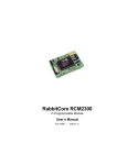
RabbitCore RCM3100
C-Programmable Module
Getting Started Manual
019–0114 •
040515–C
RabbitCore RCM3100 Getting Started Manual
Part Number 019-0114 • 040515–C • Printed in U.S.A.
©2002–2004 Z-World Inc. • All rights reserved.
Z-World reserves the right to make changes and
improvements to its products without providing notice.
Trademarks
Rabbit and Rabbit 3000 are registered trademarks of Rabbit Semiconductor.
RabbitCore is a trademark of Rabbit Semiconductor.
Dynamic C is a registered trademark of Z-World Inc.
Z-World, Inc.
Rabbit Semiconductor
2900 Spafford Street
Davis, California 95616-6800
USA
2932 Spafford Street
Davis, California 95616-6800
USA
Telephone: (530) 757-3737
Fax: (530) 757-3792
Telephone: (530) 757-8400
Fax: (530) 757-8402
www.zworld.com
www.rabbitsemiconductor.com
RabbitCore RCM3100
Table of Contents
Chapter 1. Introduction & Overview
1
1.1 Rabbit 3000 Microprocessor ................................................................................................................ 1
1.2 RCM3100 Series RabbitCore Modules................................................................................................ 2
1.2.1 Physical & Electrical Specifications ........................................................................................... 3
1.3 Development Software......................................................................................................................... 4
1.4 How to Use This Manual ..................................................................................................................... 4
1.4.1 Additional Product Information .................................................................................................. 4
1.4.2 Additional Reference Information .............................................................................................. 4
1.4.3 Using Online Documentation ...................................................................................................... 5
Chapter 2. Hardware Setup
7
2.1 Development Kit Contents................................................................................................................... 7
2.2 Prototyping Board ................................................................................................................................ 8
2.2.1 Prototyping Board Features ......................................................................................................... 9
2.3 Development Hardware Connections ................................................................................................ 11
2.3.1 Attach Module to Prototyping Board ........................................................................................ 11
2.3.2 Connect Programming Cable .................................................................................................... 12
2.3.3 Connect Power .......................................................................................................................... 13
2.4 Run a Sample Program ...................................................................................................................... 14
2.5 Where Do I Go From Here?............................................................................................................... 14
2.5.1 Technical Support ..................................................................................................................... 14
Chapter 3. Software Installation & Overview
15
3.1 An Overview of Dynamic C .............................................................................................................. 15
3.1.1 Hardware Requirements ............................................................................................................ 16
3.2 Installing Dynamic C ......................................................................................................................... 17
3.2.1 Program & Documentation File Location ................................................................................. 17
3.2.2 Installation Type ........................................................................................................................ 18
3.2.3 Select COM Port ....................................................................................................................... 19
3.2.4 Desktop Icons ............................................................................................................................ 19
3.3 Starting Dynamic C............................................................................................................................ 20
3.3.1 Communication Error Messages ............................................................................................... 20
3.4 Sample Programs ............................................................................................................................... 21
Getting Started
Notice to Users
23
Index
25
Schematics
27
RabbitCore RCM3100
1. INTRODUCTION & OVERVIEW
The Rabbit 3000 is a modern 8-bit microprocessor that is the central element of a complete and fully supported embedded design
system that includes development tools, software libraries, core
modules, sample designs, a parts store, and readily available
expert, human support.
This Development Kit has the essentials that you need to design
your own microprocessor-based system, and includes a complete
Dynamic C software development system. This Development Kit
contains a powerful RabbitCore module (the RCM3110) and Prototyping Board that will allow you to evaluate the Rabbit 3000
and to prototype circuits that interface to a Rabbit 3000 microprocessor. You will also be able to write and test software for the
RCM3100 series RabbitCore modules.
1.1 Rabbit 3000 Microprocessor
The Rabbit 3000 microprocessor shares its instruction set and conceptual design with the
successful Rabbit 2000. The instruction set is based on the Z80/Z180, but has been
adapted to be C-friendly and to allow a megabyte of code space. Rabbit processors are fast
with compact code.
The Rabbit 3000 has an extensive array of on-chip peripherals including 6 serial ports, 56
parallel I/O pins, motion control interfaces, a time/date clock, glueless memory and I/O
interfacing, a slave interface, and in-circuit programming. Low-EMI features such as a
clock spectrum spreader eliminate schedule-wrecking EMI problems.
Software development support is based on Z-World’s Dynamic C, and includes extensive
libraries for chip peripherals and more.
Refer to the Rabbit 3000 Microprocessor User’s Manual for complete information on the
Rabbit 3000 microprocessor and complete specifications.
Getting Started
1
1.2 RCM3100 Series RabbitCore Modules
The RCM3100 series RabbitCore modules are designed for use on a customer-supplied
motherboard that supplies power and interfaces to real-world I/O devices. Their two 34pin connection headers provide 54 digital parallel user I/O lines, shared with five serial
ports, along with control lines. A sixth serial port and one additional I/O line are available
on the programming header.
A fully enabled slave port permits glueless master-slave interface with another Rabbitbased system. The slave port may also be used with non-Rabbit systems, although additional logic may be required.
The RCM3100 series is equipped with 256K–512K flash memory and 128K–512K static
RAM.
There are two production models in the RCM3100 series. If the standard models do not
serve your needs, other variations can be specified and ordered in production quantities.
Contact your Z-World or Rabbit Semiconductor sales representative for details.
Table 1 below highlights the differences between the two models in the RCM3100 family.
Table 1. RCM3100 Versions
Feature
Microprocessor
Flash Memory
Static RAM
Serial Ports
RCM3100
RCM3110
Rabbit 3000 running at 29.4 MHz
2 × 256K
256K
512K
128K
6 shared high-speed, CMOS-compatible ports:
6 are configurable as asynchronous serial ports;
4 are configurable as clocked serial ports (SPI);
2 are configurable as SDLC/HDLC serial ports;
1 asynchronous clocked serial port is dedicated
for programming
NOTE: The RCM3110 is the RabbitCore module supplied with the Development Kit.
In addition, there is an RCM3000 series of RabbitCore modules that includes Ethernet connectivity.
The RabbitCore modules can be programed locally, remotely, or via a network using
appropriate interface hardware.
2
RabbitCore RCM3100
1.2.1 Physical & Electrical Specifications
Table 2 lists the basic specifications for the RCM3100.
Table 2. RCM3100 Specifications
Specification
Data
Power Supply
3.15 – 3.45 V DC (75 mA at 29.4 MHz clock speed)
Size
1.65" × 1.85" × 0.55" (42 mm × 47 mm × 14 mm)
Environmental
–40°C to 85°C, 5–95% humidity, noncondensing
NOTE: For complete product specifications, see Appendix A in the RabbitCore
RCM3100 User’s Manual.
The RCM3100 modules have two 34-pin headers to which cables can be connected, or
which can be plugged into matching sockets on a production device. The pinouts for these
connectors are shown in Figure 1 below.
J1
GND
PA7
PA5
PA3
PA1
PF3
PF1
PC0
PC2
PC4
PC6
PG0
PG2
PD4
PD2
PD6
PD0
J2
STATUS
PA6
PA4
PA2
PA0
PF2
PF0
PC1
PC3
PC5
PC7
PG1
PG3
PD5
PD3
PD7
PD1
/RES
PB2
PB4
PB6
PF4
PF6
PE7
PE5
PE3
PE0
PG6
PG4
/IORD
SMOD1
VRAM
+3.3 V
n.c.
PB0
PB3
PB5
PB7
PF5
PF7
PE6
PE4
PE1
PG7
PG5
/IOWR
SMOD0
/RESET_IN
VBAT_EXT
GND
GND
n.c. = not connected
Note: These pinouts are as seen on
the Bottom Side of the module.
Figure 1. RCM3100 Connector Pinout
Getting Started
3
1.3 Development Software
The RCM3100 module uses the Dynamic C development environment for rapid creation
and debugging of runtime applications. Dynamic C provides a complete development
environment with integrated editor, compiler and debugger. It interfaces directly with the
target system, eliminating the need for complex and unreliable in-circuit emulators.
Dynamic C must be installed on a Windows workstation with at least one free serial USB
or COM port for communication with the target system.
NOTE: An RS-232/USB converter is required if you intend to use a USB port on your
computer. Z-World and Rabbit Semiconductor offer a suitable converter—more information is available at www.rabbitsemiconductor.com, or you may telephone your
Z-World/Rabbit Semiconductor sales representative or authorized distributor.
See Chapter 3., “Software Installation & Overview,” for complete information on installing Dynamic C.
NOTE: The RCM3100 module requires Dynamic C v7.25 or later for development. A
compatible version is included on the Development Kit CD-ROM.
1.4 How to Use This Manual
This Getting Started manual is intended to give users a quick but solid start with the
RCM3100 series modules. It does not contain detailed information on the module hardware capabilities or the Dynamic C development environment. Most users will want more
detailed information on some or all of these topics in order to put the RCM3100 module to
effective use.
1.4.1 Additional Product Information
Detailed information about the RCM3100 will be found in the RabbitCore RCM3100
User’s Manual, provided on the accompanying CD-ROM in both HTML and Adobe PDF
format.
Some advanced users may choose to skip the rest of this introductory manual and proceed
directly with the detailed hardware and software information in the User’s Manual.
TIP: We recommend that anyone not thoroughly familiar with Z-World controllers at
least read through the rest of this manual to gain the necessary familiarity to make use
of the more advanced information.
1.4.2 Additional Reference Information
In addition to the product-specific information contained in the RabbitCore RCM3100
User’s Manual, several higher level reference manuals are provided in HTML and PDF
form on the accompanying CD-ROM. Advanced users will find these references valuable
in developing systems based on the RCM3100 module:
• Dynamic C User’s Manual
• Dynamic C Function Reference Manual
• Rabbit 3000 Microprocessor User’s Manual
4
RabbitCore RCM3100
1.4.3 Using Online Documentation
We provide the bulk of our user and reference documentation in two electronic formats,
HTML and Adobe PDF. We do this for several reasons.
We believe that providing all users with our complete library of product and reference
manuals is a useful convenience. However, printed manuals are expensive to print, stock
and ship. Rather than include and charge for manuals that every user may not want, or provide only product-specific manuals, we choose to provide our complete documentation
and reference library in electronic form with every development kit and with our Dynamic
C development environment.
NOTE: The most current version of Adobe Acrobat Reader can always be downloaded
from Adobe’s web site at http://www.adobe.com.
We recommend that you use version 4.0 or later.
Providing this documentation in electronic form saves an enormous amount of paper by
not printing copies of manuals that users don’t need.
Finding Online Documents
The online documentation is installed along with Dynamic C, and an icon for the documentation menu is placed on the workstation’s desktop. Double-click this icon to reach the
menu. If the icon is missing, create a new desktop icon that points to default.htm in the
docs folder, found in the Dynamic C installation folder.
The latest versions of all documents are always available for free, unregistered download
from our web sites as well.
Printing Electronic Manuals
We recognize that many users prefer printed manuals for some uses. Users can easily print
all or parts of those manuals provided in electronic form. The following guidelines may be
helpful:
• Print from the Adobe PDF versions of the files, not the HTML versions.
• If your printer supports duplex printing, print pages double-sided.
• If you do not have a suitable printer or do not want to print the manual yourself, most
retail copy shops (e.g. Kinkos, AlphaGraphics, etc.) will print the manual from the PDF
file and bind it for a reasonable charge—about what we would have to charge for a
printed and bound manual.
Getting Started
5
6
RabbitCore RCM3100
2. HARDWARE SETUP
This chapter describes the RCM3100 hardware in more detail, and
explains how to set up and use the accompanying Prototyping Board.
NOTE: This chapter (and this manual) assume that you have the RCM3100 Development
Kit. If you purchased an RCM3100 module by itself, you will have to adapt the information in this chapter and elsewhere to your test and development setup.
2.1 Development Kit Contents
The RCM3100 Development Kit contains the following items:
• RCM3110 module, 256K flash memory, and 128K SRAM.
• RCM3000/RCM3100 Prototyping Board.
• AC adapter, 9 V DC, 1 A. (Included only with Development Kits sold for the North
American market. A header plug leading to bare leads is provided to allow overseas
users to connect a power supply compatible with their local mains power.)
• 10-pin header to DE9 programming cable with integrated level-matching circuitry.
• Dynamic C CD-ROM, with complete product documentation on disk.
• This Getting Started manual.
• A bag of accessory parts for use on the Prototyping Board.
• Registration card.
Getting Started
7
2.2 Prototyping Board
The Prototyping Board included in the Development Kit makes it easy to connect an
RCM3100 series module to a power supply and a PC workstation for development. It also
provides some basic I/O peripherals (switches and LEDs), as well as a prototyping area for
more advanced hardware development.
For the most basic level of evaluation and development, the Prototyping Board can be
used without modification.
As you progress to more sophisticated experimentation and hardware development, modifications and additions can be made to the board without modifying or damaging the
RCM3100 module itself.
The Prototyping Board is shown below in Figure 2, with its main features identified.
MOTOR/ENCODER
J6
PE7
PF0
PF1
PF7
PF6
PF2
PF3
PF5
PF4
PA0
PA1
PB7
PB6
PA2
PA3
PB5
PB4
PA4
PA5
PB3
PB2
PA6
PA7
PE4
/RES
RN2
J1
UX10
R4
R3
+3.3V
Through-Hole
Prototyping Area
RC24
SMT Prototyping
Area
R8
R12
R6
RC14
RC22
RC16
R7
UX3
RC12
RC21
R9
R11
RC10
R13
R21
+3.3V
RC23
UX9
RC17
RC13
+5V
BT1
UX11
RCM3000
RABBITCORE
RC20
R10
C3
R5
R2
SLAVE
RCM2
RC19
+5V
J15
MASTER
RC15
C2
RCM3000/RCM3100
Master Module
Connectors
J14
GND
C1
Battery
RCM3000 RABBITCORE
RCM1
J3
R1
+DC
U5
RC1
PB0
GND
C12
GND
PE6
2.5 MM JACK
D2
U4
RC2
RC11
GND
PC0
C11 C10
PC1
GND
PE5
+5V
PC2
PE4
+5V
PC4
PC3
J11
D1
C13
R20
R17
RC18
PD5
PC5
PE3
CURRENT
MEASUREMENT
OPTION
PG0
PD4
PE0
PE1
C17
JP1
PG1
PG6
PG7
DS3
PG4
PG5
+3.3V
POWER
/IOWR
C15
PG2
POWER
PD4
PG3
L1
J9
PD5
/IORD
RN5
RN4
IRDA
Transceiver
SM1
SM0
GND
+DC
PD2
GND
PD6
PD3
GND
PD0
PD7
VRAM
+5V
PD1
+3.3V
RN3
NC
GND
Power
Input
Power
LED
+3.3V
RN1
GND
VBAT
EXT
/RES
IN
Voltage
Regulators
CurrentMeasurement
Header
RCM3000/RCM3100
Slave Module
Connectors
Slave Module
Extension Headers
UX2
GND
GND
GND
PE1
PE3
PC3
PC2
PE4
PE5
PC1
PC0
PE6
PE7
PF0
PF1
PF7
PF6
PF2
PF3
PF5
PF4
PA0
PA1
PB7
PB6
PA2
PA3
PB5
PB4
PA4
PA5
PB3
PB2
PA6
PA7
PB0
/RES
PE4
GND
R14
+5V
UX4
+5 V, 3.3 V, and
GND Buses
+5V
C9
U6
C16
DISPLAY BOARD
RC25
RC4
RC5
C14
RC27
U3
U3
RC28
RC29
RC26
UX5
RC9
UX7
U1
C5
C8
J12
RESET
C6
J5
TxB RxB
Reset
Switch
GND
RCM3000 PROTOTYPING BOARD
J13
S2
RxC TxC
J4
Master Module
Extension Headers
BD6
PC4
/RES
LCD
PC5
+5V
PE0
RC7
+5V
PG7
RC6
SMT Prototyping
Area
BPE3
PD5
R16
PG0
PD4
TP1
PG2
PG1
PG6
R15
PD4
PG3
PG4
C4
PD5
/IORD
PG5
BD4
SM1
SM0
/IOWR
BD7
+5V
BD5
PD2
BD2
PD3
+5V
J8
BD0
VRAM
+3.3V
+3.3V
BA1
VBAT
EXT
/RES
IN
+3.3V
+3.3V
BA3
PD6
BD3
PD7
GND
+3.3V
GND
GND
BD1
PD0
GND
PD1
BA0
NC
BA2
GND
GND
S3
PG6
RS-232
J10
RS-232
Signal
Header
DS1
UX13
PG7
C7
DS2
User
Switches
DISPLAY BOARD
User
LEDs
J7
DISPLAY BOARD
LCD/Keypad
Module
Connections
Figure 2. RCM3000/RCM3100 Prototyping Board
8
RabbitCore RCM3100
2.2.1 Prototyping Board Features
• Power Connection—A power-supply jack and a 3-pin header are provided for connection to the power supply. Note that the 3-pin header is symmetrical, with both outer
pins connected to ground and the center pin connected to the raw V+ input. The cable
of the AC adapter provided with the North American version of the Development Kit
ends in a plug that connects to the power-supply jack. The header plug leading to bare
leads provided for overseas customers can be connected to the 3-pin header in either
orientation.
Users providing their own power supply should ensure that it delivers 8–24 V DC at
1 A. The voltage regulators will get warm while in use.
• Regulated Power Supply—The raw DC voltage provided at the POWER IN jack is
routed to a 5 V switching voltage regulator, then to a separate 3.3 V linear regulator.
The regulators provide stable power to the RCM3100 series module and the Prototyping Board.
• Power LED—The power LED lights whenever power is connected to the Prototyping
Board.
• Reset Switch—A momentary-contact, normally open switch is connected directly to the
RCM3100’s /RESET_IN pin. Pressing the switch forces a hardware reset of the system.
• I/O Switches and LEDs—Two momentary-contact, normally open switches are connected to the PG0 and PG1 pins of the master RCM3100 module and may be read as
inputs by sample applications.
Two LEDs are connected to the PG6 and PG7 pins of the master module, and may be
driven as output indicators by sample applications.
• Prototyping Area—A generous prototyping area has been provided for the installation
of through-hole components. +3.3 V, +5 V, and Ground buses run around the edge of
this area. Several areas for surface-mount devices are also available. (Note that there
are SMT device pads on both top and bottom of the Prototyping Board.) Each SMT pad
is connected to a hole designed to accept a 30 AWG solid wire.
• Slave Module Connectors—A second set of connectors is pre-wired to permit installation of a second, slave RCM3100 series or RCM3100 series module. This capability
is reserved for future use, although the schematics in this manual contain all of the
details an experienced developer will need to implement a master-slave system.
• Module Extension Headers—The complete pin sets of both the MASTER and
SLAVE RabbitCore modules are duplicated at these two sets of headers. Developers
can solder wires directly into the appropriate holes, or, for more flexible development,
26-pin header strips can be soldered into place. See Figure 1 for the header pinouts.
• RS-232—Two 3-wire or one 5-wire RS-232 serial port are available on the Prototyping
Board. Refer to the Prototyping Board schematic (090-0137) for additional details.
A 10-pin 0.1-inch spacing header strip is installed at J5 to permit connection of a ribbon
cable leading to a standard DE-9 serial connector.
Getting Started
9
• Current Measurement Option—Jumpers across pins 1–2 and 5–6 on header JP1 can
be removed and replaced with an ammeter across the pins to measure the current drawn
from the +5 V or the +3.3 V supplies, respectively.
• Motor Encoder—A motor/encoder header is provided at header J6 for future use.
• LCD/Keypad Module—Z-World’s LCD/keypad module (Z-World part number
101-0465) may be plugged in directly to headers J7, J8, and J10.
10
RabbitCore RCM3100
2.3 Development Hardware Connections
There are four steps to connecting the Prototyping Board for use with Dynamic C and the
sample programs:
1. Attach the RCM3100 series module to the Prototyping Board.
2. Connect the programming cable between the RCM3100 module and the workstation PC.
3. Connect the power supply to the Prototyping Board.
2.3.1 Attach Module to Prototyping Board
Turn the RCM3100 series module so that the mounting holes on the RCM3100 and on the
Prototyping Board line up, as shown in Figure 3 below. Align the module headers J1 and
J2 into sockets J12 and J13 on the Prototyping Board.
MOTOR/ENCODER
J6
PA5
C11 C10
MASTER
R19
D1
+5V
R17
R18
R12
J3
RC2
U2
C46
UX2
R5
R4
C54
C53
C3
+3.3V
PD3
PD2
SM1
PD5
PD4
/IORD
PG3
PG2
/IOWR
PG4
PG1
PG0
PG5
PG6
PD4
PD5
PG7
PE0
PC5
PC4
PE1
PE3
PC3
PC2
PE4
PE5
PC1
PC0
PE6
PE7
PF0
PF1
PF7
PF6
PF2
PF3
PF5
PF4
PA0
PA1
PB7
PB6
PA2
PA3
PB5
PB4
PA4
PA5
PB3
PB2
PA6
PA7
PB0
/RES
PE4
GND
+3.3V
RC6
RC7
C9
J13
J12
+5V
J8
+5V
UX4
+5V
R15
C44
VRAM
SM0
TP1
+3.3V
+5V
VBAT
EXT
/RES
IN
GND
GND
+3.3V
PD6
U6
C16
DISPLAY BOARD
RC25
RC4
RC5
C14
RC27
U3
U3
RC28
RC29
RC26
UX5
R14
RC9
UX7
U1
C5
C8
J12
RESET
C4
Y1
PD7
C43
+3.3V
PD0
C58
PD1
GND
GND
RP1
C4
NC
R16
C14
C22
C18
C24
U5
GND
C57
RP2
C39
R14 R26
R9
RP4
RC21
R11
RC10
R13
JP1
RP3
R12
R7
JP2
GND
R6
JP3
GND
UX3
RC12
RC11
RC22
RC16
RC13
R21
R8
RC14
RC17
RC24
RC23
R10
JP4
R2
R11
R20 R23
R21
U7
UX9
C13
R30 U6
C23
R24
C25
RC20
C3
R5
UX11
RCM3000
RABBITCORE
C17
C59 C42 C52
C26
Y2
RC19
R4
C41
R3
RCM2
RC1
RC15
+3.3V
J15
SLAVE
UX10
GND
C1
R1
C45
J14
PA7
J3
R16 C47
PE4
C55
PA6
/RES
C2
RCM3100
PB2
RN2
J1
C56
PB0
+3.3V
BT1
RCM3000 RABBITCORE
RCM1
Q1
PB3
+DC
GND
PA4
GND
GND
PB4
BD6
PB5
Battery
BD4
PA3
BD2
PA1
PA2
BD7
PF3
PA0
PB6
BD5
PF1
PF2
PF4
BD3
PF0
PF6
PF5
BD0
PE7
PF7
PB7
+5V
BA1
PE6
Line up mounting
holes.
+5V
BA3
PC0
BD1
PC1
U5
GND
PE5
C12
GND
PE4
2.5 MM JACK
D2
U4
BA0
PC2
GND
PC3
BA2
PE3
/RES
LCD
PC4
PE1
+5V
PD5
PC5
+5V
PG0
PD4
PE0
BPE3
PG1
PG6
PG7
GND
PG4
PG5
R17
+5V
/IOWR
J11
D1
C13
R20
RC18
PG2
C17
JP1
PG3
CURRENT
MEASUREMENT
OPTION
/IORD
DS3
SM0
+3.3V
POWER
PD4
C15
PD2
PD5
L1
POWER
PD3
SM1
RN5
J9
VRAM
VBAT
EXT
/RES
IN
GND
+DC
PD6
GND
PD7
GND
PD0
+3.3V
RN4
PD1
GND
RN3
NC
+5V
+3.3V
RN1
GND
C6
RxC TxC
J5
J4
TxB RxB
GND
RCM3000 PROTOTYPING BOARD
J13
S2
S3
PG6
RS-232
J10
DS1
UX13
PG7
C7
DS2
DISPLAY BOARD
J7
DISPLAY BOARD
Figure 3. Installing the RCM3100 Series Module on the Prototyping Board
Although you can install a single module into either the MASTER or the SLAVE position
on the Prototyping Board, all the Prototyping Board features (switches, LEDs, serial port
drivers, etc.) are connected to the MASTER position. We recommend you install the
RCM3100 module in the MASTER position unless you plan to use it as a slave with
another RCM3000 or RCM3100 series board.
NOTE: It is important that you line up the pins on headers J1 and J2 of the RCM3100
series module exactly with the corresponding pins of headers J12 and J13 on the Prototyping Board. The header pins may become bent or damaged if the pin alignment is offset, and the module will not work. Permanent electrical damage to the module may also
result if a misaligned module is powered up.
Press the module’s pins firmly into the Prototyping Board headers.
Getting Started
11
2.3.2 Connect Programming Cable
The programming cable connects the RabbitCore module to the PC running Dynamic C to
download programs and to monitor the RabbitCore module for debugging.
Connect the 10-pin connector of the programming cable labeled PROG to header J1 on
the RCM3100 series module as shown in Figure 4. Be sure to orient the marked (usually
red) edge of the cable towards pin 1 of the connector. (Do not use the DIAG connector,
which is used for a normal serial connection.)
NOTE: Be sure to use the programming cable supplied with this Development Kit—the
programming cable has color shrink wrap around the RS-232 converter section located in
the middle of the cable. Programming cables with clear shrink wrap from other Z-World
or Rabbit Semiconductor kits were not designed to work with RCM3100 series modules.
MOTOR/ENCODER
J6
C11 C10
MASTER
J3
RC15
RC20
R8
R10
R12
R6
RC14
RC22
RC17
RC16
PB4
PA4
PA5
PB3
PB2
PA6
PA7
PB0
/RES
PE4
GND
C14
R12
C39
J12
U6
C9
RESET
C5
J5
J4
TxB RxB
GND
J13
S2
S3
DS1
BD2
BD4
BD6
BD5
BD7
RC25
RC4
RC5
C14
RC27
RC28
RC29
RC26
Colored
shrink wrap
UX13
RCM3000 PROTOTYPING BOARD
PG6
C7
RS-232
DISPLAY BOARD
To
PC COM port
UX7
C8
C6
RxC TxC
C16
U3
UX5
R14
+5V
UX4
+5V
R15
RC7
BD3
D1
U5
RC6
+5V
J8
BD0
C24
R20 R23
R21
C59 C42 C52
C45
+3.3V
+3.3V
+5V
RP1
PB5
GND
RC9
U1
C4
PA3
RP4
PA1
PA2
RP3
PF3
PA0
PB6
C44
PF1
PF2
PF4
Y1
PF0
PF6
PF5
+3.3V
C43
PE7
PF7
PB7
C53
PE6
C54
PC0
C3
PC2
PC1
R4
PC4
PC3
PE5
R5
PC5
PE3
PE4
C4
PE0
PE1
U2
PG7
GND
GND
+3.3V
U3
C46
PD5
PG2
RP2
PG0
PD4
PD4
R14 R26
PG1
PG6
PD2
PD5
U7
GND
PG4
PG5
PD6
PD3
C57
/IOWR
PD7
PG3
R30 U6
/IORD
JP1
SM1
JP2
VRAM
JP3
+3.3V
SM0
JP4
GND
VBAT
EXT
/RES
IN
UX2
GND
C26
PD0
C23
R24
C25
PD1
Y2
NC
C41
GND
BA1
R9
R11
RC2
RC11
GND
RC21
RC10
R13
R21
R7
UX3
RC12
BA3
RC13
GND
+5V
UX9
C3
R5
R2
RC24
RC23
C22
C18
R3
UX11
RCM3000
RABBITCORE
RCM2
RC19
RC1
C2
R4
R17
R18
C1
R1
C56
RN2
J1
J15
SLAVE
UX10
BT1
RCM3000 RABBITCORE
RCM1
J14
BD1
GND
GND
PE4
GND
/RES
BA0
PA7
PB0
GND
PA5
PA6
BA2
PA3
PA4
PB2
/RES
LCD
PA2
PB4
PB3
+5V
+3.3V
+5V
PB6
PB5
+5V
+3.3V
+5V
PB7
Battery
BPE3
PA1
+DC
GND
PF3
PA0
GND
+5V
PF1
PF2
PF4
R16
PF0
PF6
PF5
DIAG
PE7
PF7
R16 C47
PE6
TP1
PC0
J3
PC1
RC18
PE5
2.5 MM JACK
C12
U5
R19
PE4
J11
D2
U4
R11
PC2
PROG
PC3
C58
PE3
C13
PC4
PE1
C55
PD5
PC5
C17
PG0
PD4
PE0
Q1
PG2
PG1
PG6
JP1
PG3
PG4
PG7
CURRENT
MEASUREMENT
OPTION
/IORD
PG5
C17
D1
C13
R20
R17
RN4
SM0
/IOWR
L1
DS3
PD4
+3.3V
POWER
PD2
PD5
C15
PD3
SM1
RN5
POWER
VRAM
VBAT
EXT
/RES
IN
GND
J9
PD6
+DC
PD7
GND
PD0
+3.3V
GND
PD1
GND
RN3
NC
+5V
+3.3V
RN1
GND
PG7
Colored edge
DS2
J7
DISPLAY BOARD
DISPLAY BOARD
J3
PROG
Programming Cable
Figure 4. Connect Programming Cable to RCM3100
Connect the other end of the programming cable to a COM port on your PC.
NOTE: Some PCs now come equipped only with a USB port. It may be possible to use an
RS-232/USB converter with the programming cable supplied with the RCM3100 series
Development Kit. Contact Technical Support (see Section 2.5.1) for further assistance.
12
RabbitCore RCM3100
2.3.3 Connect Power
When all other connections have been made, you can connect power to the
RCM3000/RCM3100 Prototyping Board.
Connect the wall transformer to jack J11 on the Prototyping Board as shown in Figure 5
below.
3-pin
power connector
MOTOR/ENCODER
J6
C11 C10
J14
PA7
SLAVE
UX10
GND
MASTER
J3
RC15
RC20
UX9
R8
R10
C3
R5
R12
R6
RC14
RC13
RC16
R7
UX3
RC12
RC21
R9
R11
RC10
R13
RC2
RC11
GND
PA3
PA4
PA5
PB3
PB2
PA6
PA7
PB0
/RES
PE4
R12
C14
RESET
R16
U5
TP1
D1
C22
C18
R16 C47
R19
R17
R18
C24
R20 R23
R21
C59 C42 C52
C45
C39
J12
RC7
+5V
R15
C9
U6
C16
DISPLAY BOARD
RC25
RC4
RC5
C14
RC27
U3
RC28
C5
J3
UX7
C8
C6
RxC TxC
GND
J5
J4
TxB RxB
RC26
UX5
R14
RP1
PA1
PA2
PB4
C4
PF3
PA0
PB6
RP4
PF2
PF4
RC6
+5V
UX4
RC29
RP3
PF6
PF5
JP1
PF7
PB7
+5V
+5V
J8
RC9
U1
C44
PF1
C53
PC0
PF0
Y1
PC2
PC1
PE7
+3.3V
+3.3V
+3.3V
U3
C54
PC4
PC3
PE5
PE6
C3
PC5
PE3
PE4
R4
PE0
PE1
R5
PG7
C4
PD5
U2
PD4
GND
GND
+3.3V
C46
PG6
RP2
PG5
R14 R26
PG0
JP2
PG2
PG1
JP3
PD4
PG3
PG4
U7
GND
PD2
PD5
/IORD
C57
PD3
SM1
JP4
VRAM
SM0
/IOWR
R30 U6
PD6
+3.3V
C26
PD7
GND
VBAT
EXT
/RES
IN
C23
R24
C25
PD0
Y2
PD1
C41
NC
PB5
UX2
GND
GND
R11
R21
GND
RC22
RC17
C43
R2
RC24
RC23
C58
R3
UX11
RCM3000
RABBITCORE
RC19
GND
R4
+5V
C2
R1
RCM2
RC1
C1
C13
PE4
+3.3V
C55
PA6
/RES
+3.3V
C17
PB2
RN2
J1
+DC
BT1
C56
PB0
GND
J15
Q1
PB3
Battery
RCM3000 RABBITCORE
RCM1
BD6
PA5
BD4
PA4
BD7
PB4
BD5
PA3
PB5
BD2
PA1
PA2
BD0
PF3
PA0
PB6
BA1
PF1
PF2
PF4
BA3
PF0
PF6
PF5
BD3
PE7
PF7
PB7
+5V
GND
PE6
+5V
GND
PC0
BD1
PC1
U5
GND
PE5
C12
BA0
PE4
2.5 MM JACK
D2
U4
BA2
PC2
/RES
LCD
PC4
PC3
+5V
PD5
PC5
PE3
+5V
PG0
PD4
PE0
PE1
BPE3
PG1
PG6
PG7
GND
PG4
PG5
+5V
/IOWR
J11
RC18
PG2
CURRENT
MEASUREMENT
OPTION
PG3
JP1
/IORD
C17
D1
C13
R20
R17
RN4
SM0
L1
DS3
PD4
+3.3V
POWER
PD2
PD5
C15
PD3
SM1
RN5
POWER
VRAM
GND
J9
PD6
+DC
PD7
GND
PD0
+3.3V
GND
PD1
GND
VBAT
EXT
/RES
IN
RN3
NC
+5V
+3.3V
RN1
GND
GND
RCM3000 PROTOTYPING BOARD
J13
S2
S3
PG6
RS-232
J10
DS1
UX13
PG7
C7
DS2
DISPLAY BOARD
J7
DISPLAY BOARD
Figure 5. Power Supply Connections
Plug in the wall transformer. The power LED on the Prototyping Board should light up.
The RCM3100 and the Prototyping Board are now ready to be used.
NOTE: A RESET button is provided on the Prototyping Board to allow hardware reset
without disconnecting power.
To power down the Prototyping Board, unplug the power connector from J11. You should
disconnect power before making any circuit adjustments in the prototyping area, changing
any connections to the board, or removing the RCM3100 from the Prototyping Board.
2.3.3.1 Overseas Development Kits
Development kits sold outside North America include a header connector that may be
connected to 3-pin header J9 on the Prototyping Board. The connector may be attached
either way as long as it is not offset to one side. The red and black wires from the connector can then be connected to the positive and negative connections on your power supply.
The power supply should deliver 8 V–24 V DC at 1 A.
Getting Started
13
2.4 Run a Sample Program
If you already have Dynamic C installed, you are now ready to test your programming
connections by running a sample program.
Find the file PONG.C, which is in the Dynamic C SAMPLES folder. To run the program,
open it with the File menu (if it is not still open), compile it using the Compile menu, and
then run it by selecting Run in the Run menu. The STDIO window will open and will display a small square bouncing around in a box.
This program shows that the CPU is working.
2.5 Where Do I Go From Here?
We recommend that you proceed to the next chapter and install Dynamic C (if you do not
already have it installed), then run the PONG.C sample program to verify that the
RCM3100 module and the Prototyping Board are set up and functioning correctly.
If everything appears to be working, we recommend the following sequence of action:
1. Run all of the sample programs described in Section 3.4 to get a basic familiarity with
Dynamic C and the RCM3100 module’s capabilities.
2. For further development, refer to the RabbitCore RCM3100 User’s Manual for details
of the module’s hardware and software components.
A documentation icon should have been installed on your workstation’s desktop; click
on it to reach the documentation menu. You can create a new desktop icon that points to
default.htm in the docs folder in the Dynamic C installation folder.
3. For advanced development topics, refer to the Dynamic C User’s Manual, also in the
online documentation set.
2.5.1 Technical Support
NOTE: If you purchased your RCM3100 series module through a distributor or through a
Z-World or Rabbit Semiconductor partner, contact the distributor or partner first for technical support.
If there are any problems at this point:
• Check the Z-World/Rabbit Semiconductor Technical Bulletin Board at
www.zworld.com/support/.
• Use the Technical Support e-mail form at www.zworld.com/support/.
14
RabbitCore RCM3100
3. SOFTWARE INSTALLATION & OVERVIEW
To develop and debug programs for the RCM3100 (and for all
other Z-World and Rabbit Semiconductor hardware), you must
install and use Dynamic C. This chapter takes you through the
installation of Dynamic C, and then provides a tour of its major
features with respect to the RCM3100.
3.1 An Overview of Dynamic C
Dynamic C integrates the following development functions into one program:
• Editing
• Compiling
• Linking
• Loading
• In-Circuit Debugging
In fact, compiling, linking and loading are one function. Dynamic C does not use an InCircuit Emulator; programs being developed are downloaded to and executed from the
“target” system via an enhanced serial-port connection. Program development and debugging take place seamlessly across this connection, greatly speeding system development.
Other features of Dynamic C include:
• Dynamic C has an easy-to-use built-in text editor. Programs can be executed and
debugged interactively at the source-code or machine-code level. Pull-down menus and
keyboard shortcuts for most commands make Dynamic C easy to use.
• Dynamic C also supports assembly language programming. It is not necessary to leave
C or the development system to write assembly language code. C and assembly language may be mixed together.
• Debugging under Dynamic C includes the ability to use printf commands, watch
expressions, breakpoints and other advanced debugging features. Watch expressions
can be used to compute C expressions involving the target’s program variables or
functions. Watch expressions can be evaluated while stopped at a breakpoint, singlestepping, or while the target is running its program.
Getting Started
15
• Dynamic C provides extensions to the C language (such as shared and protected variables, costatements and cofunctions) that support real-world embedded system development. Dynamic C supports cooperative and preemptive multi-tasking.
• Dynamic C comes with many function libraries, all in source code. These libraries support real-time programming, machine level I/O, and provide standard string and math
functions.
• Dynamic C compiles directly to memory. Functions and libraries are compiled and
linked and downloaded on-the-fly. On a fast PC, Dynamic C can load 30,000 bytes of
code in 5 seconds at a baud rate of 115,200 bps.
3.1
Hardware Requirements
To install and run Dynamic C, your system must be running one of the following operating
systems:
• Windows 95
• Windows 98
• Windows NT
• Windows Me
• Windows 2000
• Windows XP
3.1.1 Hardware Requirements
The PC on which you install Dynamic C for development of RCM3100-based systems
should have the following hardware:
• A Pentium or later microprocessor
• 32 MB of RAM
• At least one free COM (serial) port for communication with the target systems
• A CD-ROM drive (for software installation)
16
RabbitCore RCM3100
3.2 Installing Dynamic C
Insert the Dynamic C CD-ROM in the drive on your PC. If autorun is enabled, the CD
installation will begin automatically.
If autorun is disabled or the installation otherwise does not start, use the Windows
Start | Run menu or Windows Disk Explorer to launch SETUP.EXE from the root folder
of the CD-ROM.
The installation program will guide you through the installation process. Most steps of the
process are self-explanatory and not covered in this section. Selected steps that may be
confusing to some users are outlined below. (Some of the installation utility screens may
vary slightly from those shown.)
3.2.1 Program & Documentation File Location
Dynamic C’s application, library and documentation files can be installed in any convenient location on your workstation’s hard drives.
The default location, as shown in the example above, is in a folder named for the version
of Dynamic C, placed in the root folder of the C: drive. If this location is not suitable, enter
a different root path before clicking Next >. Files are placed in the specified folder, so do
not set this location to a drive’s root directory.
Getting Started
17
3.2.2 Installation Type
Dynamic C has two components that can be installed together or separately. One component is Dynamic C itself, with the development environment, support files and libraries.
The other component is the documentation library in HTML and PDF formats, which may
be left uninstalled to save hard drive space or installed elsewhere (on a separate or network drive, for example).
The installation type is selected in the installation menu shown above. The options are:
• Typical Installation — Both Dynamic C and the documentation library will be
installed in the specified folder (default).
• Compact Installation — Only Dynamic C will be installed.
• Custom Installation — You will be allowed to choose which components are
installed. This choice is useful to install or reinstall just the documentation.
18
RabbitCore RCM3100
3.2.3 Select COM Port
Dynamic C uses a COM (serial) port to communicate with the target development system.
The installation allows you to choose the COM port that will be used.
The default selection, as shown in the example above, is COM1. You may select any available port for Dynamic C’s use. If you are not certain which port is available, select COM1.
This selection can be changed later within Dynamic C.
NOTE: The installation utility does not check the selected COM port in any way. Specifying a port in use by another device (mouse, modem, etc.) may lead to a message such
as "could not open serial port" when Dynamic C is started.
3.2.4 Desktop Icons
Once your installation is complete, you will have up to three icons on your PC desktop, as
shown below.
One icon is for Dynamic C, one opens the documentation menu, and the third is for the
Rabbit Field Utility, a tool used to download precompiled software to a target system.
Getting Started
19
3.3 Starting Dynamic C
Once the RCM3100 is set up and connected as described in Chapter 2 and Dynamic C has
been installed, start Dynamic C by double-clicking on the Dynamic C icon. Dynamic C
should start, then look for the target system on the COM port you specified during installation (by default, COM1). Once detected, Dynamic C should go through a sequence of
steps to cold-boot the module and compile the BIOS.
If you receive the message beginning "BIOS successfully compiled" you are
ready to continue with the sample programs.
3.3.1 Communication Error Messages
If you receive the message "No Rabbit Processor Detected," the programming
cable may be connected to a different COM port, a connection may be faulty, or the target
system may not be powered up. First, check to see that the power LED on the Prototyping
Board is lit and that the jumper across pins 5–6 of header JP1 on the Prototyping Board is
installed. If the LED is lit, check both ends of the programming cable to ensure that it is
firmly plugged into the PC and the RCM3100 series module’s programming port. If you
are using the Prototyping Board, ensure that the module is firmly and correctly installed in
its connectors.
If there are no faults with the hardware, select a different COM port within Dynamic C.
From the Options menu, select Communications. The dialog shown should appear.
Select another COM port from the list, then click OK. Press <Ctrl-Y> to force Dynamic C to recompile the BIOS. If Dynamic C still reports it is unable to locate the target system, repeat the above
steps until you locate the active COM port.
If Dynamic C appears to compile the BIOS successfully, but you then receive a communication error message, it is possible that your PC cannot handle the 115,200 bps baud rate.
Try changing the baud rate to 57,600 bps as follows.
• Locate the Serial Options dialog in the Dynamic C Options > Communications
menu. Change the baud rate to 57,600 bps.
20
RabbitCore RCM3100
3.4 Sample Programs
To help familiarize you with the RCM3100 modules, Dynamic C includes several sample
programs. Loading, executing and studying these programs will give you a solid hands-on
overview of the RabbitCore’s capabilities, as well as a quick start with Dynamic C as an
application development tool.
NOTE: The sample programs assume that you have at least an elementary grasp of ANSI
C. If you do not, see the introductory pages of the Dynamic C User’s Manual for a suggested reading list.
Of the many sample programs included with Dynamic C, several are specific to the
RCM3100. These programs will be found in the Samples/RCM3100 folder.
We suggest that you examine the following five of these sample programs in order to get a
tour of some of the capabilities of the RCM3100 modules.
• CONTROLLED.c—This sample program demonstrates the controlling port outputs
from STDIO by toggling LEDs on the Prototyping Board.
• FLASHLED1.c—This assembly program uses costatements to flash LEDs DS1 and
DS2 on the Prototyping Board at different intervals.
• FLASHLED2.c—This program uses cofunction and costatements to flash LEDs DS1
and DS2 on the Prototyping Board at different intervals.
• IR_DEMO.c—This program demonstrates sending packets (Modbus ASCII) back and
forth over an IR link. This demo requires two RCM3000/RCM3100 Prototyping
Boards with an RCM3100 module on each Prototyping Board. Set up the Prototyping
Boards so that their IR transceivers are facing each other. Load the program into one
RCM3100, then operate this RCM3100 in Run mode without a programming cable
attached. Program the other RCM3100 and then observe the results in the STDIO window on your PC with the PROG connector on the programming cable still connected.
• TOGGLESWITCH.c—This program uses costatements to detect switches using the
press-and-release method of debouncing. Corresponding LEDs DS1 and DS2 on the
Prototyping Board turn on or off.
The Samples/RCM3100/Serial folder provides samples to illustrate serial communication with the RCM3100.
Each of these programs is fully commented within the source code. Refer to these comments for the details of how each program works.
To run a program, open it with the File menu (if the sample program is not already open),
compile it using the Compile menu, and then run it by selecting Run in the Run menu.
Once you have loaded and executed these programs and have an understanding of how
Dynamic C and the RCM3100 modules interact, you can move on and try the other sample programs, or begin building your own.
Getting Started
21
22
RabbitCore RCM3100
NOTICE TO USERS
ZWORLD PRODUCTS ARE NOT AUTHORIZED FOR USE AS CRITICAL COMPONENTS IN LIFESUPPORT DEVICES OR SYSTEMS UNLESS A SPECIFIC WRITTEN AGREEMENT REGARDING
SUCH INTENDED USE IS ENTERED INTO BETWEEN THE CUSTOMER AND Z-WORLD PRIOR
TO USE. Life-support devices or systems are devices or systems intended for surgical implantation into the
body or to sustain life, and whose failure to perform, when properly used in accordance with instructions for
use provided in the labeling and user’s manual, can be reasonably expected to result in significant injury.
No complex software or hardware system is perfect. Bugs are always present in a system of any size. In
order to prevent danger to life or property, it is the responsibility of the system designer to incorporate
redundant protective mechanisms appropriate to the risk involved.
All Z-World products are 100 percent functionally tested. Additional testing may include visual quality control inspections or mechanical defects analyzer inspections. Specifications are based on characterization of
tested sample units rather than testing over temperature and voltage of each unit. Z-World products may
qualify components to operate within a range of parameters that is different from the manufacturer’s recommended range. This strategy is believed to be more economical and effective. Additional testing or burn-in
of an individual unit is available by special arrangement.
User’s Manual
23
24
RabbitCore RCM3100
INDEX
A
H
S
additional information
online documentation .......... 5
references ............................ 4
C language ...................... 15, 16
hardware connections ........... 11
install RCM3100 on Prototyping Board ...................... 11
power supply ..................... 13
programming cable ........... 12
hardware reset ....................... 13
D
M
Development Kit ..................... 7
Dynamic C .................. 4, 15, 16
assembly language ............ 15
debugger ............................ 15
debugging .......................... 15
desktop icons ..................... 19
editor ................................. 15
features .............................. 15
handling communication error
messages ....................... 20
hardware requirements ...... 16
installing ................ 17, 18, 19
sample programs ............... 21
starting .............................. 20
watch expressions ............. 15
models
factory versions ................... 2
sample programs ................... 21
getting to know the RCM3100
CONTROLLED.C ........ 21
FLASHLED1.C ............ 21
FLASHLED2.C ............ 21
IR_DEMO.C ................. 21
serial communication .... 21
TOGGLESWITCH.C .... 21
PONG.C ............................ 14
software
sample programs ............... 21
specifications
physical and electrical ......... 3
C
F
features
Prototyping Board ........... 8, 9
RCM3100 ............................ 2
Getting Started
P
pinout
RCM3100 ............................ 3
power supply
connections ....................... 13
programming cable
RCM3100 connections ..... 12
Prototyping Board ................... 8
expansion area ..................... 9
features ............................ 8, 9
mounting RCM3100 ......... 11
T
technical support ................... 14
R
RCM3100
mounting on Prototyping
Board ............................ 11
reset ....................................... 13
25
26
RabbitCore RCM3100
SCHEMATICS
090-0144 RCM3100 Schematic
www.rabbitsemiconductor.com/documentation/schemat/090-0144.pdf
090-0137 RCM3000/RCM3100 Prototyping Board Schematic
www.rabbitsemiconductor.com/documentation/schemat/090-0137.pdf
090-0156 LCD/Keypad Module Schematic
www.rabbitsemiconductor.com/documentation/schemat/090-0156.pdf
090-0128 Programming Cable Schematic
www.rabbitsemiconductor.com/documentation/schemat/090-0128.pdf
The schematics included with the printed manual were the latest revisions available at the
time the manual was last revised. The online versions of the manual contain links to the
latest revised schematic on the Web site. You may also use the URL information provided
above to access the latest schematics directly.
Getting Started
27