1
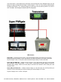
www.westmountainradio.com
Super PWRgate PG40S
Owners Manual
March 28, 2008
Introduction
Thank you for purchasing the Super PWRgate….the high power OR-gate with a built in four-stage battery
charger. It makes a true solid state UPS for the ham shack.
The Super PWRgate eliminates the danger of connecting a power supply directly across a battery. Many
power supplies will be damaged if this is done. The Super PWRgate also avoids introducing hum and RF
interference, caused by most lead acid battery chargers, by using a standard power supply. Furthermore
most lead acid battery chargers are designed for flooded lead acid marine or automotive batteries and are
inappropriate for charging sealed lead acid gel and AGM type batteries. The Super PWRgate will extend
the life span of a sealed lead acid battery compared to using a flooded lead acid charger.
The Super PWRgate transfers 40 amperes at 12 Volts dc continuously in a very safe manner. It connects
a battery and a power supply to a load, while electrically isolating both the battery and the supply from
each other. Whenever the power supply is on, the supply feeds the load. It also charges the battery with
a high-current four-state safe battery charger. Whenever the power supply is off, the battery feeds the
load. If either the power supply or the battery is malfunctioning, neither draws current from the other.
Switching is instantaneous.
A Super PWRgate is very useful in the ham shack, and even more useful in a repeater installation.
Communication equipment will remain operative during ac power blackouts and power supply failure.
Power supplies and batteries can be swapped out while equipment remains on. No glitches.
Additionally, the Super PWRgate and a power supply may be used solely as a permanently installed
battery charger. This also may be configured to run a radio station directly from the battery, as described
by W1ZR in QST, December 2003.
Before installing the Super PWRgate, please read the following instructions.
Choosing a mounting location
Pick a location that is close, or central to, your power supply, battery, and load or 12volt distribution panel.
Radios and many 12 volt devices draw large amounts of current. Remember, all wires have resistance so
they must be kept as short as possible and should have large wire size in order to minimize the voltage
drop.
The Super PWRgate can be installed in any orientation in a cool dry location preferably well ventilated.
Do not tightly enclose the unit because the heat sink will become quite warm under maximum current. It
will rise about 40 degrees Fahrenheit over ambient temperature at 40 A continuous current in free air. Do
not place it in direct sunlight; it will absorb the suns rays and get unnecessarily hot.
The Super PWRgate can be mounted using number 8 hardware in the two mounting holes.
34 Smith Street, Norwalk, Connecticut
06851 phone: 203 853 8080 fax: 203 299 0232
Connecting the power supply
Use a regulated power supply that is between 13.8 volts and 15 volts.
Anderson Powerpoles are used for all Super PWRgate connections. See the section “Powerpole connector
installation tips”.
The power supply wire should be heavy gauge and as short as possible. We suggest #10 wire, 6 feet
long, or preferably 3 feet long. Most power supplies have ¼ inch studs. Note that West Mountain Radio
carries 3 and 6 ft long power supply cables, #10 red and black insulated wire, with 1/4 in ring terminals on
one end and powerpoles on the other.
When connecting, make sure that the RED Powerpole connects to the RED wire and connects to the
PLUS terminal on the supply. Similarly, make sure that the BLACK Powerpole connects to the BLACK
wire and connects to the NEGATIVE terminal on the supply. Check to see that the connections at the
power supply are well tightened.
Plug this wire from the power supply into the Super PWRgate connector marked PS (power supply).
Always confirm that the Powerpoles are plugged together securely, and that the wire is straight at the
connection and is not under strain or bent over.
Connecting the load or power strip
Anderson Powerpoles are used for all Super PWRgate connections. See the section “Powerpole connector
installation tips”.
34 Smith Street, Norwalk, Connecticut
06851 phone: 203 853 8080 fax: 203 299 0232
The load wire should be heavy gauge and as short as possible. If you are connecting directly to a radio or
other device, you will need to install powerpoles on their cords. Modern radios use RED wire for positive,
and BLACK wire for negative (or common or ground). Double-check this if you have non-standard
equipment. Plug this wire into the Super PWRgate terminal marked OUT.
If you are connecting the output to a power strip, such as a RIGrunner, we suggest #10 wire, 6 feet long, or
preferably 3 feet long. At least one end will need Powerpoles installed; the other end can wire directly to
the power strip or use connectors. Note that West Mountain Radio carries 3 and 6 ft long extension
cables, #10 red and black insulated wire, with Powerpoles on both ends.
Plug this wire from the power strip or equipment into the Super PWRgate connector marked OUT (output).
Always confirm that the Powerpoles are plugged together securely, and that the wire is straight at the
connection and is not under strain or bent over.
At this point, check out the system operation with the power supply. Simply turn on the power supply, turn
on the radio or equipment. The radio or equipment should work fine.
Connecting the Battery
Anderson Powerpoles are used for all Super PWRgate connections. See the section “Powerpole connector
installation tips”.
The battery wire should be heavy gauge and as short as possible. We suggest #10 wire, 3 feet long. In
addition, a fuse must be installed in the positive lead directly at the battery terminal. This because any
short in the battery wire, connector, or load could result in fire and battery explosion…a need to be avoided
situation!
Large batteries have side, post, or threaded terminals. Deep cycle, marine, AGM, etc. usually have 3/8
inch and 5/16 inch studs. Therefore, we recommend a short 3 foot #10 wire, Powerpoles on one end, an
in-line fuse (40 A max), and ring terminals for the battery end. West Mountain Radio carries a battery fuse
kit, wire, and Powerpoles.
Batteries
Caution: Handle batteries with knowledge and appropriate care. Batteries can have dangerous
chemicals that can spill out. Batteries can emit extremely explosive hydrogen gas that is
extremely explosive. Batteries, especially automotive and marine flooded lead acid, must be used
in a strong, ventilated enclosure. Sealed lead acid batteries are much safer but must be handled
and cared for correctly.
NEVER make the “last” connection directly to a battery causing a spark that could cause the
battery to explode sending debris and acid in all directions. Batteries can get very hot when
improperly charged or if a cell gets shorted. Batteries will explode during charging or discharging
for a variety of reasons. Think of a battery as if it were a can of gasoline, both may be safe, but
only if handled properly.
Chose a 12 volt battery with an ampere-hour rating according to your power needs. If the batteries are
placed indoors they must be sealed for safety reasons. Again, it is very important to place a fuse at the
positive battery terminal.
We cannot cover all the types of batteries here. But for use in the ham shack we recommend lead-acid
types because they offer the best price to power ratio. Gelled cells and absorbed glass mat (AGM)
batteries are sealed and are very safe. Some of these have a tiny positive pressure vent. We recommend
Gelled cells for use with the Super PWRgate because the battery charging circuit comes configured
34 Smith Street, Norwalk, Connecticut
06851 phone: 203 853 8080 fax: 203 299 0232
properly and matches a 13.8 volt power supply. However, AGM batteries may be used, but we suggest a
slightly elevated voltage for the power supply, and a jumper change inside the Super PWRgate. We do
not recommend other types of batteries, such as “starting”, “deep cycle” and “marine” batteries, or
automobile batteries.
A good description of batteries appears on this link,
www.windsun.com/batteries/battery_FAQ.htm
West Mountain Radio carries size 24 Gelled and AGM batteries.
System checkout
When the power supply and battery are connected, and the Super PWRgate is driving a radio, a quick
checkout is as follows. Simply run your radio, unplug the power supply, and the radio should operate
without interruption now from the battery. Plug the power supply back in, and the radio will now be
powered from the supply. If you have an ammeter on the supply it will show current.
We recommend using an in-line meter, such the Power Analyzer, which is sold by West Mountain Radio.
It measures volts, amperes, watts, ampere-hours, and watt-hours simultaneously.
Place the Power Analyzer in line with the power supply to measure its output. Unplug the load from the
Super PWRgate to measure the battery’s charging current. Plug the Power Analyzer into the Super
PWRgate’s output to measure either the power supply current if the supply is connected, or the battery’s
output current if the supply is disconnected or is turned off.
Refer to the charging circuit description to verify the different states when measuring the charging current.
Voltages
Manufacturers list the lowest recommended dc supply voltage range for the specific radio model. Some
radios are listed as 13.8 Vdc +- 15%, and others as 13.8 Vdc +-10%.
12 volt power supplies are regulated to provide 13.8 volts dc. The PWRgate has a diode in series that has
a voltage drop of 0.25 V for 50 ma to 0.30 V for 1 ampere and 0.50V at 40 amperes. Under normal load
the Super PWRgate output will be no less than13.5 volts.
Fully charged 12 volt batteries exhibit around 13.5 volts open circuit. But when they are supplying current,
the battery’s internal resistance diminishes the voltage. For instance, a 70 A-h battery will drop to 12.3
volts at 10 amperes at half discharge. The PWRgate will give a drop of 0.3 volts at 1 ampere, thereby
providing 12.0 volts to the radio.
Additional voltage drops can easily occur due to the high current and the resistance in the wires, the fuses,
and the connectors. Therefore it is imperative to keep all wires as short as possible, as low an AWG
number as practical, and as few connectors as possible. Also use a large fuse on the battery, 30 or 40 A
to keep its voltage drop low.
Use a voltmeter to check the voltage at the radio when running on battery power.
Super PWRgate Charger
The charging circuit is a four-state high-current battery charger. The charging circuit, which is always
connected to the battery, uses the power supply as the current source. It charges the battery automatically
by knowing the battery’s voltage. It also changes charging state if the power supply goes from “off” to “on”,
following a power outage, and it also changes state if the battery voltage drops when supplying heavy
current. These conditions are interrelated to provide proper charging automatically.
34 Smith Street, Norwalk, Connecticut
06851 phone: 203 853 8080 fax: 203 299 0232
The charger is a very safe battery charger. It supplies the rated current if the battery is heavily discharged.
The current drops in a smooth and progressively diminishing manner as the battery nears full charge.
Note that the charger is a feedback device and it cannot overcharge a 12 volt battery. Also, it will not
charge a battery that has a dead cell.
The charging circuit has four selectable charging current settings, 1A, 4A, 7A, and 10A, to be chosen
appropriately for the battery’s rating.
The four charging states are:
Trickle charge…If the battery is below 10 volts, then a low current of 50 ma is supplied. This is a safe
current if the battery has a dead cell. But if the battery is good, the voltage will slowly rise to above 10
volts and then the charger will switch to the bulk charge state.
Bulk Charge…. This is a high current state, selected by the maximum current setting (Fuse Jumper), and
controlled by the battery’s voltage. The charger will provide up to maximum current, limited by the circuit,
the power supply voltage, and the battery’s impedance and voltage.
Peak Voltage…. This is often called the “absorption” state. The battery is charged with the voltage limit
elevated to 3.8 V or 14.2 V (see below), until the current has diminished to a tenth of the maximum setting.
At this current, the charger will change to the float state.
Float….. This is the resting state of the charged battery, often called the maintenance state. The charger
will supply sufficient current, up to the maximum selected current, to keep the battery at the float voltage of
13.5 V.
The states are switched as follows:
Turn-on…. If the power supply is turned on, and the battery had been discharged below 10 volts, the
charger will start in the trickle charge state, and then, if the battery rises above 10 volts, it changes into the
bulk charge state. If the voltage rises to above 12 volts, then the peak voltage state is entered. Then,
when the current has diminished to one-tenth of the maximum selected current, the float state is entered.
If the battery is charged to over 13 volts, turning on the power supply will cause the charger to remain in
the float state.
This turn on cycle occurs following a power outage.
Discharging Battery…. If a load is placed on the battery, and the charger had been in the float state, and
the battery voltage stays above 13 volts, the charger will remain in the float state supplying up to full
current. If the battery voltage is discharged to less than 12 volts, and the load is removed, the charger will
enter the peak voltage and eventually the float state as above.
34 Smith Street, Norwalk, Connecticut
06851 phone: 203 853 8080 fax: 203 299 0232
If the radio station is connected directly to the battery and not through the Super PWRgate output, then the
battery will supply the load while the battery is being charged. In fact, the current will be shared between
the load and the battery. This method of powering a radio station was described by W1ZR in an article in
QST, Dec 2003. See the diagram below for aW1ZR configuration.
LED Indicators
Green (ON)…. Indicates that the charger is fully active and will provide up to maximum current to the
battery according to the battery’s state. Note that this LED does not measure nor indicate current flow,
only the charger’s state, ie. “fully active state and would charge a battery if it were connected.“
Green (ON) and RED (PK)…. Indicates that the charger is in the peak voltage state (PK) and will provide
up to maximum current to the battery. As the current is diminishing the charger attempts to reach an
elevated battery voltage. When the current drops to one-tenth the maximum current setting the state
changes to float.
Green (ON) and Yellow (FL)…. Indicates that the charger is in the float state (FL) and will provide up to
maximum current to the battery to maintain the battery at the float voltage of 13.5 volts.
A typical charging curve is shown in the figure.
34 Smith Street, Norwalk, Connecticut
06851 phone: 203 853 8080 fax: 203 299 0232
Choosing and Setting the Maximum Charge Current
The charger has three internal current sensing resistors that can be activated for determining the
maximum current limit. We have chosen to use 40A fuses* as the high current switch. Note that leaving
the fuses out provides a charge current of 1 ampere. To get different charging current values install the
fuses as follows.
1 Ampere….. No fuse
4 Amperes……Fuse in left socket
7 Amperes…….Fuse in right socket
10 Amperes……Fuse in both sockets
We suggest the following charging current for the listed lead-acid battery ratings.
Use 1 ampere for batteries from 3 to 12 Ah.
Use 4 amperes for batteries from 13 to 32 Ah.
Use 7 amperes for batteries from 33 to 50 Ah.
Use 10 amperes for batteries from 51 Ah up.
*We just need a high current jumper wire. The 40A fuse has the lowest resistance of the ATC fuses and
closely approximates a true jumper.
Advanced Charger Considerations
Gelled Cells
The battery charger uses the station power supply. For ham radio operators this is usually a 13.8 volt
supply. Because of circuit components, this limits the peak charge voltage to around 13.6 volts, which is
slightly less than a desired 13.8 volts for a gelled cell’s peak. This results in a slightly low absorption state.
The battery’s charge, therefore, will be a few percent less than maximum available ampere-hours.
To achieve optimum battery charging, the power supply should be adjusted to 14.10 volts dc. The charger
will now permit the battery to reach a peak voltage of 13.8 volts during the peak voltage cycle. The float
state will remain at 13.5 Volts.
Note: Always use a accurate digital display voltmeter to assure accurate readings.
AGM Cells
The charger can also be configured for an AGM type sealed battery. But to do this precisely, the power
supply should be re-adjusted to provide 14.50 volts. In addition, a jumper must be installed at J1 inside
the Super PWRgate. Take the top cover off. The small blue jumper block should be lifted off the pin and
re-installed shorting out the two pins. The charger will now permit the battery to reach a peak voltage of
14.2 volts during the peak voltage cycle. The float state remains at 13.5 volts.
Note: Always use a accurate digital display voltmeter to assure accurate readings.
Note that all major radio manufacturers specify that their radios will operate up to 15 Volts dc. Therefore
using the Super PWRgate at an elevated voltage of 14.5 volts is fine.
34 Smith Street, Norwalk, Connecticut
06851 phone: 203 853 8080 fax: 203 299 0232
Specifications
Maximum Voltage:
18 Volts dc
Maximum Current:
40 Amperes
Circuit:
Diode OR-Gate
Diodes:
Two Schottky 80 Ampere, 20 Volt
Voltage Drop:
0.25 Vdc Quiescent
0.50 Vdc at 40 Amperes
Charging Circuit:
Charging regulator IC
Field Effect Pass Transistor
Schottky Diode
Fuse switched for 1, 4, 7, or 10 Amperes ( +2,-8%) maximum
Peak voltage limit: 13.8 (Gelled Cells), 14.2 (AGM), (+,-2%)
Peak voltage terminate point: 1/10 maximum current
Float Voltage: 13.5 volts (+,-2%)
Reference voltages are temperature compensated
Connectors:
Anderson Powerpoles, 40A
Size:
5.25 x 3.90 x 1.65 in, 13.4 x 9.9 x 4.2 cm
Weight:
0.9 lbs, 0.4 kg
Mounting Holes:
Two, 0.175 d, at 4.875 in. distance, for #8 hardware
34 Smith Street, Norwalk, Connecticut
06851 phone: 203 853 8080 fax: 203 299 0232


![[ TVS M ASCOT USER M ANUAL ] - TVS-E](http://vs1.manualzilla.com/store/data/005862685_1-4bbb7317613bf954ee62497b52c82516-150x150.png)