1
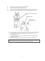
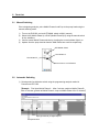
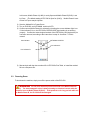
MOBILE PHASE SWITCHING
VALVE FOR HTEC-500
ELS-500
User Manual
Do not use the ELS-500 on humans or animals, except laboratory
animals, for the purpose of basic scientific research.
EiCOM CORPORATION
Headquarters (Japan): 113 Kita Enmenden-cho, Shimotoba, Fushimi-ku Kyoto, Japan, 612-8497
Phone: +81-75-622-2112
FAX : +81-75-622-2114
San Diego Office (USA): 7313 Carroll Road, Suite F, San Diego, CA 92121, USA
Phone: (888) 680-7775
FAX: (858) 560-8040
ELS500MAN_080
Introduction
Thank you for purchasing the Mobile Phase Switching Valve for the HTEC-500. The ELS-500 is
the switching valve which is developed and produced for exclusive use with the HTEC-500
HPLC-ECD System. This device allows the user to switch between two types of mobile phases at
the head pump of HTEC-500. The timing of the valve switching can be done either manually or by
external signal input.
We insist that users observe the following procedures in order to prevent accidents:
1) Be sure to read and understand this manual completely prior to operating the ELS-500.
2) Use the ELS-500 only for basic research purposes. Do not use on humans or animals, except
for laboratory animals.
3) Follow all warnings listed herein very closely.
4) Do not alter the ELS-500.
5) Never attempt to repair or dismantle the ELS-500 on your own.
WARNING
This device has been produced for experts who have knowledge
of chemical analysis and handling research reagents. Failure to follow instructions
may lead to poor quality data and could result in a safety hazard (such as fire, electric
shock, injury or other damage). DO NOT OPERATE the ELS-500 until reading and
understanding this instruction manual completely.
I. Parts List
1.1
Prior to operation, please ensure all of the following parts are included and that
the equipment has not been damaged in shipping.
Part
Manual
ELS-500(Main unit)
Valve Unit
Tefzel Tube (0.8mm ID) 150mm A NO Line
Tefzel Tube (0.8mm ID) 140mm B NC Line
Tefzel Tube (0.8mm ID) 75mm
COM Line
Tefzel Tube (0.8mm ID) 900mm for Mobile Phase
Flat Hex Fitting for Valve Unit
Quantity
1
1
1
1
1
1
2
3
Ferrule for Valve Unit
3
Flat Finger-tight Fitting for Degasser/3 Way Connector
5
Ferrule for Degasser/3 Way Connector
5
Signal Cable (For connecting the EPC-500 to the ELS-500)
Ground Wire
Power Supply Cable
1
1
1
- 1 -
WARNING
The ELS-500 and parts are not made for use in any other device
except the HTEC-500 HPLC-ECD system.
1.2 Parts Name and Function
Valve Unit
ELS-500 Main unit)
Switching Signal
Cable for Valve Unit
WARNING
The pressure limit of this Valve Unit is 200 kPa(0.2 MPa) and
CANNOT be used with ANY line that exceeds a pressure of 200 kPa.
Auto/Manual Switch
Automatic Indicator
Line Indicator A
Line Indicator B
Manual Switch for Line Indicators
ELS-500 Front
Power Switch
Ground Terminal
Fuse Case
Power Supply Socket
ELS-500 Back
- 2 -
External Automatic Control
Signal Input Terminal
Valve Unit Change Signal Socket
ELS-500 Bottom
1.3
Connecting to the HTEC-500
•
There are two degasser loops in the system which allows the mobile phase lines A
and B to be connected to the degasser in two ways, either before or after the
switching valve.
•
The ELS-500 controls the valve unit.
•
The timing of the switching can either be controlled by ELS-500’s manual switch or
can be programmed via external control signal using Eicom’s PowerChrom
EPC-500.
Control Signal Open/Close
PowerChrom
ELS-500
Control Signal
ELS-500 Valve Unit
HPLC-ECD System HTEC-500
Mobile Phase
Analysis System Configuration
- 3 -
1)
Flat Fitting Hold connector (Hexagon) connects the tubing to the valve unit.
To connect tubing to other devices, use Flat Fitting Hold connectors (Round).
Flange Ferrule
Fit tips of tubes
Hexagon
Connector
Tubing to Valve Unit
Ferrule (no fringe)
Fit tips of tubes
Round
Connector
Tubing to 3-way Connector/Degasser
2)
3)
4)
5)
6)
Locate the pump head inlet of the HTEC-500, and remove the connector from the
check valve
Pull the 3-way connector gently out of its bracket.
Loosen the 2 screws on the 3-way connector bracket and remove the bracket.
Connect the outlet port on the valve unit to the center outlet of the 3-way connector.
Attach the valve unit under the pump, using the 3-way connector bracket and screws.
- 4 -
7)
8)
9)
10)
Push the 3-way connector gently back into the bracket.
Connect the inlet check valve to the pump head.
Connect the line from mobile phase A to one of the inlet ports on the 3-way valve.
Connect the line from mobile phase B to the other inlet port on the 3-way valve.
Remove connector inlet check valve for
hook up
Connector (Hexagon)
3-way bracket
(Attached HTEC-500)
Line from
mobile
phase A
Line from
mobile
phase B
11) Connect the signal wire from the valve unit to the socket in the bottom of the ELS-500.
12) Connect terminal +/- of the bottom of ELS-500, to the terminal CTL 1 +/- of the
PowerChrom EPC-500.
13) The external device signal control of the ESP-500 must be set to OPEN/CLOSE on
CONTACT CLOSURE.
14) Remove the pin of the external signal terminal from the back of the ESP-500.
Please note that the method of switch the signals depends of the type of control device.
For the EPC-300, external device signal control is set by the DIP switch.
- 5 -
EPC-500 connector terminal
(Back)
ELS-500 connector terminal
(Back)
Valve unit
NO.1 PIN MUST BE PULLED OUT
- 6 -
II.
2.1
Parts List
Manual Switching
Prior to beginning analysis, prime Mobile Phases A and B up to the pump head using the
manual switching mode.
1)
2)
3)
4)
Turn on the ELS-500, and set AUTO/MAN. switch to MAN. (manual)
Select A NO (Mobile Phase A) or B NC (Mobile Phase B) by using the manual switch
for line indicators.
Confirm correct Mobile Phase selection by checking the correct indicator light is on.
Aspirate from the pump head to draw the Mobil Phase into each line respectively.
AUTO/MAN. Switch
Line indicator A
Line indicator B
Manual Switch for Line Indicators
2.2
Automatic Switching
1) Set automatic line indication switch using the programming analysis method in
PowerChrom EPC-500.
【Example: First inject Mobile Phase A. After 5 minutes, switch to Mobile Phase B.
After 10 minutes, go back to Mobile Phase A , keep on Mobile Phase A for 15 minutes】
Input (Open/Close) in Digital Output 1
Set injection time
- 7 -
In this case, Mobile Phase A (A NO) is set by Open and Mobile Phase B (B NC) is set
by Close. (The default setting of EPC-500 is Open for (A NO)). Mobile Phase A is set
to time 0:00 upon sample injection.
2) Save the Method file in PowerChrom.
3) Turn on ELS-500, set AUTO/MAN. switch to AUTO
4) Confirm correct Mobile Phase A is selected by checking the correct indicator light is on.
If Line Indicator B is on, the EPC-500’s OPEN/CLOSE signal setting is not working
properly. Confirm the external signal terminal of the ESP-500 by verifying that the pin
has been removed, according to the instructions in step 14 of section 1.3 of this
manual.
Auto indicator
AUTO/MAN. SWITCH
Line indicator A
Line indicator B
5) Start analysis with the above method file in EPC-500’s Run Table, or install the method
file into a sequence file.
2.3 Powering Down
To shut down the machine, simply turn off the power switch of the ELS-500.
WARNING
Do not leave machine powered on while set to Mobile Phase B
(B NC). The electromagnetic valve is always drawing an electrical current while the
machine is set to Mobile Phase B (B NC). If left powered on for long periods while set
to Mobile Phase B, the ELC-500 will be damaged.
- 8 -
III.
IV.
Specifications
Flows
Change-over switch
External digital input
Diversion valve
Valve pressure limit
Qty. 2
Manual/Automatic(External signal input)
Open Collector
Low Voltage Electromagnetic Valve
200kPa
Wetted material
Applied voltage
Weight
Daiflon/Tefzel/Perfluor
AC 100V 50/60Hz 10VA
1 kg
Limited Warranty
Warranty Period:
One year from the original purchase date as defined by the date of your Eicom
invoice. (Except for the valve unit – which is warranted for 6 months from the
purchase date as defined by the date of your Eicom invoice)
Warranty Information:
Void of Warranty:
During the warranty period, this Eicom product is covered by a limited
liability warranty covering manufacturer defects. In the case that the
machine is defective, it will be repaired or replaced free for charge.
The manufacturer’s warranty will be voided under the following conditions:
①
②
③
④
⑤
⑥
⑦
Failure to follow instructions and warnings relating to product’s use.
Repair or alteration by anyone other than Eicom.
Damage during shipping or transit, or any other accidental damage.
Damage due to use with hazardous voltages.
Damage due to improper connection of equipment.
Damage due to any act of God.
Any other inappropriate usage of parts or consumables that is not
authorized by Eicom.
All rights reserved. Use of images and/or wording of this manual without express permission is
completely prohibited. Specifications and descriptions in this user guide are subject to change
without prior notice. If you have any further questions, please feel free to contact Eicom or its
distributors.
- 9 -


![[PDF:0.6MB]](http://vs1.manualzilla.com/store/data/005664304_1-5124c75bfbffa9dc3657cce05bb0013f-150x150.png)