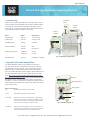
1
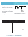
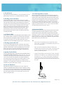
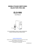
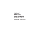
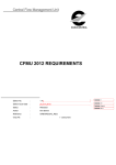
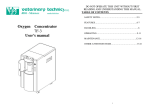
User’s Manual
AtmosLM Large Molecule Sampling Manual
1. System Set Up
Peristaltic
Pump
Figure 1 shows a typical AtmosLM setup. A syringe pump is used to
infuse perfusate and the peristaltic pump is used to withdraw sample
from the probe. Always keep the peristaltic pump (ERP-10) at the
same level as, or not more than 50cm above, the AtmosLM probe to
avoid reduced flow from the outlet line of the probe.
Name Syringe Pump (Push Pump)
Model ESP-32
ESP-64
Specification
1 motor 2 drive
2 motor 4 drive
Peristaltic Pump
ERP-10
2 channel
Syringe
Pump
Fraction
Collector
Fraction CollectorEFC-82Main
EFR-82Cooling Unit
Freely Moving System
ATFM-RA
for rats
ATFM-MAfor mice
AtmosLM Probe
PEP-X-Y
Polyethylen 1,000 kDa
Fig. 1 An Example of System Setup
2. Operation of Peristaltic Pump ERP-10
One RS-5S Peristaltic Tubing can be installed on each side of
the roller, upper and lower. Tubing Guide is the groove where the
peristaltic tubing, RT-5S, is placed. To move the tubing into place
against the rollers, please pull and slide the Knob until you hear a
click. The rotation speed shown in the display is NOT the RPM or flow
rate, but represents an indication of the rotation speed of the roller
head. When you use the RT-5S tubing and set the speed to “0020”,
the actual flow rate will be 1 µL/min. Do NOT place the ERP-10 higher
than approx. 50 cm, =20 inches above the probe to avoid the flow
fluctuations. In order to prolong the life of the RT-5S, please open the
Tubing Guides such that they don’t compress the tubing whenever the
pump is being stored.
Buttons and Actions
Up
Increases the rotation speed of roller.
Down
Decreases the rotation speed of roller.
CW/CCW Selects the direction of roller rotation, CW indicates
Clock Wise and CCW is Counter Clock Wise. If held
down for 3 seconds, the rotation speed will be set to
500. If held for 5 seconds, it will be to 1000.
Start/Stop Display
Operation Buttons
Tubing Guide
Roller
Knob
Fig. 2 Peristaltic Pump ERP-10
Starts or Stops the rotation of roller. If held down for
5 seconds, the input value will be memorized and the
same value will return after you reboot the unit.
US: eicom-usa.com, [email protected] | EU: eicomeurope.com, [email protected]
3. Tubing Setup
Connect all tubing as shown in Figure 3. Table1shows the model
names of tubing, size, material and approximately internal volume
of each tube shown in Fig.3. The tubing between the probe and
peristaltic pull pump has to be 0.25 mm ID to allow smooth withdrawal
of the sample.
5
7
6
3
4. Peristaltic Tubing
Please always use Eicom RT-5S for the tubing set on the ERP-10.
Please exchange RT-5S to new one at least every two (2) weeks if
you use every day. The lifetime for storage is 6 months. When you
do not use the ERP-10, please open the tubing guide to relieve the
pressure on the RT-5S.
RT-5S Includes
Peristaltic Tubing
Joint (#RTJ)
Internal Diameter
Total Length
1
4
2
Fig. 3 Tubing Diagram
Details of each tubing and parts on figure is explained on Table 1.
Please find corresponding number in the table and this figure.
5 pcs
4 pcs
0.25 mm
83 mm
Table 1. Information of Each Tubing
Model Name
1. Tubing from Syringe to Swivel
Size, Material
Approx. Volume
JT-10-50
0.1 mm ID x 50 cm, Teflon Tubing
Rat WT-35-40
0.1 mm ID x 40 cm, FEP
3.1 µL
Mouse WT-25-25
0.1 mm ID x 25 cm, FEP
0.6 µL
Rat WT-35-40
0.25 mm ID x 40 cm, FEP
20 µL
Mouse WT-25-25
0.25 mm ID x 25 cm, FEP
12 µL
4. Tubing from Swivel to ERP-10
JF-10-50
0.25 mm ID x 50 cm
25 µL
5. Tubing from ERP-10 to Fraction
Collector Needle
JT-10-50
+
FRN-JJ
0.1 mm ID x 50 cm Teflon
+
0.12 mm ID x 11 cm PEEK
4 µL
+
1.3 µL
6. Liquid Swivel
TCS2-21
0.45 mm ID for both in and out, Stainless Steel 316
7. Peristaltic Pump Tubing and Joints
RT-5S
RTJ
Tygon (Vinyl chloride) 0.25 mm ID x 83 mm
Stainless Steel 26G x 15 mm
JB-30
Biton 0.3 mm ID x your cut
2. Tubing from Swivel to Probe
3. Tubing from Probe to Swivel
Joint Tubing
4 µL
In 11 µL
Out 10 µL
Total 6 µL
Vary
Customized tube lengths are available for JT-10, JF-10 and WT-35.
Page 2 of 5
US: eicom-usa.com, [email protected] | EU: eicomeurope.com, [email protected]
5. You will need:
aCSF, BSA (Bovine Serum Albumin), 0.2 µm syringe filter, one 5 mL
plastic syringe, one 2.5 mL or 1 mL disposable syringe, ethanol
6. Flushing System with Water
Flush tubing with water to confirm the flow. At this point, please
bypass AtmosLM probe by using a small connector to join the tubing
where the probe will be located. If the traveling time of sample is
important, we recommend checking the actual traveling time on your
system setup. Insert an air gap in the tubing and run the system.
Many syringe pumps have a lag time between when the pump is
started at the controller and when the actual flow begins. This is
because there is a play in the cam and motor gear. So, please
first fast forward pump and then switch to normal flow rate before
connecting the tubing.
11. Connecting Probe to System
Both the syringe and peristaltic pumps should still be stopped and
flow rate settings of the syringe pump is at 10 µL/min and ERP-10 is
showing “0200”. Remove the bypass where the probe will be placed
and connect the inlet and outlet. Start the syringe pump and start the
peristaltic pump immediately after confirming a little leak fromt the
vent holes. Pay attention there might be a lag time on the syringe
pump caused by a mechanical play, see section 6. Confirm that an air
segment no larger than approx. 5 cm (= 2 inch, 2.5 µL) has entered
the outlet tubing. (see #3, #4 or #5 on Fig. 3).
12. Insertion of Probe
7. aCSF 0.15% BSA
Maintain the 10 µL/min flow rate and insert the probe into the animal
via guide cannula that has been implanted in advance. If dummy
probe is hard to remove, please twist and pull. Maintain the higher
flow rate for 2-3 hours in order to prevent clogging of the tubing. Then
lower the flow rate to 1 µL/min or your desired flow rate. If necessary,
refill the syringe of the syringe pump or switch the syringe by using a
liquid switching valve such as the SI-60.
8. Flushing System with aCSF
Tips
• Set the flow on the peristaltic pump 5% higher than syringe
pump. “0021” (=1.05 µl/min) for the peristaltic pump when 1 µL/
min on the syringe speed.
Prepare aCSF containing 0.15% BSA (Bovine Serum Albumin) on the
day of sample collection. Please do not include buffer components
such as carbonate or phosphate in aCSF. It will have more chance
to clog in the line during in Vivo use. Filter aCSF with a 0.2 μm
membrane filter and fill a Gastight Syringe using on a syringe pump.
A connector is still being used in place of the probe. Run both the
syringe pump and peristaltic pump at 10 times the normal sampling
flow rate to fill the system. To set the peristaltic pump at 10 μL/min,
please enter “0200” to the speed. After filling all lines without the
probe with aCSF/0.15% BSA, stop both pumps at the same time.
9. Quality Check of Probe
Connect a disposable plastic syringe filled with pure/distilled water to
the OUTLET (=shorter needle) of the probe. Only use a 1mL or 2.5
mL syringe. Larger syringes can easily generate too much pressure.
Then cover the probe’s vent holes with your fingers and depress
the syringe plunger gently to fill the probe. Water should be coming
out from Inlet needle. Confirm that there are no leaks from tip of
membrane or connecting parts of membrane or shaft. The surface of
membrane may have sweat, which is normal.
• When you lower the flow speed, stopping or lowering the
peristaltic pump first and then do the same on the syringe pump
to avoid a large air segment in the outlet tube which leads a
difficulty of withdrawing sample.
• Clogging mostly happens on the tubing #3 or oulet of the probe
after the vent. if it happens. To fix, please disconnect the swivel
and replace to a 1 mL syringe containg water at the tubing #3
out (see Fig.3 and Fig 4). Then infuse water toward the probe
via tubing #3. The flush will come out from the vent and you can
use water.
10. Activate Membrane
Submerge the membrane in ethanol (70% to 100%, it does not
matter) for 1 second. Do NOT keep the probes in ethanol for longer
than 5 seconds as this can damage the probe by weakening the glue.
The membrane is properly wetted when the opaque white membrane
becomes slightly translucent. Now use the plastic syringe to push
water into the probe again.
3
Fig. 4 Removing Clog
Page 3 of 5
US: eicom-usa.com, [email protected] | EU: eicomeurope.com, [email protected]
13. Maintenance
After completing sampling, remove the probe from the system and
bypass where the probe was. Open the Tubing Guide on the ERP-10
to prevent tubing occlusion and excess wear of the tubing. Run 50100 times diluted chlorine bleach in the entire tubing from the syringe
pump to the fraction collector and let it stand for at least 15 min. Then
disconnect all tubing and flush each piece of tubing with water. If you
plan on storing the tubing for more than a few days, run ethanol and
then air through the tubing, and store them dry.
Page 4 of 5
US: eicom-usa.com, [email protected] | EU: eicomeurope.com, [email protected]
Appendix 1. AtmosLM Guide Cannual Implant
Stereotaxic Appratus Adapotr (PESG-X), Guide Cannual (PEG-X), Dummy Cannual (PED-X), Anchor Screw (AN-3),
Cap Nut (AC-5)
1. Set Guide Cannual on Adaptor and Fix with a Cap
Cap Nut
(AC-5)
Nut.
Stero Adapter
(PESG-X)
Guide Cannula
(PEG-X)
2. Clamp the PESG-X
Please use standard electrode clamp which is provided from
your stereotaxic appratus manufacturer. Eicom does not carry
this part.
Model Number. Kopf 1770, 1771, 1773. Stoelting 51631,
51632, 51634.
Clamp of
Stereotaxic Apparatus
not provided from Eicom
3. Mount Cement
Guide cannula crouwn is made of acrylic resin and fuse with
cement. Cap Nut does not. Please mount dental cement below
the thread of the guide cannual.
Dental Cement
Ancor Screw (AN-3)
4. Replace Adaptor with Dummy Cannula
After confirming the cement is dry and firm, loose the cap nut
and remove the PESG-X from the PEG-X guide cannula. Then
put PED-X dummy cannula in to the guide and fasten the cap
nut.
Dummy Cannula (PED-X)
Page 5 of 5
US: eicom-usa.com, [email protected] | EU: eicomeurope.com, [email protected]