1
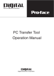
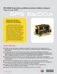
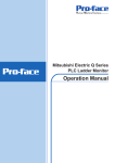
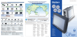
GP Series
CA1-PFSALL-21
(Profibus-DP Slave I/F Unit for GP2000)
User’s Manual
Pro-face Europe B.V.
CA1-PFSALL-21 User’s Manual
1
Table of Contents
Table of Contents
2
Essential Safety Precautions
3
Note on CE Marking
3
Package Contents
3
Chapter 1 – Introduction
CA1-PFSALL-21 Unit Specifications
4
External Dimensions
8
Component Names and Functions
9
Installation
10
Chapter 2 – Operation
Connectable GPs
11
Cable Diagram
12
Configuration as a Profibus-DP Slave
13
Chapter 3 – Diagnostics
Error Diagnostics
CA1-PFSALL-21 User’s Manual
14
2
Essential Safety Precautions
This manual includes procedures that must be followed to operate the CA1-PFSALL-21 Unit
and GP correctly and safely. Be sure to read this manual and any related materials thoroughly
to understand the correct operation and functions of the CA1-PFSALL-21 Unit and GP.
•
To prevent Internal Damage or Malfunction of the CA1-PFSALL-21 Unit:
• Be sure to use the CA1-PFSALL-21 Unit only within its designated operating
temperature range. Operating the CA1-PFSALL-21 Unit outside this range can
lead to breakdown or malfunction.
• Be sure that water, liquids or metal particles do not enter the CA1-PFSALL-21
Unit, since it may cause the unit to malfunction, or can lead to an electric shock.
• DO NOT store the CA1-PFSALL-21 Unit in a place where it will be exposed to
direct sunlight, high temperatures, excessive dust or vibration.
• The CA1-PFSALL-21 Unit is a high precision piece of equipment. DO NOT
subject it to excessive shocks.
• DO NOT store the CA1-PFSALL-21 Unit near chemicals, or where chemicals can
come into contact with the unit.
CE Marking
The CA1-PFSALL-21 is a CE marked product that conforms to EMC directives EN55011
class A and EN61000-6-2 .
Package Contents
The CA1-PFSALL-21 Unit’s packing box contains the items listed below. Please check to
confirm that all the items shown below have been included.
CA1-PFSALL-21
(Profibus-DP Slave I/F)
CA1-PFSALL-21
User’s Manual
GP Series
CA1-PFSALL-2 1
(Profibus-DP Slave I/F Unit)
User’s Manual
Pro-face HMI B.V.
This unit has been carefully packed, with special attention to quality. However, should you
find anything damaged or missing, please contact your local GP distributor immediately for
prompt service.
CA1-PFSALL-21 User’s Manual
3
Chapter 1 – Introduction
1.1 CA1-PFSALL-21 Unit Specifications
1.1.1
General Specifications
CA1-PFSALL-21
Power Supply
DC5V
Max Power
Consumption
350mA (Max)
When used with the models GP2300-TC41/LG41-24V, GP2301-LG/SC41-24V:
GP2300 Series + CA1-PFSALL-21
Rated Voltage
DC24V
Power Supply
DC19.2V ~ DC28.8V
Max Power
Consumption
24W (Max)
Voltage Endurance
Insulation Resistance
AC1000V 10mA for 1 minute (between charging and
FG terminals)
DC500V 20MΩ or higher (between charging and FG
terminals)
When used with the models GP2400-TC41:
GP2400 Series + CA1-PFSALL-21
Rated Voltage
DC24V
Power Supply
DC19.2V ~ DC28.8V
Max Power
Consumption
30W (Max)
Voltage Endurance
Insulation Resistance
CA1-PFSALL-21 User’s Manual
AC1000V 10mA for 1 minute (between charging and
FG terminals)
DC500V 20MΩ or higher (between charging and FG
terminals)
4
When used with the models GP2500/2600-TC41-24V, GP2501-LG/SC41-24V:
GP2500/2600 Series + CA1-PFSALL-21
Rated Voltage
DC24V
Power Supply
DC19.2V ~ DC28.8V
Max Power
Consumption
52W (Max)
Voltage Endurance
Insulation Resistance
1.1.2
AC1000V 10mA for 1 minute (between charging and
FG terminals)
DC500V 20MΩ or higher (between charging and FG
terminals)
Environmental Specifications
GP2000 Series + CA1-PFSALL-21
Ambient Operating
Temperature
Ambient Storage
Temperature
Operating Humidity
Operating Atmosphere
Grounding
Vibration (Non
Continuous)
Vibration (Continuous)
CA1-PFSALL-21 User’s Manual
0 °C to 50 °C
-20 °C to 60 °C
10%RH to 90%RH (no condensation)
Must be free of corrosive gasses
100Ω or less grounding resistance
10~57Hz 0.075mm, 57~150Hz 9.8m/s2
10~57Hz 0.035mm, 57~150Hz 4.98m/s2
5
1.1.3
External Specifications
CA1-PFSALL-21:
CA1-PFSALL-21
External Dimensions
109.9mm (W) x 105mm (H) x 19.0mm (D)
Weight
145g or less
Attachment Method
Attached to the back of GP
CA1-PFSALL-21 Module + GP Main Unit:
External
Dimensions
Weight
CA1-PFSALL-21
+
GP2300 Series
171mm (W) x
138mm (H) x
79 mm (D)
CA1-PFSALL-21
+
GP2400 Series
215mm (W) x
170mm (H) x
79 mm (D)
1245 or less
2645g or less
CA1-PFSALL-21
+
GP2500 Series
317mm (W) x
243mm (H) x
77 mm (D)
3645g or less
Attachment
Method
Mounted in a solid enclosure
Cooling
Method
Natural Air Circulation
CA1-PFSALL-21 User’s Manual
CA1-PFSALL-21
+
GP2600 Series
317mm (W) x
243mm (H) x
77 mm (D)
3645g or less
6
1.1.4
Profibus-DP Specifications
GP377-PF21
Protocol
PROFIBUS EN50170 & DIN 19245 Part 1
Medium
EIA RS485 twisted pair cable
Cable Type
Wire Gauge:
Conductor Area:
Supported Baud Rates
9.6, 19.2, 45.45, 93.75, 187.5, 500, 1500, 3000, 6000,
12000 kbit/s
Length of Cable*
0.64mm
> 0.34mm2
1200m @ 9.6 ~ 93.75 kbit/s extendible with repeaters
1000m @ 187.5 kbit/s extendible with repeaters
400m @ 500 kbit/s extendible with repeaters
200m @ 1.5 Mbit/s extendible with repeaters
100m @ 12 Mbit/s extendible with repeaters
* Valid for the Cable Type as specified above
Number of Nodes
32 Max in one segment, 127 possible with repeaters
(Including Master)
I/O per Slave
128 Bytes Input Max ( = 64 Words Max )
128 Bytes Output Max ( = 64 Words Max )
CA1-PFSALL-21 User’s Manual
7
1.2 External Dimensions
The CA1-PFSALL-21 Unit’s external dimensions are as follows:
(Unit: mm)
109.9mm
CA1-PFSALL-21 User’s Manual
3.7mm
19mm
8mm
8
1.2
Component Names and Functions
Node ID Selection
Connector for GP
Main Unit
Network Status LEDs
Termination Switch
Connector for
Profibus -DP Network
Notes:
NODE ID: This is coded in Hexadecimal, e.g. GP as slave No.1 => 01 (HIGH:0,
LOW:1), GP as slave No.31 => 1F (HIGH:1, LOW:F).
TERM: The first and last nodes on the Profibus-DP network should have their
termination switched on. Many Profibus-DP connectors have a built-in TERM switch,
then the GP377-PF21 TERM should be switched to the OFF position.
PWR led: Module Power indicator (see diagnostic section)
ERR led: Network Error Status indicator (see diagnostic section)
CA1-PFSALL-21 User’s Manual
9
1.4 Installation
WARNING: Prior to installing the CA1-PFSALL-21 Unit, be sure to check that the GP’s power
is OFF. Otherwise, it can cause an electric shock.
1.
Remove the GP unit’s expansion interface’s protective cover.
2.
Secure the CA1-PFSALL-21 Unit in place with its four (4) attachment screws (see figure).
A torque of only 0.5 to 0.6 Nm is needed.
CA1-PFSALL-21 User’s Manual
10
Chapter 2 – Operation
2.1 Connectable GPs
2.1.1
Connectable “Medium” Size GPs:
GP2301-LG41-24V
GP2301-SC41-24V
GP2300-LG41-24V
GP2300-TC41-24V
GP2400-TC41-24V
GP2501-LG41-24V
GP2501-SC41-24V
GP2500-TC41-24V
GP2600-TC41-24V
Note: CA1-PFSALL-21 Connects directly to the back of the bus connector on the GP
CA1-PFSALL-21 User’s Manual
11
2.2 Cable Diagram
2.2.1
Cable Diagram:
The CA1-PFSALL-21 Profibus-DP Slave units are connected via RS485 2-Line
connections. Please use the cable type as recommended in section 1.1.4. Below is
an example of wiring between two Profibus-DP Nodes.
CA1-PFSALL-21 User’s Manual
12
2.3 Configuration as a Profibus-DP Slave
2.3.1
Introduction to Profibus -DP:
Profibus-DP is a field bus network for control of remote I/O by a master (typically a
PLC). The master on the Profibus-DP network reads input and writes output data to
all the slaves on the network. The CA1-PFSALL-21 Unit is a Profibus-DP Slave. It
enables a GP to connect to a Profibus-DP network as a slave hence it is treated by
the Profibus-DP master as remote I/O.
2.3.2
Profibus-DP Master Configuration:
Each slave on the Profibus-DP network has to be entered into the Profibus-DP
master’s configuration. Here is defined the Input and Output size that the slave will
occupy and the Node ID for the slave. For this purpose each slave requires a unique
“GSD” file. This is an electronic description of the slave device. The CA1-PFSALL-21
has a GSD file also. The name is: GPE12982.GSD. This file can be found in the GPPRO/PBIII for Windows European Software v5.0 or later, otherwise please contact
your local Pro-face Supplier.
2.3.3
GP Configuration:
The Node ID has to be set on the CA1-PFSALL-21 module. This should be set to
match the Node ID assigned to it by the Profibus-DP master. Please note that the
Node ID on the CA1-PFSALL-21 is represented in Hexadecimal. Only the range 01h
~ 7Eh (1~126 decimal) are valid.
The Input & Output area size on the GP have also to match what was assigned by
the Profibus-DP master. These have to be configured using the GP-PRO/PBIII for
Windows Software. Please see the “PLC Connection Manual” and the documentation
on the CD-ROM for instructions.
CA1-PFSALL-21 User’s Manual
13
Chapter 3 – Diagnostics
3.1 Error Diagnostics
3.1.1
Status LEDs:
P
W
R
PWR LED Status
E
R
R
ERR LED Status
Error
Cause & Remedy
1.
OFF
OFF
No Power to the
Profibus Module.
2.
3.
1.
2.
ON (Green)
ON (Red)
Profibus -DP
Network Error.
3.
4.
5.
ON (Green)
OFF
CA1-PFSALL-21 User’s Manual
No Error
Module not connected properly to the
bus connector on the GP. Please
check that the mounting screws are
fixed firmly.
Module damaged. Contact your Proface dealer.
GP damaged. Contact your Pro-face
dealer.
Profibus -DP Master configuration not
present. Verify that the GP slave with
the error has been entered in the
master’s configuration and that the
correct GSD file has been used.
Node ID incorrect. Set the Node ID
on the module to match the master’s
configuration.
Cable Error. Verify that the cable is
connected properly to the GP unit
and the wiring is correct.
I/O Size Error. Verify that the GP’s
I/O size matches with that configured
by the master.
Termination incorrect. Verify that the
termination is only ON for the first and
last nodes. If the bus connectors
have a termination switch then turn
the termination OFF for all GPs.
Module and Profibus -DP network
configuration are OK !
14
3.1.2
GP Error Codes:
Error Code
Error Description
Cause & Remedy
1.
2.
02:14
Interface Module Hardware Error
3.
02:FF
1.
GP unable to send data.
Check that the cables are
connected correctly and that
the master is running.
1.
Cable error. Check Cable is
correct and connected
correctly.
PLC in stop mode. Data
cannot be received by the
GP while the PLC is in stop
mode.
Profibus -DP network not
active.
Interpreter function block
(FB99) not present or not
called in PACKET
TRANSFER mode. Check
PLC program.
Data Send Timeout
2.
02:FE
Date Receive Timeout
3.
4.
02:FC
02:FD
02:FA
CA1-PFSALL-21 User’s Manual
1.
Illegal Data Received by the
GP in PACKET TRANSFER
mode. Check the PLC
program and for bad cables
or noise on the bus.
1.
Illegal Data Received by the
GP in PACKET TRANSFER
mode. Check the PLC
program and for bad cables
or noise on the bus.
1.
Illegal address being
accessed by GP. Check
that the address type exists
and that the range is
supported by the PLC
Protocol Error
Data Error
Address out of range error
Interface module incorrect
type. Please replace.
Interface module not
connected. Securely mount
the module with the 3
mounting screws.
Interface module damaged.
Contact your Pro-face
supplier.
15
Pro-face European Headquarters
Pro-face HMI B.V.
Amsteldijk 166
1079 LH Amsterdam
The Netherlands
Tel: +31 (0)20 6464 134
Fax: +31 (0)20 6464 358
http://www.proface.com
[email protected]
Pro-face France
Pro-face France S.A.S.
Le Vinci 1, rue Henri Becquerel
77290 Mitry-Mory
France
Tel: +33 (0)1 60 21 22 91
Fax: +33 (0)1 60 21 22 92
Pro-face Germany
Pro-face Deutschland GmbH
Albertus Magnus Strasse 11
42719 Solingen
Germany
Tel: +49 (0)212 258 260
Fax: +49 (0)212 258 2640
Pro-face Italy
Pro-face HMI B.V. Italy
Via Carcano 44
20033 Desio (MI)
Italy
Tel: +39 0362 33 71 63
Fax: +39 0362 30 77 25
Pro-face Scandinavia
Pro-face Scandinavia ApS
Copenhagen Europe Center
Vesterbrogade 149
DK-1620 Copenhage V
Denmark
Tel: +45 (0)33 27 0616
Fax: +45 (0)70 27 0506
Pro-face UK
Pro-face UK, Ltd.
The Venture Centre, The Science Park
Coventry CV4 7EZ
United Kingdom
Tel: +44 (0)2476 692363
Fax: +44 (0)2476 692365
Manual: CA1-PFSALL-21-MAN-E01
CA1-PFSALL-21 User’s Manual
16