1
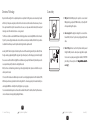
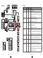
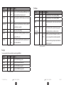
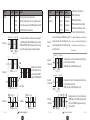
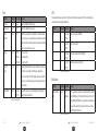
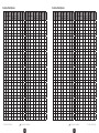
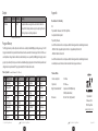
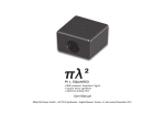
PI L SQUARED
MIDI powered, duophonic Synth
square wave synthesis
digital & analog filter
User Manual
Ploytec GmbH –
From Firmware Update V2.0
(PL2) Synthesizer - English Manual - Version 2.0, last revised: August 2014
Disclaimer
Contents
The information in this document is subject to change without notice and shall not be deemed as a warranty by the seller. No warranties, ex-
Introduction
4
Important Notes about Power Supply 4
At a Glance New Features with Firmware V2.0
5
Overview of Technology
6
tation, even if the possibility of such damage is known. The information in this document is subject to copyright. All rights are reserved. No part of this
Connectivity
7
manual may be reproduced or transmitted in any form or for any purpose without the expressed written permission of the copyright holders. Prod-
Signal Routing
8
uct and brand names contained in this document are used for identification purposes only. All registered trademarks, product designations or
Play Modes
9
pressed or implied, are made with regard to the quality, suitability or accuracy of this document. The manufacturer reserves the right to change
the contents of this document and/or the associated products at any time without the provision of prior notice to specific persons or organizations. The manufacturer shall not be held liable for damages of any kind arising from the use, or the inability to use this product or its documen-
brand names used in this document are the registered property of their respective owners.
©Ploytec GmbH, 2014. All rights reserved (01.08.2014).
Safety Instructions
Please only connect analogue audio connections when switched off, in order to protect the speaker membranes
and your hearing against sudden sound level peaks. Connecting the device to the USB port of your computer may
also cause a noise—please turn down the volume of your playback system accordingly.
2
Disclaimer (PL2) Synthesizer - English Manual
2
Envelope
10
Oscillators
11
Filter
14
LFO
15
Modulation
Modulation Wheel Bitpattern
15
16
Output
18
Program Memory
18
Fa c t o r y S o u n d s 18
Appendix
Declaration of Conformity
Technical Data Editor MIDI Implementation Chart
(PL2) Synthesizer - English Manual
3
19
19
19
20
22
Contents
3
Introduction
At a Glance - New Features with Firmware V2.0
We are pleased that you have chosen a Ploytec
(Pi Lambda squared 2 or simply PL2) synthesizer system for your musical
endeavors and would like to congratulate you on your decision. We’re convinced this innovative development will prove extremely useful to you in the coming years and, above all, provide you with a great deal of entertainment.
•
•
•
•
•
We hope you find this manual both informative and entertaining to read, and hope you find lots of pleasure in the Ploytec PL2
synthesizer system.
… Your Ploytec-Team!
•
•
•
Important Notes about Power Supply
The PL2 can generally be powered from the MIDI port without the need for a power adapter. You should ensure,
however, that the external MIDI device connected to this port can provide the required current. If this isn’t the case
you can use a common 5 Volt DC (100mA min.) USB power adapter (e.g. as commonly used for mobile phones)
and connect to the PL2 USB Micro-B port. Of course a standard PC or HUB USB port can provide the needed power
as well.
•
•
•
Now you can choose the MIDI channel and even the Omni mode (receive on all 16 channels) is available.
The range of notes can be limited by min. or max. values.
The startup program can be pre-selected within the editor software.
If the parameter [Digital Filter Cutoff ] is set to zero the key velocity will automatically control the filter cutoff.
The LFO modulation effects the filter with higher speed if the parameter [Note Priority] is set On. Especially for higher
played notes the new LFO speed results in an interesting sound impression.
Fine-Tuning is possible now. This is done by moving and holding the pitchbend wheel and simultaneously switching the
program (using the MIDI program change message) to set the new main pitch. Simply move the pitchbend wheel to the
min. or max. position to reset the pitch to its standard value.
MIDI Active Sensing is supported..
MIDI Polyphonic Aftertouch is supported. If your master keyboard or host application sends aftertouch information for
each note these will effect the volume (starting from the volume which is set by the velocity).
Shorter program switch-over times are realized.
A new Second Mode expands with three new waveforms and with the Bassdrum Mode. By using the MIDI-controller #3
(new) you can switch between the Normal and the Second Mode.
Four new preset programs are located on the program positions 4 and 22 to 24.
Power supply adapter and USB cables are not part of the scope of delivery.
4
Introduction
(PL2) Synthesizer - English Manual
4
(PL2) Synthesizer - English Manual
5
At a Glance - New Features with Firmware V2.0 5
Overview of Technology
Connectivity
Despite its small housing the PL2 is a complete duophonic mono synthesizer. The PL2 generates an enormous variety of sounds
with the help of two square wave (pulse) oscillators which can be interconnected in variable and innovative ways - these are
fun to experiment with. Not only the classic waveforms such as saw-, sine- or pulse-waves will be simulated, rather newly and
interesting sounds - from warm to destructive - are also generated.
The PL2 receives its data via a selectable MIDI channel and all setting parameters can be edited by MIDI controller commandos.
Up to 32 of your own self-programmed sounds can be stored in the user memory area. In addition, further 32 factory sounds are
located within a fixed memory area which provides ideal starting material to experiment with.
Generally, the PL2 follows the principle of subtractive synthesis in which the waveform (generated by the oscillators) first runs
through a wide range adjustable digital filter stage (low- high- and band-pass) to edit the frequency spectrum and/or amplify
the resonance area if desired. After the digital filter an additional analog low-pass filter follows which particularly ensures the
necessary warmth especially for destructive- and digital-like sounds.
Wait, there’s more: a dedicated analog saturation stage at the output provides dynamic compression and therefore a respectable bass punch is created.
1. MIDI jack. With the MIDI input jack it is possible to connect external
MIDI peripheral (e.g. keyboards, PC MIDI interfaces, etc.) Usually the PL2
will be powered through this jack also.
2. Audio output jack. The output jack is designed to be connected to unbalanced RCA (cinch) lines. If possible only use high quality RCA audio
cables.
1
2
3
3. Micro-B USB jack. In most cases the PL2 synthesizer will be powered
through the MIDI jack and no external power supply will be required.
You can connect a separate power supply (not included) or USB PC/HUB
port to this jack, if necessary. Also refer to ”�������������������������
Important Notes about Power Supply“ .
Of course the PL2 includes several additional options in terms of sound and playing manipulation like LFO modulation, PWM,
ADSR envelope and various play modes. Another interesting detail: LFO- and envelope-speed synchronise automatically to an
external applied MIDI clock - whereby the PL2 perfectly adjust to your song tempo.
For convenient and extended operation a software editor is available for Mac and PC. In addition, future PL2 synthesizer extensions or new features can be integrated by updating the firmware.
6
6
Overview of Technology
(PL2) Synthesizer - English Manual
(PL2) Synthesizer - English Manual
7
Connectivity
7
Signal Routing
Ch's Aftertouch
Key's Aftertouch
*(12)
MIDI Input
Aftertouch
Modulation
on/off
Attack
Breath
Contrl.
#2
Decay
#17
MIDI-Clock
MIDI Clock
Sync
*(12)
#89
A
#21
D
R
OSC Vol.
Playmode
Mono on
#126
Dual on
#127
Dual/Detune
#26
Dual/Octave
#27
Note-Priority
#89
Sustain
Hold
on/off
Key-Off
Attack
on/off
#64
#30
Volume
OSC 1
*(11)
*(10)
PWM 1
PWM 2
PWM 1&2
#25
#10
Portamento
Filter Link
ADSR
on/off
*(4)+(6)+(12)
#20
*(2)
*(1)
Portamento
Time
#5
Play Modes
*(5)
#16
S
Velocity
Note on/off
Release
Sustain
#19
#23
#24
OSC 2
on/off
#83
Volume
#65
#29
*(7)
Flt Cutoff
Digital
#18
Flt Reson.
Digital
#15
DC Offset
Filter
#22
Modulation
Wheel
#1
MIDI-Clock
LFO
Sync
Modulation
on/off
Amount
DAConversion
Modulation
on/off
ADSR Release
#31*
BP
*(5)
OSC Volume
#31*
BP
*(6)
Filter Resonance (Digital) #31*BP
*(7)
*(8)
Flt Cutoff
Analog
#14
PWM
#85
*(1)
Filter Cutoff (Analog)
#31*
BP
*(8)
Out Vol.
Pitch
#86
*(2)
Filter Cutoff (Digital)
#31*
BP
*(9)
Filter
#87
*(3)
PWM2
#31*
BP
*(10)
#7
Amp
#88
*(4)
PWM1
#31*
BP
*(11)
#31* : Refer to bitpattern table
BP
Signal Routing (PL2) Synthesizer - English Manual
8
Data Byte
Meaning
Mono On
126
0-127
Only oscillator 1 is active.
Dual On
127
0
Both oscillators (having equal phase positions) are active as soon as two
notes are played at the same time. If more than two notes are played
MIDI controller #89 sets the priority.
Dual/Detune
26 or 77
On: 0-63
Off: 64-127
Both oscillators have unequal phase positions.
[Off ] will switch back to the mono mode.
Filter Type
Digital
Dual/Octave
27 or 78
On: 0-63
Off: 64-127
Both oscillators have equal phase positions. Oscillator 2 is pitched one
octave lower than oscillator 1.
[Off ] will switch back to the mono mode.
Note Priority
89
On: 0-63
Off: 64-127
In dual modes the values up to 63 leading to play the both highest
notes. The values above 63 leading to play the both lowest notes and
one octave lower. Note: controller #89 switches [Aftertouch] also.
Aftertouch
89
On: 32-127
Off: 0-32
With values from 32 the aftertouch information will control the digital
filter cutoff. Note: controller #89 switches [Note Priority] also.
Breath Control
2
0-127
Like for [Aftertouch] breath control controls the filter cutoff. Note that
[Breath Control] and [Aftertouch] will overwrite each other.
Sustain Hold
64
On: 64-127
Off: 0-63
Hold function. If [On] is selected note-off commands are no longer
processed. A played note holds a fixed level - which is set by controller
#21 ([Sustain] of ADSR envelope) - until new notes occurs. This depends
on the particular mono-/ dual-mode.
#28
Saturation
Stage
Audio-Output
8
Status Byte
*(3)+(9)+(12)
DC Offset
Wave
on/off
Waveform
*(2)
(Velocity if 0)
Instruction
All values use decimal notation
(PL2) Synthesizer - English Manual
9
Play Modes
9
Oscillators
Instruction
Status Byte
Data Byte
Meaning
Key-Off Attack
30 or 81
On: 64-127
Off: 0-63
If [On] is set note off commands will generate ADSR envelope re-triggering. Interesting for bassy and percussive sounds.
Instruction
Status Byte
Daten Byte
Meaning
PWM 1
25 or 76
0-127
Pulse width modulation 1, will be overwritten by [PWM 1&2].
Portamento
65
On: 64-127
Off: 0-63
Glide. A new played note will slide from the previous to the new target
pitch.
PWM 2
23 or 95
0-127
Pulse width modulation 2, will be overwritten by [PWM 1&2].
PWM 1&2
10
0-127
Portamento Time
5
0-127
If [Portamento] is selected this parameter controls the speed at which
an oscillator moves to a new pitch.
Pulse width modulation 1&2, controls in absolute and not in relative
terms.
0-127
120
0
Silence all notes currently sounding.
OSC Volume
(Pre Filter Volume)
20 or 92
All Sound Off
Oscillator maximal level. The velocity and the envelope generator
(ADSR) modulate the volume to a maximum level set here.
All Notes Off
123
0
Turns off all voices. A note-off message will address each note to stop
hanging sounds if necessary.
DC Offset Wave
83
On: 64-127
Off: 0-63
Second Mode
3
On: 01
Off: 00
The Second Mode expands the PL2 with three additional waveforms
and a special Bassdrum Mode.
Bitshifter. The waveform will be shifted upwards by a fixed level set
here. As soon the upper limit is reached the truncated part will be
inserted at the lower limit again. Thereby distorted and destructive
sounds can be generated.
All values use decimal notation
All values use decimal notation
Envelope
The envelope speed will synchronise automatically to an externally applied MIDI clock.
Instruction
Status Byte
Data Byte
Meaning
ADSR Attack
17 or 73
0-127
Rise time of the ADSR envelope generator.
ADSR Decay
19 or 91
0-127
Decay time of the ADSR envelope generator.
ADSR Sustain
21 or 93
0-127
Hold level of the ADSR envelope generator.
ADSR Release
16 or 72
0-127
Release time of the ADSR envelope generator.
All values use decimal notation
10
Play Modes & Envelope
(PL2) Synthesizer - English Manual
10
(PL2) Synthesizer - English Manual
11
Oscillators
11
Instruction
Status Byte
Data Byte
Meaning
Instruction
Status Byte
Data Byte
Meaning
Waveform
24 or 75
1: 0-31
2: 32-63
3: 64-95
4: 96-127
1: Oscillation period 1 and 2 have the same pitch.
2: The pitch of oscillation period 2 is one octave higher than period 1.
3 and 4: Complex square wave forms - [PWM 1] adjusts the lower half
wave, [PWM 2] adjusts the upper half wave.
Waveform
Second Mode
24 or 75
1: 0-31
2: 32-63
3: 64-95
4: 96-127
1: Bassdrum Mode
2: Undevizesime
3: Quartvizesime
4: Clubvizesime.
All values use decimal notation
Osc. Period 1
Osc. Period 2
Waveform 1
PWM 1
PWM 2
All values use decimal notation
Each repetitive waveform consists of two separate oscillation periods. [PWM1] adjusts the first and [PWM2] adjusts the second pulse.
[PWM1] and [PWM2] modify the complete waveform (consisting of
two oscillation periods) using a special combination algorithm.
Bassdrum
Mode
D = 50% - 100%
Osc. Period 1
A+B
A
Resulting waveform combined
by A and B. The pitch of B is one
octave higher than A. [PWM 1]
adjusts A and [PWM 2] adjusts B.
PWM 1 D = 75% - 100%
Waveform 2
B
PWM 2
PWM 2
D = 75% - 100%
Oscillators PWM 2
(PL2) Synthesizer - English Manual
12
control the noise. [Out Volume] and [DC Offset Filter] control
the kick and the noise. Some controllers are not used in
Bassdrum Mode. Resulting waveform consists of two oscillation periods. The pitch of period 2 is the 19th interval of period 1.
[PWM 1] adjusts period 1 and [PWM 2] adjusts period 2.
PWM 1
PWM 2
D = 50% - 100%
Osc. Period 1
Osc. Period 2
Waveform
Quartvizesime
Resulting waveform consists of two oscillation periods. The pitch of period 2 is the 24th interval of period 1.
[PWM 1] adjusts period 1 and [PWM 2] adjusts period 2.
PWM 2
D = 50% - 100%
PWM 2
D = 75% - 100%
Resulting waveform consists of two oscillation periods.
[PWM 1] adjusts period 1, [PWM 2] adjusts period 2 and
effects its pitch. [PWM2] thus generates an interesting
pitch-sound effect.
Waveform
Clubvizesime
PWM 1
D = 75% - 100%
The digital filter, the ADSR envelope and [OSC Volume] only
Osc. Period 2
Waveform
Undevizesime
PWM 1
Waveform 4
PWM 1
12
B = A + 1 Oktave
D = 75% - 100%
Waveform 3
The lower part of the keyboard (to MIDI note F3) plays the
bassdrum sound. Notes above (from F#3) generate a noise
sound. The played pitch effects the bassdrum sound but
doesn’t effect the noise.
Bassdrum Mode controller allocation:
[PWM1]: Bassdrum Timbre
[PWM2]: Bassdrum Kick Attack
[PWM1&2]: Bassdrum Timbre & Kick-Attack
[DC Offset Wave]: Bassdrum Release Sound
[Portamento Time]: Bassdrum Release Time
PWM 1 PWM 2
D = 75% - 100%
13
Oscillators (PL2) Synthesizer - English Manual
13
Oscillators
13
Filter
LFO
The integrated low frequency oscillator (LFO) can effect up to five destination parameters. The LFO speed will synchronise
automatically to an externally applied MIDI clock.
Instruction
Status Byte
Daten Byte
Meaning
Filter Cutoff
18 or 74
0-127
Adjusts the digital filter cutoff frequency.
Filter Resonance
15 or 71
0-127
Amplifies the digital filter resonance area.
Instruction
Status Byte
Data Byte
Meaning
DC Offset
(Post Filter)
22 or 94
0-127
Bitshifter. The waveform after the digital filter can be shifted upwards
by a level set here. As soon the upper limit is reached the truncated part
will be inserted at the lower limit again. Thereby experimental sounding
tones can be generated here once more.
PWM
85
On: 64-127
Off: 0-63
Controls the parameter [PWM 1&2].
Pitch
86
On: 64-127
Off: 0-63
Controls the main pitch.
Filter
87
On: 64-127
Off: 0-63
Controls the parameter [Filter Cutoff Digital].
Amp
88
On: 64-127
Off: 0-63
Controls the parameter [OSC Volume].
Filter Type
28 or 79
LP: 0-63
BP: 64-95
HP: 96-127
LP = low pass filter
BP = band pass filter
HP = high pass filter
Filter Cutoff
(Analog)
14 or 70
0-127
After the digital filter and DA conversion, an additional analog low-pass
filter follows. The analog filter cutoff frequency is adjusted here.
Note : this parameter isn‘t useful for dynamic control because disturbing noises can occur while playing notes and changing this parameter
at the same time.
Filter Link ADSR
29 or 80
On: 64-127
Off: 0-63
The amplifier envelope can control the digital filter cutoff frequency if
linked. [On] will activate the link.
All values use decimal notation
All values use decimal notation
Modulation
Instruction
Status Byte
Data Byte
Meaning
Modulation Wheel
Mode
31 or 82
0-127
Bitpattern
Up to seven destination parameters can be effected by the modulation
wheel: [ADRS Release], [OSC Volume], [Filter Resonance], [Filter Cutoff
Analog, [PWM 1] and [PWM 2] can be assigned in form of an bitpattern
to any possible combination. The desired combination can be taken
from the “Bitpattern“ table chart.
All values use decimal notation
14
Filter (PL2) Synthesizer - English Manual
14
(PL2) Synthesizer - English Manual
15
LFO & Modulation 15
Modulation Wheel Bitpattern
DatenByte
00
01
02
03
04
05
06
07
08
09
10
11
12
13
14
15
16
17
18
19
20
21
22
23
24
25
26
27
28
29
30
31
ADSR
Release
OSC
Volume
Filter
Reson.
(Digital)
P
P
P
P
P
P
P
P
P
P
P
P
P
P
P
P
16 Modulation Wheel Bitpattern
Filter
Cutoff
(Analog)
P
P
P
P
P
P
P
P
P
P
P
P
P
P
P
P
Modulation Wheel Bitpattern
Filter
Cutoff
(Digital)
P
P
P
P
P
P
P
P
P
P
P
P
P
P
P
P
PWM 2
P
P
P
P
P
P
P
P
P
P
P
P
P
P
P
P
PWM 1
DatenByte
ADSR
Release
32
33
34
35
36
37
38
39
40
41
42
43
44
45
46
47
48
49
50
51
52
53
54
55
56
57
58
59
60
61
62
63
P
P
P
P
P
P
P
P
P
P
P
P
P
P
P
P
(PL2) Synthesizer - English Manual
16
OSC
Volume
P
P
P
P
P
P
P
P
P
P
P
P
P
P
P
P
P
P
P
P
P
P
P
P
P
P
P
P
P
P
P
P
Filter
Reson.
(Digital)
P
P
P
P
P
P
P
P
P
P
P
P
P
P
P
P
Filter
Cutoff
(Analog)
P
P
P
P
P
P
P
P
P
P
P
P
P
P
P
P
Filter
Cutoff
(Digital)
P
P
P
P
P
P
P
P
P
P
P
P
P
P
P
P
PWM 2
P
P
P
P
P
P
P
P
P
P
P
P
P
P
P
P
PWM 1
P
P
P
P
P
P
P
P
P
P
P
P
P
P
P
P
DatenByte
ADSR
Release
64
65
66
67
68
69
70
71
72
73
74
75
76
77
78
79
80
81
82
83
84
85
86
87
88
89
90
91
92
93
94
95
P
P
P
P
P
P
P
P
P
P
P
P
P
P
P
P
P
P
P
P
P
P
P
P
P
P
P
P
P
P
P
P
OSC
Volume
Filter
Reson.
(Digital)
P
P
P
P
P
P
P
P
P
P
P
P
P
P
P
P
Filter
Cutoff
(Analog)
P
P
P
P
P
P
P
P
P
P
P
P
P
P
P
P
Filter
Cutoff
(Digital)
P
P
P
P
P
P
P
P
P
P
P
P
P
P
P
P
PWM 2
P
P
P
P
P
P
P
P
P
P
P
P
P
P
P
P
PWM 1
P
P
P
P
P
P
P
P
P
P
P
P
P
P
P
P
DatenByte
ADSR
Release
OSC
Volume
96
97
98
99
100
101
102
103
104
105
106
107
108
109
110
111
112
113
114
115
116
117
118
119
120
121
122
123
124
125
126
127
P
P
P
P
P
P
P
P
P
P
P
P
P
P
P
P
P
P
P
P
P
P
P
P
P
P
P
P
P
P
P
P
P
P
P
P
P
P
P
P
P
P
P
P
P
P
P
P
P
P
P
P
P
P
P
P
P
P
P
P
P
P
P
P
(PL2) Synthesizer - English Manual
17
Filter
Reson.
(Digital)
P
P
P
P
P
P
P
P
P
P
P
P
P
P
P
P
Filter
Cutoff
(Analog)
P
P
P
P
P
P
P
P
P
P
P
P
P
P
P
P
Filter
Cutoff
(Digital)
P
P
P
P
P
P
P
P
P
P
P
P
P
P
P
P
PWM 2
P
P
P
P
P
P
P
P
P
P
P
P
P
P
P
P
PWM 1
P
P
P
P
P
P
P
P
P
P
P
P
P
P
P
P
17 Modulation Wheel Bitpattern
Output
Appendix
Instruction
Status Byte
Data Byte
Meaning
Out Volume
7
0-127
The output includes an analog volume control which is linked commonly with the following saturation stage. The output signal therefore
gets rising compression by rising output level.
All values use decimal notation
Program Memory
The PL2 program memory includes 64 positions which can be selected by standard MIDI program change messages. The first
32 programs include the factory sounds which are fixed and cannot be overwritten. The memory space from 33 to 64 is the user
area. All parameter changes made here will be stored automatically as soon as you switch (via MIDI program change) to another
program. Upon delivery the factory sounds can be found additionally at program position 33-64 and therefore provides ideal
starting material to experiment with. The program numbers 65-128 include random sounds.
Factory Sounds
* new with Firmware V2.0 - ROM only
Progr. Name
18
We:
Ploytec GmbH • Fahrnauerstr. 64 • 79650 Schopfheim
hereby declare that the product
Ploytec PL2 Synthesizer ,
to which this declaration refers is in compliance with the following standards or standardising documents:
• EN 55022: 1998+Corrigendum July 2003+A1:2000+ Corrigendum April 2003+A2:2003
• EN 55024: 1998+A1:2001+A2:2003
to which this declaration refers is in compliance with the following standards or standardising documents:
residential, business and commercial environments and small-company environments.
Technical Data:
Progr. Name
Progr. Name
Progr. Name
1
Upright Bass
9
Main Bass
17
Analog Bass
25
Geiger
2
Analog Synth
10
On Air
18
Signals
26
Metropolis
3
Lord
11
Black Roses
19
Mr. Finger
27
Vettel
4
Cempilo*
12
Poison
20
Dead Cat
28
Analog Pad
5
Analog Strings
13
5th down
21
Titanium
29
Lukas
6
Summer Bass
14
Dub Bass
22
Neon Wobble*
30
Transformator
7
Will You
15
Charles
23
PR-L08*
31
Smacker
8
Berlin 61
16
Wesley
24
PR-L09*
32
Electric Moskito
Output & Program Memory
Declaration of Conformity
(PL2) Synthesizer - English Manual
18
Current consumption:
Output level: Digital “State Variable Filter“: Dimensions: 10mA max.
580mVRMS (nom.)
Samplerate: 125kHz (Waveforms), 50kHz (Bassdrum Mode)
46.5 x 27.5 x 52.0 [mm] (wxhxd)
(PL2) Synthesizer - English Manual
19
Ploytec GmbH
Fahrnauerstr. 64
79650 Schopfheim
w w w.ploytec.com
Appendix
19
Editor
(fast mode: approx. 3s, normal mode: approx. 7s and save mode: approx. 32s). Reduce the speed if transfer problems occur.
The editor lets you comfortably edit all PL2 parameters on your Mac or PC. Additionally, it is possible to select, play and even record short demo sequences. Future feature enhancements can be implemented to the PL2 by using the editors firmware update
facility. Because the communication runs through your own MIDI interface it is possible to set the transfer speed in three steps
Note: unlike a standard MIDI control change message each program will not be saved automatically when using the editor for
switching. Use the dedicated Save button here.
20
Appendix (PL2) Synthesizer - English Manual
20
(PL2) Synthesizer - English Manual
21
Appendix
21
MIDI Implementation Chart
[PL2 (PI L SQUARED) duophonic square wave synth]
Date:01.08.2014
PL2 MIDI Implementation Chart
+--------------------+-------------+-------------+--------------------------------------+
|
Function
| Transmitted | Recognized |
Remarks
|
+--------------------+-------------+-------------+--------------------------------------+
|Basic
Default
|
x
|
1-16
|
|
|Channel
Changed
|
x
|
x
|
|
+--------------------+-------------+-------------+--------------------------------------+
|
Default
|
x
|
Mode 3
|
|
|Mode
Messages |
x
| POLY, MONO |
|
|
Altered
|*************|
x
|
|
+--------------------+-------------+-------------+--------------------------------------+
|Note
|
x
|
0-127
|
|
|Number: True Voice |*************|
0-127
|
|
+--------------------+-------------+-------------+--------------------------------------+
|Velocity Note On
|
x
| o 1-127
|
|
|
Note Off |
x
|
x
|
|
+--------------------+-------------+-------------+--------------------------------------+
|Aftertouch Key‘s
|
x
|
x
|
|
|
Ch‘s
|
x
|
x
|Volume Control
|
+--------------------+-------------+-------------+--------------------------------------+
|Pitch Bender
|
x
|
o
|-12<-0->+12 semi, 8 bit resolution *2|
+--------------------+-------------+-------------+--------------------------------------+
|
1|
x
|
o
|Modulation Wheel
*3|
|
2|
x
|
o
|Breath Control
*4|
|
3|
x
|
o
|Mode Select (Second/Normal)
*15|
|
5|
x
|
o
|Portamento Time
|
|
7|
x
|
o
|Out Volume
|
|Control
10|
x
|
o
|PWM 1 & 2
*5|
|Change
14, 70|
x
|
o
|Filter Cutoff - Analog
|
+--------------------+-------------+-------------+--------------------------------------+
22
Appendix (PL2) Synthesizer - English Manual
22
+--------------------+-------------+-------------+--------------------------------------+
|
Function
| Transmitted | Recognized |
Remarks
|
+--------------------+-------------+-------------+--------------------------------------+
|
15, 71|
x
|
o
|Filter Resonance - Digital
|
|
16, 72|
x
|
o
|ADSR Release
|
|
17, 73|
x
|
o
|ADSR Attack
|
|
18, 74|
x
|
o
|Digital Filter Cutoff
|
|
19, 91|
x
|
o
|ADSR Decay
|
|
20, 92|
x
|
o
|OSC Volume (Pre Filter Volume)
|
|
21, 93|
x
|
o
|ADSR Sustain
|
|
22, 94|
x
|
o
|DC Offset (Post Filter)
|
|
23, 95|
x
|
o
|PWM 2
*6|
|
24, 75|
x
|
o
|Waveform
*1|
| Control
25, 76|
x
|
o
|PWM 1
|
| Change
26, 77|
x
|
o
|Dual/Detune
*1|
|
27, 78|
x
|
o
|Dual/Octave
*1|
|
28, 79|
x
|
o
|Filter Type - Digital
*1|
|
29, 80|
x
|
o
|Filter Link ADSR
*1|
|
30, 81|
x
|
o
|Key-Off Attack
*1|
|
31, 82|
x
|
o
|Modulation Wheel Mode
*7|
|
64|
x
|
o
|Sustain Hold
*1|
|
65|
x
|
o
|Portamento
*1|
|
83|
x
|
o
|DC Offset (Pre Filter)
*1|
|
85|
x
|
o
|PWM Modulation (LFO)
*1|
|
86|
x
|
o
|Pitch Modulation (LFO)
*1|
|
87|
x
|
o
|Filter Modulation (LFO)
*1|
|
88|
x
|
o
|Amp Modulation (LFO)
*1|
|
89|
x
|
o
|Note Priority and Aftertouch
*8|
|
120|
x
|
o
|All Sound Off
*1|
|
123|
x
|
o
|All Notes Off
*1|
+--------------------+-------------+-------------+--------------------------------------+
(PL2) Synthesizer - English Manual
23
Appendix
23
+--------------------+-------------+-------------+--------------------------------------+
|
Function
| Transmitted | Recognized |
Remarks
|
+--------------------+-------------+-------------+--------------------------------------+
|Program
|
x
| o 0-63
|
|
|Change True Number |*************|
0-63
|
*9|
+--------------------+-------------+-------------+--------------------------------------+
|System Exclusive
|
x
|
o
|
*10|
+--------------------+-------------+-------------+--------------------------------------+
|System SongPosition|
x
|
x
|
|
|Common SongSelect |
x
|
x
|
|
|
Tune
|
x
|
o
|
*11|
+--------------------+-------------+-------------+--------------------------------------+
|System
Clock
|
x
|
o
|
*12|
|Real Time
Commands|
x
| o Start
|
*13|
+--------------------+-------------+-------------+--------------------------------------+
|Aux
:Local On/Off |
x
|
x
|
|
|Mes- :All Notes Off|
x
| o 1-127
|
|
|sages :Active Sense |
x
|
o
|
|
|
:Reset
|
x
|
o
|
*14|
+--------------------+-------------+-------------+--------------------------------------+
24
Appendix (PL2) Synthesizer - English Manual
24
+--------------------+-------------+-------------+--------------------------------------+
|Notes
|
| *1: Switch
|
| *2: Pitch Wheel Change (E0 hex). MSB and bit 0 of LSB used
|
| *3: Effects parameters according to bitpattern table (defined in controller #31, 82)
|
| *4: Overwrites Aftertouch information and vice-versa
|
| *5: Overwrites PWM 1 (controller #25, 76) and PWM 2 (controller #23, #95)
|
| *6: Effective only for waveform 2-4 (controller #24, 75)
|
| *7: Defines modulation wheel routings according to bitpattern table
|
| *8: Controller #89 sets both, Aftertouch (bit 5) and Note Priority (bit6)
|
| *9: 0-31 (program 1-32) is fixed factory set, 32-63 (program 33-64) is user set
|
|*10: Used for future system exclusive firmware updates
|
|*11: Reset to start-up condition
|
|*12: Synchronising LFO clock and ADSR speed. Once linked a loosing clock signal will
|
|
cause a complete system reset!
|
|*13: LFO restart
|
|*14: Reset to start-up condition
|
|*15: Mode Select: 0 = normal mode, 1 = second mode, 2-127 undefined
|
+---------------------------------------------------------------------------------------+
Mode 1 : OMNI ON, POLY
Mode 2 : OMNI ON, MONO
o :Yes
Mode 3 : OMNI OFF, POLY
Mode 4 : OMNI OFF, MONO
x :No
(PL2) Synthesizer - English Manual
25
Appendix
25