1
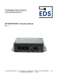
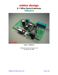
HA5-User Manual
ASCII RS232/RS485/TTL to 1-Wire® Host Adapter
http://www.EmbeddedDataSystems.com
FEATURES
ASCII command support for all 1-Wire devices.
RS232, RS485 or TTL interface options.
Parasitically (RS232) or externally powered.
Automatically adjusts for variable 1-Wire bus conditions.
Automatically provides smart strong-pull-up for sensors.
2000 feet, 200 devices per CAT-5 twisted pair 1-Wire bus.
Supports up to 26 1-Wire networks per host serial port.
User selectable Baud rates from 1200 to 115K Baud.
User selectable address (1 of 26).
User selectable error-check mode.
RS232 version supports Broadcast Radio and Modem applications.
Built-in DB9 for RS232/RS485/TTL interface.
Optional RJ11 or screw-down 1-Wire bus interface connector options.
Provides Search, Conditional Search and Family Search commands.
Supports Touch Memory File Structure for iButtons.
Automatically generates and checks CRC16 for TMEX files.
Block mode commands support all 1-Wire device functions.
ESD Protection more than 27kV (IEC801-2 Reference Model.) on the
1-Wire bus.
Optional enclosure.
DESCRIPTION
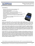
The HA5 is an RS232, RS485 or TTL to 1-Wire interface, which provides an ASCII command set for embedded controller
and DOS based applications that need to accommodate Dallas Semiconductor iButton and 1-Wire devices. The HA5
relieves the host of the burden of generating the time–critical 1–Wire communication waveforms while supporting all 1Wire devices with simple ASCII commands that can be easily generated. The HA5 does all the hard work of interfacing 1Wire networks. RS232, RS485 and TTL versions provide as many as 26 1-Wire networks from a single host serial-port,
broadcast radio or modem. The HA5 can perform Search, Conditional search and Family search functions making it
easy to acquire the unique 64 bit serial numbers of all connected devices. The HA5 constantly performs a dynamic
analysis of the network and adjusts the network timing to allow for variable conditions. This results in good performance
with both short and long networks with many or only a few devices attached. Many sensor devices require that extra
power be delivered during periods of data conversions (DS1920 and DS1820 temperature sensors for example). The HA5
automatically provides the extra current these devices require with a built in smart strong-pull-up. Dallas Semiconductor
iButtons which store data in TMEX Touch Memory File format can be read or written with simple ASCII commands. The
HA5 will automatically generate and check the CRC16 error checks from Touch Memory File records. The HA5 supports
analog, digital, and temperature 1-Wire devices and all Dallas Semiconductor iButtons.
1-Wire® and iButton® are registered trademarks of Dallas Semiconductor. TMEX™ is a trademark of Dallas
Semiconductor.
Embedded Data Systems, LLC.; 2019 Fortune Drive; Lawrenceburg, KY 40342; Phone/Fax 502-859-5490
1-33
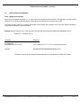
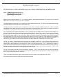
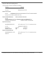
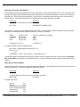
HA5 Command format:
Command
Response
Address[command][Checksum][CR]
[Data][Checksum][CR]
The HA5 is an addressed command/response device. To get a response the user must send a command with the proper
address command and checksum. The HA5 will respond with data and a checksum. All commands and responses end
with a CR (hex 0D) character. The “Address” is a single character “a” to “z” which is set by onboard switch positions A0A4. The checksum is a mod 256 sum of all the ASCII character values in the command or response but does not include
the CR. For development purposes the user can disable the checksum, in this case the checksum field is not present in
either the command or the response. All commands, data and checksums are in ASCII hexadecimal format.
Each HA5 on the host serial port, in a broadcast radio network or on a TTL connection must have the address switches
A0-A4 set to a unique setting. This allows as many as 26 1-Wire busses to be created from a single serial port. Each
HA5 will respond to the unique single character “a”- “z” address resulting from the switch settings A0-A4 (see addressswitch table). In RS232 mode the HA5 uses the address capability to support broadcast radio applications. In RS485 and
TTL modes the address is used to enable a selected HA5 which is hard wired to the host serial port. Address mode
cannot be disabled. An application that needs only a single HA5 still must send the correct address “a”-“z” which results
in a match with the corresponding address switches A0-A4.
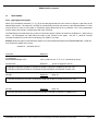
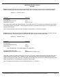
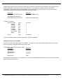
The HA5 will respond with an error code (BEL, hex 07) followed by a <CR> (hex 0D) if an error is encountered while
attempting to execute the given command. No response is given to commands that are addressed to another device or
that have errors resulting in a checksum failure. Host receive timeout is the suggested manner of recovery from these
errors.
Error Format:
Command
Response
Address[command][Checksum][CR]
[BEL][Checksum][CR]
Embedded Data Systems, LLC.; 2019 Fortune Drive; Lawrenceburg, KY 40342; Phone/Fax 502-859-5490
2-33
HA5 Command List
'S'
SEARCH ROM:
Allows the HA5 to use a process of elimination to identify the 64–bit ROM codes of all slave devices on the bus.
'C'
CONDITIONAL SEARCH (ALARM SEARCH):
Search command, except that, only devices fulfilling a specific condition will participate in the search.
'F'
FAMILY SEARCH:
Search command, except that only the device with a matching family code will participate in the search.
'A'
ADDRESS Select:
Selects a device on the 1-Wire bus with a matching 64-bit ROM code.
'B'
WRITE/READ BIT:
This command allows a single bit, either zero (0) or one (1) to be written or read on the bus.
'R'
1-WIRE RESET:
The Reset command generates a reset pulse and determines if any slave devices are on the 1-Wire bus.
'N'
READ ANALOG CHANNEL:
Allows 12-bit analog data to be read from EDS multi-channel analog input boards and sensor probes.
'Q'
READ 8-ANALOG CHANNELS:
Allows eight 12-bit analog data channels to be read from EDS multi-channel analog input boards.
'G'
READ PAGES:
Allows any number of consecutive pages of data to be read from an iButton or 1-Wire memory device.
'L'
READ FILE RECORDS:
Allows any number of TMEX™ file records of data to be read from an iButton or 1-Wire memory device.
'I'
WRITE File RECORD AT PAGE, WITH CRC16:
Write to 1-Wire devices and iButtons in Touch Memory File Structure records.
'W'
WRITE BLOCK, 'K' RESET AND WRITE BLOCK, and 'J' RESET, ADDRESS DEVICE, AND WRITE BLOCK:
Similar to the write/read bit command on blocks of up to 32 bytes.
'V'
READ TEMPERATURE OF SELECTED DS1820 or DS1920:
Performs a temperature conversion and reads the 8-byte scratchpad memory of a DS1820/DS1920.
'D'
READ DS2407 Channel Info:
Reads the channel info byte of a selected DS2407.
'DR'
READ DS2407 Channel Info with activity-latch-reset:
Resets the activity latches and reads the channel info byte of a selected DS2407.
'E'
WRITE DS2407 DIGITAL OUTPUTS:
Writes DS2407 digital outputs with a CRC16 error check before write.
Embedded Data Systems, LLC.; 2019 Fortune Drive; Lawrenceburg, KY 40342; Phone/Fax 502-859-5490
3-33
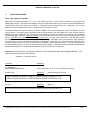
Search ROM Command
'S'
SEARCH ROM
Form: [a][S]{, n}[checksum]<CR>
Where [a] is the address character (“a”-“z”), [S] is the Search command directive, {,n} is an optional maximum ROM codes
to be sent from an initial search (01 to FF hex). The {,n} parameter is optional after the initial search. When the {,n}
parameter is not included the search is continued from the last search pass, the response is at most one ROM code or a
<CR> indicating end of ROM code search.
When a system is initially brought up, the host application might not know the number of devices on the 1–Wire bus or
their 64–bit ROM codes. The Search ROM command allows the HA5 to use a process of elimination to identify the 64–bit
ROM codes of all slave devices on the bus. The Search ROM process is the repetition of a simple 3–step routine: read a
bit, read the complement of the bit, then write the desired value of that bit. The HA5 performs this simple, 3–step routine
on each bit of the ROM. After one complete pass, the HA5 knows the contents of the ROM in one device. The 64 bit ROM
code is then reported as an 8-byte ASCII hexadecimal string. Additional passes may identify the remaining number of
devices and their ROM codes. The HA5 Search ROM command will find the ROM codes of one, all or a subset of the
available slave devices on the bus. The host application can remember these ROM codes for future references to
selected slave devices with the “A” address command. See Chapter 5 of the Book of DS19xx iButton Standards from
Dallas Semiconductor for a comprehensive discussion of the search ROM function.
The Search ROM command selects the 1-Wire device that corresponds to the ROM code sent to the host last as a
response. Devices may also be selected with the “A” (address), “C” (conditional search) or “F” (family search) commands.
Once selected all commands will operate on the selected device until another device is selected.
Example: Read the ROM codes of all slave devices on the bus.
address=”a” , switch A0-A4=”on”
Command
(no checksum)
aS,FF<CR>
(with checksum)
aS,FF6C<CR>
Response
7F0000000836A410<CR>
A00000000B14E710<CR>
0600000001C8BE12<CR>
<CR>
7F0000000836A41044<CR>
A00000000B14E71045<CR>
0600000001C8BE124C<CR>
<CR>
(to take the ROM codes one at a time)(With checksum)
aS,0141<CR>
7F0000000836A41044<CR>
aSB4<CR>
A00000000B14E71045<CR>
aSB4<CR>
0600000001C8BE124C<CR>
aSB4<CR>
<CR>
Embedded Data Systems, LLC.; 2019 Fortune Drive; Lawrenceburg, KY 40342; Phone/Fax 502-859-5490
4-33
Conditional (Alarm) SEARCH Command
'C'
CONDITIONAL SEARCH (ALARM SEARCH)
Form: [a][C]{, n}[checksum]<CR>
Where [a] is the address character (“a”-“z”), [C] is the Conditional Search command directive, {,n} is an optional maximum
ROM codes to send from an initial search (01 to FF hex). The {,n} parameter is optional after the initial conditional
search. When the {,n} parameter is not included the search is continued from the last search pass, the response is at
most one ROM code or a <CR> indicating end of ROM code search.
The Conditional Search ROM command operates similarly to the Search command except that only those devices fulfilling
a specific (device dependent) condition will participate in the search. This is a very powerful functional aspect of 1-Wire
devices. This capability provides for very fast and efficient polling of the 1-Wire bus for devices that have activity of
interest. See the individual device specifications from Dallas Semiconductor for details on the conditional search
capability of a specific 1-Wire device.
The Conditional Search ROM command selects the 1-Wire device that corresponds to the ROM code sent to the host last
as a response. Devices may also be selected with the “A” (address), “S” (search) or “F” (family search) commands. Once
selected all commands will operate on the selected device until another device is selected.
Example: Search for all slave devices on the bus fulfilling the respective conditions for conditional search
address=”a” , switch A0-A4=”on”
Note: each 1-Wire device family may or may not support conditional search, see the individual device
specifications for details.
Command
(no checksum)
aC,FF<CR>
(one at a time)
aC,01<CR>
aC<CR>
aC<CR>
Response
7F0000000836A410<CR>
0600000001C8BE12<CR>
<CR>
7F0000000836A410<CR>
0600000001C8BE12<CR>
<CR>
In the above example a D1820/DS1920 (family code 10) had an alarm condition and a DS2407 (family code 12) had an
alarm condition pending. No other devices had alarms pending. See the individual device specifications for details on
conditional (alarm) search capabilities.
Embedded Data Systems, LLC.; 2019 Fortune Drive; Lawrenceburg, KY 40342; Phone/Fax 502-859-5490
5-33
Family Search Command
'F'
FAMILY SEARCH
Form: [a][Ff][checksum]<CR>
Where [a] is the address character (“a”-“z”), [F] is the Family Search command directive, f is the family code or “M” to
indicate search after the initial family search.
Family search speeds the process of selecting a specific device on the 1-Wire bus if the user knows the family code. In a
network of many devices the user may wish to read, for example, the temperatures of all the DS1820 based sensors. The
family search command “F10” can be used to locate the first sensor, the temperature can be read with the “V” command.
Subsequent temperature sensors can be selected with the “FM” command and read with the “V” command until all
temperatures have been taken (indicated by a CR only response or a ROM code with a different family code response).
The Family Search command selects the 1-Wire device that corresponds to the ROM code sent to the host last as a
response. Devices may also be selected with the “A” (address), “S” (search) or “C” (conditional search) commands. Once
selected all commands will operate on the selected device until another device is selected.
Example: Search for all DS1820/DS9120 temperature sensor devices on the bus, family code 10 and read the
temperature data with the “V” command.
address=”a” , switch A0-A4=”on”
Note: After the first selection of a device with the desired family code, subsequent searches must be made with the “FM”
command until a <CR> only is returned indicating that all have been found.
Command
Response
(no checksum)
aF10<CR>
aV<CR>
aFM<CR>
aV<CR>
aFM<CR>
7F0000000836A410<CR>
2D000000FFFF1F4DA2<CR> (see “V” command for details)
A00000000B14E710<CR>
2D000000FFFF1F4DA2<CR>
<CR> ( no more fc=10)
Note: It can be seen from this example that the host does not need to maintain the ROM codes of the devices in the
network in order to acquire data and communicate with them. This example uses the family search command to select
the DS1820/DS1920 devices and the “V” command to acquire the temperature data.
Embedded Data Systems, LLC.; 2019 Fortune Drive; Lawrenceburg, KY 40342; Phone/Fax 502-859-5490
6-33
ADDRESS Select Command
'A'
ADDRESS Select
Form: [a][AROM CODE][checksum]<CR>
Where [a] is the address character (“a”-“z”), [A] is the Address select command directive, and ROM CODE is the ROM
code of the device to be selected. Once selected all commands will operate on the selected device until another device is
selected.
The Address command is used to select a device on the 1-Wire bus. Once a device has been selected subsequent
commands can operate on it without the need to select it again. The HA5 will remember the ROM code of a selected
device and automatically use it when necessary to re-address the selected device without the users need to re-send the
ROM code. ROM codes are determined with the “S” search, “C” conditional search and “F” family search commands.
The Address command selects the 1-Wire device that corresponds to the ROM code in the command. Devices may also
be selected with the “F” (family search), “S” (search) or “C” (conditional search) commands. Once selected all commands
will operate on the selected device until another device is selected.
Example: Select the DS2406 with a ROM code of “0600000001C8BE12”, then read the channel info byte with the “D”
command.
address=”a” , switch A0-A4=”on”
Command
Response
(no checksum)
aA0600000001C8BE12<CR>
0600000001C8BE12<CR>
aD<CR>
C7<CR> (see “D” command for details)
Embedded Data Systems, LLC.; 2019 Fortune Drive; Lawrenceburg, KY 40342; Phone/Fax 502-859-5490
7-33
WRITE/READ BIT Command
'B'
WRITE/READ BIT.
Form: [a][Bv][checksum]<CR>
Where [a] is the address character (“a”-“z”), [B] is the bit write/read directive, and v is the bit value “0” or “1” to write on the
bus.
The bit write/read command is the lowest level 1-Wire command. This command allows a single bit, either zero (0) or one
(1) to be written or read on the bus. This function is provided to allow direct manipulation of 1-Wire devices and is not
normally required.
On a 1-Wire bus the bus master (HA5) writes a one (1) by setting the bus voltage low for a short time (See Chapter 1 of
the Book of DS19xx iButton Standards from Dallas Semiconductor for details). A bus master writes a zero (0) by setting
the bus voltage low for a longer time. When a slave device needs to communicate a one (1) bit it simply does nothing
during the bus master write of a one (1) time slot. When a slave device needs to communicate a zero (0) bit it holds the
bus master write one (1) time slot low for the longer time indicative of a zero (0) time slot. This allows the slave device to
communicate both zero and one bits without the need to drive the bus. The 1-Wire bus master does the bus driving. A
slave device only needs to hold the bus low during time slots that it wishes to communicate a zero (0) bit value. The only
conditions under which the slave drives the bus is during reset presence.
The “B” command is both a write bit and read bit command. When the bus master is writing bits both “B0” and “B1”
commands apply. When the bus master is reading bits only the “B1” command applies. When reading a bit the response
to a “B1” command may be either “0” or “1” depending on weather or not the slave device holds the bus low to indicate a
“0” bit.
The block commands “W”, “K” and “J” perform this same function on blocks of data.
Example: Write a zero “0” on the bus.
address=”a” , switch A0-A4=”on”
Command
Response
(write a 0 bit) (no checksum)
aB0<CR>
0<CR>
(write a 1 bit)
aB1<CR>
1<CR>
(read a 1 bit)
aB1<CR>
1<CR>
(read a 0 bit)
aB1<CR>
0<CR>
Embedded Data Systems, LLC.; 2019 Fortune Drive; Lawrenceburg, KY 40342; Phone/Fax 502-859-5490
8-33
RESET Command
'R'
1-WIRE RESET.
Form: [a][R][checksum]<CR>
Where [a] is the address character (“a”-“z”), [R] is the RESET directive.
The Reset command generates a reset pulse and determines if any slave devices are on the 1-Wire bus. IF any slave is
present it will generate a presence pulse in response to the reset. The HA5 detects this presence pulse and reports it as
a “P”. If no presence pulse is returned the HA5 returns a “N”.
Example: Reset the 1-Wire bus and determine if any slave devices are present.
address=”a” , switch A0-A4=”on”
Command
Response
(no checksum)
aR<CR>
P<CR> (slaves present)
aR<CR>
N<CR> (no slaves present)
Embedded Data Systems, LLC.; 2019 Fortune Drive; Lawrenceburg, KY 40342; Phone/Fax 502-859-5490
9-33
READ ANALOG CHANNEL Command
'N'
READ ANALOG CHANNEL.
Form: [a][Nn][checksum]<CR>
Where [a] is the address character (“a”-“z”), [N] is the read analog channel directive and n is the analog channel 0-7 of a
EDS 12-bit analog device. Note that for probe devices only channel # 0 is valid.
The Read Analog Channel command allows 12-bit analog data to be read from EDS multi-channel analog input boards
and sensor probes.
Example: Read channel #2 (the third channel) of the “T8A” 8-channel 12-bit analog input board with ROM code
2400000007377212.
address=”a” , switch A0-A4=”on”
Command
Response
(no checksum)
aA2400000007377212 <CR>
<CR> (could also use “F”,”S” or “C” commands to select)
aN02<CR>
07FE <CR> (2.496 Volts)
Embedded Data Systems, LLC.; 2019 Fortune Drive; Lawrenceburg, KY 40342; Phone/Fax 502-859-5490
10-33
READ 8-ANALOG CHANNEL Command
'Q'
READ 8-ANALOG CHANNELS.
Form: [a][Q][checksum]<CR>
Where [a] is the address character (“a”-“z”), [Q] is the read 8-analog channel directive. The response is all eight analog
channels 0-7 of a EDS 12-bit analog device. Note that for probe devices this command is not valid.
The Read 8-Analog Channel command allows eight 12-bit analog data channels to be read from EDS multi-channel
analog input boards with a single command.
Example: Read 8-channels of the “T8A” 8-channel 12-bit analog input board with ROM code 2400000007377212.
address=”a” , switch A0-A4=”on”
Command
Response
(no checksum)
aA2400000007377212 <CR>
<CR> (could also use “F”,”S” or “C” commands to select)
aQ<CR>
0000000007FE00000000000000000000 <CR>
The data is returned as 16 hexadecimal bytes (two bytes for each channel) of 0000-0FFF values.
Embedded Data Systems, LLC.; 2019 Fortune Drive; Lawrenceburg, KY 40342; Phone/Fax 502-859-5490
11-33
READ PAGES Command
„G'
READ PAGES.
Form: [a][G,np][checksum]<CR>
Where [a] is the address character (“a”-“z”), [G] is the read page directive n is the number of pages to read and p is the
starting page number. The response is 32 bytes (in hexadecimal) read from the memory of the selected iButton or 1-Wire
memory device for each of the number of consecutive pages determined by the n parameter. The n and p parameters
may be omitted, this results in a single page read of the next page.
The Read Pages command allows any number of consecutive pages of data to be read from an iButton or 1-Wire memory
device. No assumptions are made about the nature of the contents of the pages. See the “L” (read file records)
command for details on how to read Touch Memory File (TMEX™) records.
Example: Read two pages of data starting at page 0F from the DS1996 with ROM code EF00000003B7890C. Read two
more consecutive pages one at a time.
address=”a” , switch A0-A4=”on”
Command
Response
(no checksum)
aAEF00000003B7890C<CR>
<CR> (could also use “F”,”S” or “C” commands to select)
aG,020F<CR>
Response
(these are pages 0F and 10)
1D2E0001142E0001142E0001132E0001112E0001132E0001122E00011210CA42<CR>
1D2E0001102E00010F2E0001112F00010F2E00010E2E0001102E00010E116488<CR>
aG<CR>
Response
(page 11)
1D2E00010E2E00010D2E0001102E00010F2E00010F2E0001102F00010D12A299<CR>
aG<CR>
Response
(page 12)
1D2E00010D2E00010E2E00010F2E00010D2F0001122F0001122F00011313BBD0<CR>
Embedded Data Systems, LLC.; 2019 Fortune Drive; Lawrenceburg, KY 40342; Phone/Fax 502-859-5490
12-33
READ FILE RECORDS Command
'L'
READ FILE RECORDS.
Form: [a][L,np][checksum]<CR>
Where [a] is the address character (“a”-“z”), [L] is the read file directive, n is the number of records to read and p is the
starting page number. The response is 28 bytes or less (in hexadecimal) read from the memory of the selected iButton or
1-Wire memory device for each of the number of consecutive pages determined by the n parameter. The n and p
parameters may be omitted, this results in a single read from the next file record.
The Read File Records command allows any number of TMEX™ file records of data to be read from an iButton or 1-Wire
memory device. The starting page p parameter must be a page number of a valid TMEX file, it does not have to be the
starting page of the TMEX file. The n parameter is the maximum number of consecutive file records (not necessarily
consecutive pages) to be read. CRC16 is checked on the record and if the record is not a valid Touch Memory File record
an error code (BEL, 07) is generated and the read process stops. The byte count, continuation code and CRC16 bytes
are stripped from the file record before it is sent. The HA5 uses the continuation code to determine the page number of
the next record of the file, end of file is marked with a continuation code of zero (0).. The read process continues until n
records are read or the end of the file is reached as is indicated by a continuation code of zero. A CR only response from
the HA5 indicates that the end of the file was encountered. See Chapter 7 of the Book of DS19xx iButton Standards from
Dallas Semiconductor for a comprehensive discussion of the Touch Memory File Structure.
Example: Read two records of a file starting at page 0F from the DS1996 with ROM code EF00000003B7890C. Then
read the next record of the file after these two.
address=”a” , switch A0-A4=”on”
Command
Response
(no checksum)
aAEF00000003B7890C<CR>
<CR> (could also use “F”,”S” or “C” commands to select)
aL,020F<CR>
Response
(these are pages 0F and 10)
2E0001142E0001142E0001132E0001112E0001132E0001122E000112<CR>
2E0001102E00010F2E0001112F00010F2E00010E2E0001102E00010E<CR>
aL<CR>
Response
(page 11)
2E00010E2E00010D2E0001102E00010F2E00010F2E0001102F00010D<CR>
Embedded Data Systems, LLC.; 2019 Fortune Drive; Lawrenceburg, KY 40342; Phone/Fax 502-859-5490
13-33
WRITE File RECORD Command
'I'
WRITE File RECORD AT PAGE WITH CRC16.
Form: [a][Ipb{data}c][checksum]<CR>
Where [a] is the address character (“a”-“z”), [I] is the write record directive, p is the page number of the record to be
written, b is the byte count (1-29), data is a 0 to 28 byte hex string representing the data to write into the selected page
and c is the continuation page for the next record of the file. See Chapter 7 of the Book of DS19xx iButton Standards from
Dallas Semiconductor for a comprehensive discussion of the Touch Memory File Structure.
The HA5 can only write to 1-Wire devices and iButtons in Touch Memory File Structure records. However, the user can
directly communicate with any 1-Wire device or iButton using the block write/read commands; “W” “K” and “J”. The block
commands support all device functions.
Example: Write the record “HA5 is Easy To USE” into the file that contains page 21 (hex) of the DS1996 with ROM code
EF00000003B7890C.
address=”a” , switch A0-A4=”on”
Command
Response
(no checksum)
aAEF00000003B7890C<CR>
<CR> (could also use “F”,”S” or “C” commands to select)
aI2113484135206973204561737920544F2055534522<CR>
<CR>
p=21, the page number of the file record to write to.
b=13, byte count of 19 (decimal) , 13 (hex); 18 characters plus one for the continuation code.
data, data ,484135206973204561737920544F20555345 = “HA5 is Easy To USE” in ASCII hex.
c=22 (hex); the continuation code for next page of the file.
Embedded Data Systems, LLC.; 2019 Fortune Drive; Lawrenceburg, KY 40342; Phone/Fax 502-859-5490
14-33
WRITE/READ BLOCK Commands
'W' WRITE BLOCK, 'K' RESET AND WRITE BLOCK, and 'J' RESET, ADDRESS DEVICE, AND WRITE BLOCK
Form: [a][Wb{data}][checksum]<CR> or ,
[a][Kb{data}][checksum]<CR> or;
[a][Jb{data}][checksum]<CR>
Where [a] is the address character (“a”-“z”), [W],[K],[J] ARE the block write/read directives, b is byte count to write and
data is the block to write onto the 1-Wire bus (1-32) bytes.
The write/read block commands are very similar to the write/read bit command “B”. The block commands performs the bit
write/read functions on blocks of data up to 32 bytes long.
The block write/read commands are the most powerful of the 1-Wire commands provided by the HA5. These commands
allow blocks of data, either zeros (0) or ones (1) to be written or read on the bus. This function is provided to allow direct
manipulation of 1-Wire devices and can provide interface to all 1-Wire device functions.
On a 1-Wire bus the bus master (HA5) writes a one (1) by setting the bus voltage low for a short time (See Chapter 1 of
the Book of DS19xx iButton Standards from Dallas Semiconductor for details). A bus master writes a zero (0) by setting
the bus voltage low for a longer time. When a slave device needs to communicate a one (1) bit it simply does nothing
during the bus master write of a one (1) time slot. When a slave device needs to communicate a zero (0) bit it holds the
bus master write one (1) time slot low for the longer time indicative of a zero (0) time slot. This allows the slave device to
communicate both zero and one bits without the need to drive the bus. The 1-Wire bus master does the bus driving. A
slave device only needs to hold the bus low during time slots that it wishes to communicate a zero (0) bit value.
The “W” “K” AND “J” commands are both write-block and read-block commands. The bus master always writes, even
when reading. The bus master writes 1 time-slots whenever it wishes to write a 1 bit or when it wishes to read a bit from a
selected slave. When reading a bit the response to a write 1 time-slot may be either “0” or “1” depending on weather or
not the slave device holds the bus low to indicate a “0” bit. The block write/read commands will send up to 32 bytes of 8bits each onto the 1-Wire bus and record the slave response and send it back as a command response. This is a very
powerful and efficient technique for communicating with 1-Wire slaves.
The “W” form simply writes the block and records the response. The “K” form will perform a bus reset first and then
operate just like the “W” form. The “J” form will reset the bus, address the last selected device and then operate just like
the “W” form of the write/read block command.
These commands along with the search commands may be all the function many applications will require.
See examples below of the use of the block write/read commands.
Embedded Data Systems, LLC.; 2019 Fortune Drive; Lawrenceburg, KY 40342; Phone/Fax 502-859-5490
15-33
WRITE/READ BLOCK Command
Examples
Example: Select the DS2407 with ROM code 2400000007377212, issue the Channel Access command and read the
Channel Info Byte which contains the input latches, output latches and sensed levels of the two I/O lines PIOA,PIOB.
address=”a” , switch A0-A4=”on”
Command
Response
(no checksum)
aA2400000007377212<CR>
aW04F5CFFFFF<CR>
<CR>
F5CFFF47 <CR>
Note: 4 bytes were written and 4 bytes were read. The last byte written FF is a read byte corresponding to the reading of
the Channel Info Byte in the DS2407. See the DS2407 specification from Dallas Semiconductor for more details on the
operation of the DS2407.
Note: The HA5 performs the above function for DS2407 slaves with the “D” and “DR” commands.
Example: Select the DS1820 with ROM code 3B0000000ADF8010, issue the Convert Temperature command, and wait
at least 350 millisec. Then read the 8 byte scratchpad memory which contains the temperature data.
address=”a” , switch A0-A4=”on”
Command
Response
(no checksum)
aA 3B0000000ADF8010<CR>
aW0144<CR>
<CR>
44<CR>
(WAIT 350 MILLISEC. FOR CONVERSION TO COMPLETE)
aA 3B0000000ADF8010<CR>
aW0ABEFFFFFFFFFFFFFFFFFF<CR>
<CR>
BE28000000FFFF274B72 <CR>
Notice that 10 bytes were written and 10 bytes were read. The first byte is the Read Scratchpad command “BE” and the
remaining 9 bytes were send out as FF because a read of these bytes was being performed. The temperature data is
contained in the first two bytes of the 9 byte scratchpad plus CRC data block returned. See the DS1820 specification from
Dallas Semiconductor for more details on the operation of the DS1820.
Note: The HA5 performs the above function for DS1820s with the “V” command.
Embedded Data Systems, LLC.; 2019 Fortune Drive; Lawrenceburg, KY 40342; Phone/Fax 502-859-5490
16-33
READ TEMPERATURE Command
'V'
READ TEMPERATURE OF SELECTED DS1820 or DS1920.
Form: [a][V][checksum]<CR>
Where [a] is the address character (“a”-“z”), [v] is the read temperature directive. The response is all eight bytes of the
DS1820/DS1920 scratchpad memory and the CRC.
The Read temperature command performs the address selection, reset, convert, wait, reset, address, and read data
functions required to read temperature data.
Example: Read the temperature of a selected DS1820.
address=”a” , switch A0-A4=”on”
Command
Response
(no checksum)
aV <CR>
29000000FFFF214B9B<CR>
Note: the response is a 9 byte string, 8 scratchpad bytes and a CRC. . The temperature data is contained in the first two
bytes of the 9 byte scratchpad plus CRC data block returned. See the DS1820 specification from Dallas Semiconductor
for more details on the operation of the DS1820.
Embedded Data Systems, LLC.; 2019 Fortune Drive; Lawrenceburg, KY 40342; Phone/Fax 502-859-5490
17-33
READ DS2407 Channel Info Command
'D'
'DR'
READ DS2407 Channel Info.
READ DS2407 Channel Info with activity-latch-reset.
Form: [a][D][checksum]<CR> or [a][DR][checksum]<CR>
Where [a] is the address character (“a”-“z”), [D] is the read DS2407 channel info byte directive, [DR] is the read DS2407
channel info byte with activity-latch-reset directive. The response is the channel info byte of the selected DS2407. The
[DR] form will reset the activity latch before reading the channel info byte, the [D] form will not.
Example: Read the channel info byte of the selected DS2407, then reset the activity latchs.
address=”a” , switch A0-A4=”on”
Command
Response
(no checksum)
aD <CR>
7F<CR>
aDR<CR>
4F<CR>
Notice that the bits 4 and 5 of the response are set in the first example. This indicates that the activity latches for PIO-A
and PIO-B are set. The “DR” command read the channel info byte again after performing an activity latch reset which
resets both activity latches. See the DS2407 specification from Dallas Semiconductor for more details on the operation of
the DS2407.
Embedded Data Systems, LLC.; 2019 Fortune Drive; Lawrenceburg, KY 40342; Phone/Fax 502-859-5490
18-33
WRITE DS2407 DIGITAL OUTPUTS Command
'E'
WRITE DS2407 DIGITAL OUTPUTS
Form: [a][Ev][checksum]<CR>
Where [a] is the address character (“a”-“z”), [E] is the write DS2407 status-memory location 7 directive and v is the 8-bit
value to be written. The response is the data written or an error code (BEL 07 hex) indicating that the CRC16 did not
check and no output changes were made.
Example: Set both PIO-A and PIO-B of the selected DS2407 to the non-conductive off (high) state and set the search
conditions so that this DS2407 will participate in a conditional search if either of the activity latches for PIO-A or PIO-B are
1. (note that the activity latches can be reset with the “DR” command).
Take care with this command. The DS2407 can be placed in hidden mode, if both bit-1 and bit-2 of status memory
location 7 are set to zero (0) the DS2407 will enter a “Hidden Mode” where it will only respond to conditional search
commands. This mode can be changed if the user knows the 64 bit ROM code of the part. See the DS2407 specification
from Dallas Semiconductor for more details on the operation of the DS2407.
address=”a” , switch A0-A4=”on”
Command
Response
(no checksum)
aE7B <CR>
7B<CR>
Embedded Data Systems, LLC.; 2019 Fortune Drive; Lawrenceburg, KY 40342; Phone/Fax 502-859-5490
19-33
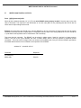
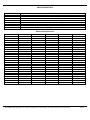
CONNECTOR PINOUTS
Screw Connector PIN
SIGNAL/SYMBOL
DESCRIPTION
1
2
3
4
PGND “G”
1–Wire Ground Pin “C”
1–Wire Input/Output Pin “S”
PWR “+”
Power Ground
Microlan™ ground
Microlan™ network I/O
Power + (unreg) 5-16 V DC
RJ-11 PINOUT
RJ11 PIN
SIGNAL
DESCRIPTION
1
2
3
4
5
6
No connection
PGND
1–Wire Input/Output Pin
1–Wire Ground Pin
No connection
PWR
No connection
Power Ground
Microlan™ network I/O
Microlan™ ground
No connection
Power + (unreg) 5-16 V DC
DB9 PINOUT
SIGNAL 9–PIN
CONNECTOR
RS232/RS485/TTL DB9 Signal
DESCRIPTION FUNCTION
NC
TXD
RXD
DTR
RTS
GND
NC
NC
NC
1
2
3
4
7
5
6
8
9
NC
Transmit Data/TXRX+/TX
Receive Data/TXRX-/RX
PWRIN1
PWRIN2
Ground
NC
NC
NC
No connection
output
input
input power (optional)
input power (optional)
(reference)
No connection
No connection
No connection
Embedded Data Systems, LLC.; 2019 Fortune Drive; Lawrenceburg, KY 40342; Phone/Fax 502-859-5490
20-33
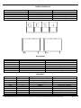
Baud Rate selection
B0
B1
Baud Rate
on
on
off
off
on
off
on
off
115 k
38.4k
19.2k
1200
PARAMETER
Supply Voltage
Supply Current
1-Wire devices
CAT-5 Cable length
Baud Rate
SYMBOL
VCC
Is
MIN
5.0
9
0
1200
TYP
12
10
-
MAX
16
12
200
2000
115K
Embedded Data Systems, LLC.; 2019 Fortune Drive; Lawrenceburg, KY 40342; Phone/Fax 502-859-5490
UNITS
Volts
mA
devices
Ft.
Baud
21-33
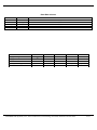
SWITCH DEFINITIONS
SWITCH #
1
2
3
4
5
6
7
8
A4
A3
A2
A1
A0
DESCRIPTION
B 0 (Baud selection bit0, see table below)
B1 (Baud selection bit1, see table below)
Checksum enable, “on” enables checksum mode.
address select bit 4 (weight of 16 when “off”)(see table below)
address select bit 3 (weight of 8 when “off”) (see table below)
address select bit 2 (weight of 4 when “off”) (see table below)
address select bit 1 (weight of 2 when “off”) (see table below)
address select bit 0 (weight of 1 when “off”) (see table below)
Address Switch Selection
A4
on
on
on
on
on
on
on
on
on
on
on
on
on
on
on
on
A3
on
on
on
on
on
on
on
on
A2
on
on
on
on
A1
on
on
A0
on
on
on
on
on
on
on
on
on
on
on
on
on
on
on
on
on
on
on
on
on
on
on
on
on
on
on
on
on
on
on
on
on
on
on
on
on
on
on
on
on
on
on
Embedded Data Systems, LLC.; 2019 Fortune Drive; Lawrenceburg, KY 40342; Phone/Fax 502-859-5490
Address
“a”
“b”
“c”
“d”
“e”
“f”
“g”
“h”
“I”
“j”
“k”
“l”
“m”
“n”
“o”
“p”
“q”
“r”
“s”
“t”
“u”
“v”
“w”
“x”
“y”
“z”
22-33
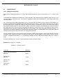
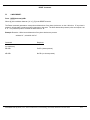
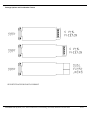
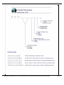
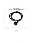
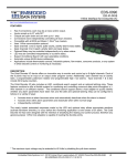
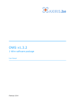
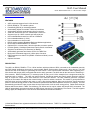
Package Options and Part Number Format
SEE NEXT PAGE FOR PART # FORMAT
Embedded Data Systems, LLC.; 2019 Fortune Drive; Lawrenceburg, KY 40342; Phone/Fax 502-859-5490
23-33
Embedded Data Systems, LLC.; 2019 Fortune Drive; Lawrenceburg, KY 40342; Phone/Fax 502-859-5490
24-33
Using EDS 1-Wire Relative Humidity Sensors With The HA5.
EDS humidity sensors contain a 12-bit analog input subsystem, a DS1820 (digital temperature sensor) and a DS2407 with
512 bytes of ROM memory. Unique device identification and calibration information is stored in the ROM memory of the
embedded DS2407. The memory also contains the address code for the DS1820 used for temperature compensation.
Many devices can be present on the 1-Wire bus of an HA5. The user must determine the ROM codes and device types of
every device on the bus. When these devices are analog sensors the calibration information must re read from each
device and used to calculate the engineering units of the parameter being sensed. Humidity sensors are DS2407 based
devices (family code 12). The ROM memory will identify the device type, provide the calibration constants and the ROM
code of the temperature sensor used to compensate the readings. The following steps are required in order to acquire
Temperature compensated Relative Humidity readings in engineering units:
Search the 1-Wire bus for Humidity sensors. Use Address command, Family search, Search or Conditional search
commands to locate ROM codes of family code 12.
Read the device ID field. Use the Read Pages command, examine bytes at locations 33-36 for device ID=”RHRH”.
Read the DS1820 ROM address. Use the Read Pages command, bytes 64-71 for ROM code of temperature sensor.
Read the calibration information. Use the Read Pages command starting at byte 79 for calibration constants. (see
table below)
Read the Current Temperature. Use the Address command with the acquired DS1820 ROM code to acquire the
temperature data.
Read the analog Humidity data. Use the “N” or “Q” command to read the analog value.
Calculate the current temperature: From the “V‟ command response; the first byte is the LSB of the 9-bit
temperature reading the second byte is the MSB. The most significant (sign) bit is duplicated into all of the bits
in upper MSB of the two-byte temperature reading. This “sign-extension” yields the 16 bit temperature readings
shown below;
Temperature
Output Binary
Output Hex
+125 deg. C
+25 deg. C
+1/2 deg. C
0 deg. C
-1/2 deg C
-25 deg. C
-55 deg. C
00000000 11111010
00000000 00110010
00000000 00000001
00000000 00000000
11111111 11111111
11111111 11001110
1111111110010010
00FA
0032
0001
0000
FFFF
FFCE
FF92
Embedded Data Systems, LLC.; 2019 Fortune Drive; Lawrenceburg, KY 40342; Phone/Fax 502-859-5490
25-33
Temperature Compensation
The humidity sensor contains a DS1820 (digital temperature sensor), the humidity sensor will need its analog reading
compensated for variations in temperature. Before or after the humidity sensor’s analog value is read, the temperature is
read from the temperature sensor (DS1820).
Use the following formula to compensate the sensor reading for the measured temperature.
ValueComp = AnalogValue * ( 1 + (CurrentTemp-TempCalib) * TempCoeff/1000000)
Where: AnalogValue - value read from the analog sensor input
CurrentTemp - value read from the attached temperature sensor (DS1820)
TempCalib - Calibrated temperature value (located in the probe's OTP)
TempCoeff - Temperature coefficient in parts per million (located in the probe's OTP)
Engineering Unit Conversion
Once the analog reading has been obtained and compensated for temperature the bus master will need to apply the
available calibration information to convert the reading to engineering units. Use the following formula to convert to
engineering units.
Scale = (Calib2Engr - Calib1Engr)/(Calib2Raw - Calib1Raw)
Offset = Calib1Engr - (Calib1Raw * scale)
EngrValue = BinaryValue * Scale + Offset
Example Below:
Scale=
Offset=
AnalogValue =
CurrentTemp =
TempCalib =
TempCoeff =
(100-0)/( (3129 (0C39h))-(717 (02CDh))=100/2114=.04146
0-(717*.04146)=-29.73
0640h , 1600 dec.
20.5 deg. C
25.0 deg. C
2150 ppm, 0866h
EngrValue = 1600 (0640h) * .04146 + (-29.73)= 36.6% Relative Humidity.
ValueComp =36.6% * ( 1 + (20.5-25.0) * 2150/1000000)=36.25% Relative Humidity (compensated)
Note: As can be seen from this example, if the temperature of the environment is relatively stable you may not need to
perform the temperature compensation.
Embedded Data Systems, LLC.; 2019 Fortune Drive; Lawrenceburg, KY 40342; Phone/Fax 502-859-5490
26-33
Search the 1-Wire bus for Humidity sensors:
Use Family Search command to find ROM code of DS2407.
Command
Response
aF12<CR>
B30000000DAAAC12<CR>
Read the device ID field.
aG,0101
1D52485248646D24D924234D355A2400000024FFFF24FFFF2439383433009E52
Humidity device ID=”RHRH” (52485248 ASCII hex)
Read the DS1820 ROM address.
Read the calibration information.
aG,0102
810000001D500D10000000F908015EB002CD3130B00C3932352EB00866FF784F
(Temperature sensor ROM code)
(calibration constants, see table below)
Read The CurrentTemp:
aA810000001D500D10<CR>
<CR> (could also use “F”,”S” or “C” commands to select)
aV <CR>
29000000FFFF214B9B<CR>
Output Binary
00000000 00101001
Output Hex
0029
Temperature
20.5 deg. C.
Read the analog Humidity data.
aAB30000000DAAAC12 <CR>
<CR> (could also use “F”,”S” or “C” commands to select)
aN00<CR>
0640 <CR>
Embedded Data Systems, LLC.; 2019 Fortune Drive; Lawrenceburg, KY 40342; Phone/Fax 502-859-5490
27-33
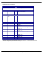
Calibration Information and Identification
Addr
Size
33
4
64
8
79
---2
---
2
---
2
1
Function
Ex
Description
In hex
DS2407 ROM Data For Humidity Sensors
** Device ID field **
Device ID
52
Used to determine type of device.
48
'RHRH' - relative humidity
52
48
** Temperature sensor ROM code **
DS1820 ROM
89
ROM address of the DS1820 attached.
Addr
00
00
00
0F
0A
69
10
** Calibration Table **
Calib1Engr*
B0
First calibration in engineering units
Example: 0
Calib1Raw
02
First calibration in raw binary units
CD
Example: 717
Calib2Engr*
31
Second calibration in engineering units
30
B0
Example: 100
Calib2Raw
0C
Second calibration in raw binary units
39
Example: 3129
TempCalib*
31
Calibration Temperature for compensation
39
2E
37
B3
Example: 19.73
TempCoeff
08
Temperature Coefficient for compensation
66
Example: 2150
Table Terminator
FF
Terminates the calibration table
* Designates a Real Number field. Real Number fields are ASCII strings with no null terminator but with the last
characters most significant byte set to indicate end of string.
Embedded Data Systems, LLC.; 2019 Fortune Drive; Lawrenceburg, KY 40342; Phone/Fax 502-859-5490
28-33
Gathering Data From DS1820/1920s and DS2406/2407s Using Multiple HA5s
Overview
This document describes how to gather information from DS1820/1920s and DS2406/2407s using multiple HA5s through
an RS485 network. Please refer to the HA5 specification for more information.
Checksums
It is highly recommended that Checksums be enabled when using HA5s in a multi-drop mode. For initial development,
Checksum mode is not required. The checksum incorporates all characters in a command or response but does not
include the <CR>. Checksum must be enabled on the HA5. If Checksum mode is not enabled on the HA5, the HA5 just
ignores the checksum in the command but does not send the checksum in the response.
In the examples, Checksums are italicized.
Polling Methods
There are two methods to poll the devices attached on the HA5s. The first method uses the search command to select
the device. This method allows you to be flexible about the number of devices attached to the network. The second
method uses the search commands to obtain the serial numbers of the devices attached to the HA5. The serial numbers
are stored then used to address each device one at a time. This method is useful when the number of devices is not
expected to change.
Finding HA5s
If an HA5 is not present or the command is not received because of communication errors, no response may be given.
The Host should be prepared to time-out if no response is given. The HA5 will respond with an error code (BEL, hex 07)
followed by a <CR> if an error is encountered while attempting to execute the given command.
To find the HA5s attached, try sending the search command to all 26 potential addresses. The following illustrates:
Commands
Reponses
aS,0141<CR>
7F0000000836A41044<CR>
bS,0142<CR>
A00000000B14E71045<CR>
cS,0143<CR>
nothing
(wait for timeout)
nothing
(wait for timeout)
….
zS,015A<CR>
Other commands can be used to determine if the HA5 is there like the Reset Command.
Embedded Data Systems, LLC.; 2019 Fortune Drive; Lawrenceburg, KY 40342; Phone/Fax 502-859-5490
29-33
Family Codes
DS1820/1920 have family code of 10hex and DS2406/2407 have family code of 12hex.
Polling Method 1
This method uses the search command to select the device. The following illustrates:
Commands
aS,0141<CR>
Send command to device
Reponses
7F0000000836A41044<CR>
aSB4<CR>
A00000000B14E71045<CR>
Send command to device
….
aSB4<CR>
<CR>
( no more devices )
<start again with another HA5>
Polling Method 2
This method uses the search commands to obtain the serial numbers of the devices attached to the HA5. The serial
numbers are stored and then used to address each device one at a time. This method is useful when the number of
devices is not expected to change. The following illustrates:
Commands
aS,FF6C<CR>
Reponses
7F0000000836A41044<CR>
A00000000B14E71045<CR>
0600000001C8BE124C<CR>
<CR>
<store received serial numbers and HA5 address>
…
qS,FF7C<CR> (last HA5)
880000000836A41037<CR>
EA0000001C8BE123C<CR>
<CR>
<store received serial numbers and HA5 address>
aA7F0000000836A410E6<CR>
7F0000000836A41044<CR>
Send command to device
… continue for each address received
qA880000000836A410E9<CR>
880000000836A41037<CR>
Send command to device
Embedded Data Systems, LLC.; 2019 Fortune Drive; Lawrenceburg, KY 40342; Phone/Fax 502-859-5490
30-33
Gathering Temperature Data (DS1820)
For DS1820s that are powered parasitically, use the V command to obtain the temperature data. The V command can be
used with externally powered DS1820s except that the DS1820 can convert the temperature in 120 ms; the V command
takes 500 ms. For externally powered situations, use the W and J commands to gather the data in the most timely and
efficient manner. The following illustrates how to gather temperature data using the V command:
Commands
Reponses
< use the S or A commands to select device >
qVC7<CR>
29000000FFFF214B9BF7<CR>
The response is a 9-byte string, 8 scratchpad bytes and a CRC. The temperature data is contained in the first two bytes
of the 9-byte scratchpad plus CRC data block returned. The data is as follows:
TEMP =
C_REMAIN =
C_CNT =
CRC =
0029h (41 dec)
21h (33 dec)
4Bh (75 dec)
33h (51 dec)
Temperature = Temp / 2
bytes 1 & 2 (where byte 1 is LSB)
byte 7
byte 8
byte 9
(in degrees C)
For higher resolution use the following equation:
float TValue = (float)((short)(Temp & 0xFFFE) / 2);
if (Cnt_C == 0)
error
Temperature = TValue - 0.25 + (Cnt_C - Cnt_Remain)/Cnt_C );
For ultimate integrity of the data the CRC should be used to verify the contents of the data. See the section Calculating
CRC-16 and CRC-8 for information on calculating CRC-8s. For more information please consult the specification for the
DS1820.
Gathering I/O from the DS2406
Use the D and the DR command to read the I/O states of the DS2406. The DS2406 has an activity latch that can be reset
with the DR command. The following illustrates reading the I/O data:
Commands
aDA5<CR>
Reponses
7F7D<CR>
<is activity latch set? Yes the send DR command to reset latch>
aDRF7<CR>
4F7A<CR>
The data is as follows:
Output A
Output B
Current Sensed Input A
Current Sensed Input B
ActivityLatch A
ActivityLatch B
bit 1
bit 2
bit 3
bit 4
bit 5
bit 6
Embedded Data Systems, LLC.; 2019 Fortune Drive; Lawrenceburg, KY 40342; Phone/Fax 502-859-5490
31-33
The D and DR commands do not check the CRC16 error check that is returned from the DS2406. The response of the D
or DR commmands is vulnerable to errors on the 1-Wire bus. If you need error checking, you can use the block
commands to communicate directly with the DS2406. You will then need to process the CRC16 error check yourself.
The following illustrates using the block command to obtain the I/O data:
Commands
aW07F55DFFFFFFFFFF33<CR>
Reponses
F55DFF7FFF300632<CR>
<reset latch and read inputs>
aW07F5DDFFFFFFFFFF33<CR>
F5DDFF6FFF140662<CR>
The data is as follows:
Channel Info Byte
OutputA
OutputB
SensedA
SensedB
LatchedA
LatchedB
No Channels
Supply
CRC16
byte 3
bit 0
bit 1
bit 2
bit 3
bit 4
bit 5
bit 6
bit 7
ex: 7Fhex
1
1
1
1
1
1
1
0
byte 5
ex. 0630hex
For more information please consult the specification for the DS2406/2407.
Setting the Outputs of the DS2406
Use the E command to set the outputs of the DS2406. The HA5 error checks the communications; if there is an error in
the communications HA5 will not attempt to set the output.
The follow is an example of setting the output:
Commands
<set outputs to 1>
aE6612<CR>
<set outputs to 0>
aE060C<CR>
aE060C<CR>
Reponses
666C<CR.>
0666<CR>
<BEL>
The outputs are located in bit 5 for A and bit 6 for B. Consult the Dallas DS2407 specification for the meaning of the other
bits in the Status Ram location 7.
Embedded Data Systems, LLC.; 2019 Fortune Drive; Lawrenceburg, KY 40342; Phone/Fax 502-859-5490
32-33
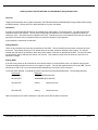
Calculating CRC-16 and CRC-8
CRC-16
Here is a Pascal routine to calculate CRC16:
Var
CRC16 : Word;
{----------------------------------------------------------------------------}
{ This procedure accumulates the CRC16 CRC of the data X in the
global variable CRC16.
}
Procedure TMainForm.DoCRC16(X: Byte);
Var
I : Byte;
F : Boolean;
Begin
For I := 1 to 8 do Begin
F := Odd(X xor CRC16);
CRC16 := CRC16 shr 1;
X := X shr 1;
If F then CRC16 := CRC16 xor $A001;
End;
End;
CRC-8
Here is a pascal routine to calculate CRC8:
Var
CRC8 : smallint;
{ This procedure calculates the cumulative Dallas Semiconductor
one-wire CRC8 of all bytes passed to it. The result accumulates
in the global variable CRC8.
}
Procedure TMainForm.DoCRC8(X: Byte);
Const
Table : Array[0..255] of Byte = (
0, 94,188,226, 97, 63,221,131,194,156,126, 32,163,253, 31, 65,
157,195, 33,127,252,162, 64, 30, 95, 1,227,189, 62, 96,130,220,
35,125,159,193, 66, 28,254,160,225,191, 93, 3,128,222, 60, 98,
190,224, 2, 92,223,129, 99, 61,124, 34,192,158, 29, 67,161,255,
70, 24,250,164, 39,121,155,197,132,218, 56,102,229,187, 89, 7,
219,133,103, 57,186,228, 6, 88, 25, 71,165,251,120, 38,196,154,
101, 59,217,135, 4, 90,184,230,167,249, 27, 69,198,152,122, 36,
248,166, 68, 26,153,199, 37,123, 58,100,134,216, 91, 5,231,185,
140,210, 48,110,237,179, 81, 15, 78, 16,242,172, 47,113,147,205,
17, 79,173,243,112, 46,204,146,211,141,111, 49,178,236, 14, 80,
175,241, 19, 77,206,144,114, 44,109, 51,209,143, 12, 82,176,238,
50,108,142,208, 83, 13,239,177,240,174, 76, 18,145,207, 45,115,
202,148,118, 40,171,245, 23, 73, 8, 86,180,234,105, 55,213,139,
87, 9,235,181, 54,104,138,212,149,203, 41,119,244,170, 72, 22,
233,183, 85, 11,136,214, 52,106, 43,117,151,201, 74, 20,246,168,
116, 42,200,150, 21, 75,169,247,182,232, 10, 84,215,137,107, 53);
Begin
CRC8 := Table[CRC8 xor X];
End;
Embedded Data Systems, LLC.; 2019 Fortune Drive; Lawrenceburg, KY 40342; Phone/Fax 502-859-5490
33-33