1
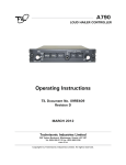
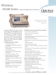
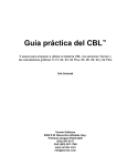
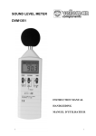
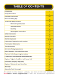
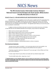
INSTALLATION & USER’S GUIDE
AIRBORNE LOUDSPEAKER SYSTEMS
PSAIR12
PSAIR12+1
PSAIR22
PSAIR42
Power Sonix, Inc.
122 S. Church St., Martinsburg, WV 25401
304-267-7560; Fax 304-268-8691
www.powersonix.com
TABLE OF CONTENTS
I.
Overview Of Aero Voice Public Address Systems
Page 1
Installation Options
II.
Installation Quick Start & Checklist
Page 3
Standard Cable Connections
Power For The Aero Voice System
AC Power From Aircraft
DC Power From Aircraft Batteries
DC Power From Power Sonix 28 V auxiliary battery pack
Audio Controller/Remote Control Unit
III.
Mounting The Amplified Speaker(s)
Page 6
PSAIR12
PSAIR12-1
PSAIR22
PSAIR42
IV.
Using the Aero Voice System
Page 10
Using the Power Sonix Remote Control Unit
Interfacing With Cockpit Audio Controllers
Live Microphone
Pre-Recorded Messages, Tape/Digital Input
Standard Sirens
Custom Sirens/Sounds
V.
Maintenance
Page 13
Routine audio testing
Battery maintenance & charging
VI.
Technical Specifications
Page 17
VII.
Limited 2-Year Warranty
RMAs
Power Sonix Support
Page 18
VIII.
Your Dealer/Outfitter Info:
____________________________________________________
Dealer Sales Contact
Phone
____________________________________________________
Dealer Customer Service Contact
Phone
____________________________________________________
Outfitter/Installation Service Contact
Phone
____________________________________________________
304-267-7560
Power Sonix Factory Support/RMAs Contact
© 2003 Power Sonix, Inc. All rights reserved.
Page 1
I.
Overview Of Aero Voice Public Address Systems
Congratulations on your purchase of a Power Sonix public address system. Your
aircraft is about to be equipped with the best performing airborne speech
projection system in the world today. No other system is as light, as compact, as
intelligible, as powerful or as economical as Power Sonix.
The Power Sonix Aero Voice Public Address Systems are very modular in
nature and very easy to understand. The systems described herein are the 300watt PSAIR12, the 600-watt PSAIR12+1, the 600-watt PSAIR22 and the 1200watt PSAIR42.
The Amplified Speaker Array: The core audio components are the horns (bells),
the speaker drivers that force the sound through the horns, and the high
efficiency Class D amplifier that delivers the audio signal to the drivers. These
components are all enclosed in one lightweight, rugged aluminum assembly we
call an Amplified Speaker which provides excellent heat sinking. The amplified
speaker array is mounted to the aircraft in one of two ways. It can be recessed
into the cavity of the fuselage, space permitting. It can also be mounted with
metal brackets attached to the undercarriage of the aircraft.
Installation Considerations: The first thing that must be determined is where you
will place the speaker array on your specific aircraft. Power Sonix recommends
that the system be mounted in such a way as to project sound down and away
from the aircraft at an angle that is consistent with the aircraft’s mission
requirements. At an angle of 45 degrees with the vertical, the peak intensity of
the sound beam will hit the ground at an distance from the aircraft that is equal
to the altitude of the aircraft
(see illustration 1 right).
Reducing the angle,
reduces the distance that
the peak sound intensity
will be experienced by
those on the ground,
away from the aircraft.
The distance out from the
aircraft of peak intensity is
the product of the tangent
of the angle times the
expected height of the
aircraft during broadcast.
Illustration 1- 45° angle
down and away from aircraft
© 2003 Power Sonix, Inc. All rights reserved.
Page 2
Once placement has been determined, the next consideration is what will
power the PA system. Power can come from DC power supplies already on the
aircraft, or a Power Sonix 28V auxiliary battery pack. Stand alone battery
packs have limited power and must be recharged. Consult with your dealer and
your maintenance chief to determine which is best for your needs.
A 45° angle enables the pilot and/or observer to maintain visual contact with
the intended audience from a safe hovering position. Don’t be concerned with
being too far from your audience. Power Sonix systems have great range. If
you are close, you can always reduce the volume.
The third major consideration is interfacing the audio signal sources
with the Amplified Speaker Assembly. You can use the cockpit headphone mic
to deliver speech through the cockpit audio controller to the amplified speaker
array. This requires that the cockpit audio controllers have an audio output jack
for a PA system (many commercial controllers like Technisonics, Garmin and
NAT do). See the operating manual of your controller to see how to integrate
your existing equipment with Power Sonix PA Systems. Our engineering dept.
is always available to help answer questions regarding this procedure….please
feel free to call to expedite your installation.
Instead of the cockpit headphones, you can alternatively use a separate noise
cancelling microphone (Power Sonix part # PSMIC) and the Power Sonix
Remote Control Unit (PSRCU). The RCU is required in any instance where the
existing cockpit audio controller does not support a public address system. In
that case, it is the audio controller for the PA and has its own on/off switch.
The advantage to having the RCU, in addition to a supporting cockpit audio
controller, is the convenience to do things quickly and easily in the air
including; 1.) having someone without a headset speak into the system with a
hand-held mic, 2.) the ability to plug a cassette tape, CD player or DVD player
with pre-recorded messages/sounds into the RCU which delivers the digital
signal to the amplified speaker array. If you intend to do these things with your
existing audio controller, make sure that it has the necessary wiring
interconnects available and consult your equipment user’s manual.
The finish on the Remote Control Unit is anodized black. The speaker
assemblies come standard in a powder-coated white or olive drab finish.
© 2003 Power Sonix, Inc. All rights reserved.
Page 3
II.
Installation Quick Start
Standard Cable Connections
There are only a few connections that have to be made to make your
Power Sonix system operational. All the wiring inside the amplified speaker
array is factory installed and tested. There is no need to access the internal
assembly of the amplified speaker array.
Once the speaker array mounting position is determined, measurements of
the distance from the amplified speaker to the power source and to the
audio controller (either the cockpit audio controller or the Power Sonix
Remote Control Unit) are made. Standard cables are provided in 10' and
15' lengths and should meet most requirements. If standard cables are not
long enough, either Power Somnix or your aircraft maintenance facility can
make custom cables.
Illustration 2 depicts the PSAIR cabling requirements. Illustration 3 below
shows a diagram of the the cable used to connect the amplified speaker
array to either the cockpit audio controller or the Power Sonix Remote
Control Unit (PSRCU).
The amplified speaker array
(PSAIR42 shown), connects to
a power supply and to an
audio controller.
Power is usually supplied from
existing aircraft batteries (must be
rated 28v) or an auxiliary battery like
the Power Sonix PSBAT28 shown left.
The mic in the cockpit headset
can be used if connecting to the
cockpit audio controller. A
separate mic is used when
connecting to the Power Sonix
remote control (PSRCU).
The loudspeaker system is
controlled by either the cockpit
audio controller (if capable), or by
the Power Sonix Remote Control
Unit (PSRCU) shown to the right.
AC Battery Charger
(PSACDC) plugs directly into
“Power-In” connector on 28V
battery (PSBAT28) during
routine maintenance.
The REC input connection
allows prerecorded message
to be played from cassettes
or CD players.
Illustration 2 - Basic System Connections
© 2003 Power Sonix, Inc. All rights reserved.
Page 4
Illustration 3 - Audio Remote Control Cable PSCBL-RCU
Used when connecting PSAIR amplified speaker array to the
Power Sonix Remote Control Unit, PSRCU
Illustration 4 - Signal Cable PSCBL-SIG
Used to connect PSAIR amplified speaker arrays
to the Cockpit Audio Controller
Illustration 5 - Auxilary Speaker cable PSCBL-AUX
Used to connect audio from the master PSAIR12 amplified speaker array
to the Auxilary +1 Speaker assembly
The PSAIR12+1 has an additional cabling requirement. An audio cable
connects the amplified speaker and the second speaker. The second
speaker can be mounted directly next to the amplified speaker or it can be
mounted on the other side of the undercarriage to project sound in a
completely different direction/area.
On the rear panel of each PSAIR amplified speaker
array, there is an Activation Switch (pull up to toggle).
In the “ON” position, the system is ready to be
controlled by the cockpit audio controller. In the “OFF”
position, the unit is controlled by the Power Sonix
Remote Control Unit (PSRCU). Additionally, when
not using the PSRCU, a low impedance source (150
ohm, milli-volt level signal) can be applied to the
pre-amp input. A 5mv rms signal will produce full
power rating at the speaker output.
© 2003 Power Sonix, Inc. All rights reserved.
Illustration 5 Activation Switch
Page 5
Power Connections For The Aero Voice System
The source power source MUST be 24-32 VDC (i,e, nominal 28 V aircraft
supply). NOTE: THESE SYSTEMS ARE NOT DESIGNED TO OPERATE
WITH MORE THAN 32 VOLTS.
Using AIRCRAFT DC POWER - This requires Power Sonix power cable
PSCBL-DC in the length appropriate for your aircraft. No power supply
converter is needed when utilizing DC power.
Using AUXILIARY BATTERY POWER - This requires a Power Sonix 28 Volt
NiCad battery pack (PSBAT28 or PSBAT28SCU) and Power Sonix power
cable PSCBL-BAT in the length appropriate for your aircraft.
Please consult with your dealer, outfitter and maintenance crew chief to
determine the power configuration that best meets your needs on your
aircraft. The load of other systems that could ever be used simultaneously
with the PA must be taken into account when considering using existing AC
or DC power supplies on board your aircraft. Please contact Power Sonix
Engineering. Dept. for any questions regarding any installation issues.
Illustration 6B - Power Cable Connections For PSAIR12 & PSAIR12+1
© 2003 Power Sonix, Inc. All rights reserved.
Page 6
Illustration 6B - Power Cable Connections For PSAIR22 & PSAIR42
III.
Mounting Your Aero Voice Public Address Systems
General Considerations
Your aircraft is unique. The systems and equipment installed inside and
outside the fuselage are likely different from other aircraft, even within your
own fleet. One user may want the system attached to the fuselage, one may
want it it attached to the struts, another may want it recessed into the
fuselage. A searchlight may already be a in position you’d like to use. The
size of strut bars varies widely from lightweight to heavyweight helicopters.
Because there are so many variables, brackets must be fabricated to meet the
specific needs of you aircraft.
Your Power Sonix dealer and your helicopter outfitter will work with you to
determine exactly where the system should go on your aircraft and will
fabricate the metalwork to form a bracket for permanent installation. Power
Sonix provides the technical specifications for the measurements of the
mounting hard points on each of our amplified speaker arrays. With this
information, the service engineers are able to devise a bracket to meet
your needs.
© 2003 Power Sonix, Inc. All rights reserved.
Page 7
Mounting Hard Points
PSAIR12 AND PSAIR12+1
The PSAIR 12 is a single bell system and our smallest Airborne model. The
small footprint offers installers great flexibility in determining the placement
on the airframe or fuselage. Illustration 6 below shows the location of the 832NC threaded hard points, 4 on each side of the PSAIR12.
These measurements also apply to the auxiliary speaker assembly of a
PSAIR12+1 and for attaching a bracket to the short side of the PSAIR22.
6.500"
2.500"
4.500"
6.750"
PSAIR12 OR PSAIR12+1
Hard Points
2.000"
3.500"
8-32 NC Hard Points
4 On Each Side
2.000"
3.500"
2.000"
7.625"
Illustration 7 - Mounting Hard Points For PSAIR12 or PSAIR12+1
Illustration 8 - Mounting Hard
Points For PSAIR22
9.50"
3.000"
3.000"
9.500"
6.500"
1.750"
1.250"
1.750"
9.750"
Eight 8-32 NC
Hard Points on each side
of speaker assembly
1.750"
4.500"
1.750"
1.500"
1.500"
1.500"
4.750"
7.625"
© 2003 Power Sonix, Inc. All rights reserved.
8.250"
PSAIR22
Hard Points
1.250"
The PSAIR22 is a 2-bell system
that has 600 watts of power. The
hard points on the enclosure are
located on the short sides of the
enclosure. This enable the
assembly to be mounted and
oriented in such a way as to
provide a horizontally broader
area of sound dispersion. The
eight hard points ensure a solid
and stable attchment to the
mounting bracket and aircraft.
1.250"
PSAIR22
1.00"
Page 8
PSAIR42
PSAIR42
Hard Points
15.000"
Two 1/2 - 13 NC
Hard Points on each side
of speaker assembly
4.344"
15.250"
6.312
4.344"
The PSAIR42 is a 4- bell system and the most powerful of our standard
Airborne models. This system can be attached to airframe, struts or recessed
into the fuselage. Illustration 6 below shows the location of the 1/2"-13NC
threaded mounting hard points on the side of the PSAIR42. The holes are
6.312" apart on center. From the center of the hard point, there is a distance
of 5.00" to the outer edge of the assembly back cover.
5.000"
2.50"
7.625"
Illustration 9 - Mounting Hard Points For Mounting PSAIR42
© 2003 Power Sonix, Inc. All rights reserved.
Page 9
Angle of Voice/Sound Projection
If most communications are made from a level hovering position relatively
close to the target audience, a 45° mounting position down and away from
the fuselage is recommended to direct the sound beam to an area outside
the rotor blast. Speaker angles may need to be adjusted based on mission
objectives.
The sound beam is directional. The beam’s intensity falls off to 50% at 30°
degrees to either side of the direct line of sight of the center beam
Using One PA System For Multiple Helicopters
If you have multiple aircraft that you want to use a single Power Sonix
loudspeaker system on, you can do it. First, a permanent bracket would be
installed on each helicopter. This may require variations of the bracket.
However, the part of the bracket that mounts to the amplified speaker
assembly hard points would be identical on all brackets. You would also
need to pre-wire each helicopter with the power and audio remote control
cables needed for each aircraft. When not in use, they would need to be
secured.
Once each aircraft is outfitted, the amplified speaker array can be moved
from one aircraft to another. It is important to note that an FAA field test
(Form 337) is required for each aircraft that you are modifying since this
approval procedure is serial number specific. (See NOTE above.)
FAA Field Inspection
Once installed, an FAA Form 337 Field Test must be conducted to get your
modification approved. There is no cost from the FAA for this test. After you
schedule the inspection with your nearest FAA Field Office, you just have to
make the aircraft and a pilot available. This is standard procedure and any
FAA licensed maintenance or overhaul facility will take care of this for you.
(Note: Military and State and Local Government Law Enforcement agencies
may not be subject to the N Classification modification requirements of the
FAA. However, it is always a good practice to thoroughly test the aircraft after
any major modification, including the addition of externally mounted
loudspeakers, searchlights, cameras etc.).
© 2003 Power Sonix, Inc. All rights reserved.
Page 10
IV.
Using the Power Sonix Aero Voice System
Operating the voice Amplifier system is relatively simple. However, certain
techniques, some of which will be gained by experience, should be developed
to obtain the most favorable results. The system possesses the capability of
high quality voice transmission over long distances and for long periods of
time. However, effective utilization of these features depends, to a great extent,
upon proper operating procedures.
To successfully project the voice over long distances, it is necessary to develop
a microphone technique different from the normal conversational manner. Talk
clearly and distinctly, separating each word with noticeable pauses. Keep the
voice volume high with the top of the microphone touching the upper lip so that
the speech is as close to the microphone as possible. A normal (medium
pitched) voice is more intelligible and carries farther than a bass voice.
Microphone Options And Operation
Users may utilize an existing cockpit headset microphone connected to a
cockpit audio controller provided that the controller has appropriate connectors
to receive the cable from the Power Sonix amplified speaker assembly .
Alternatively, users can employ the Power Sonix/Shure, noise-cancelling
microphone (PSMIC) by connecting it to either a mic jack on the cockpit audio
controller or to the mic jack on the Power Sonix Remote Control Unit (PSRCU).
On the PSMIC, the "Gain" control is adjusted clockwise from OFF. If troubled
with feedback it may be necessary to reduce the input "Gain" control or
preferably, improve the sound shielding of the microphone position. This can be
done by closing windows and eliminating a direct audio air medium back to the
microphone from the speakers.
© 2003 Power Sonix, Inc. All rights reserved.
Page 11
Remote Control Unit
The Power Sonix Remote Control Unit (PSRCU) can independently control all
aspects of the loudspeaker system. This component is required if your cockpit
audio controller does not have the capacity to
interface with the Aero Voice system and its
connecting cables. Please contact Power Sonix
([email protected]) to determine the
necessary wiring connections to use a specific
cockpit controller. We will need a wiring
diagram of the controller output connector and
its electrical specifications to interface the two
systems.
The Remote has an audio input jack for a
microphone and one for an audio recording
devise such as a tape cassette recorder, CD
player or DVD player. These devises can deliver
standardized and studio quality pre-recorded
messages to the Aero Voice loudspeakers. The
large connector on top of the Remote is used to
connect it to the amplified speaker array (using
cable PSCBL-RCU).
Power Sonix systems are not intended to play hi-fidelity music. If the recorded
sound is music, it is advisable to operate at a reduced "Gain" control setting.
Failure to reduce the gain setting may cause excessive power to be dissipated
in the speaker units and result in
failure of the speaker voice coils due
PIN
FUNCTION
to overheating.
The red Push-To-Test (PTT) power
light will show that DC power is
connected when depressed. It is
also an indicator that the system is
on when the power toggle switch is
turned on. The ten element bar
graph shows the level of power
being delivered to the speakers from
the amplifier. It also has one
element lit when no signal is applied
and serves as a secondary power
on indicator.
© 2003 Power Sonix, Inc. All rights reserved.
A
B
C
D
E
F
G
SWITCHED POWER
GROUND
+ VOLTAGE
- SIGNAL
+ SIGNAL
RELAY
METER SIG. (0-5V)
Remote Control Unit PSRCU
PIN Function Chart
Page 12
The "Gain" dial indicates the power or volume that the speakers are putting
out. For safety reasons, it is best to keep the "Gain" in the "Off" position until
you are ready to begin your broadcast. If any feedback occurs, it may be
necessary to reduce the input "Gain" control or preferably, improve the
sound shielding of the microphone.
When a siren sound is needed, a separate siren switch is pushed to activate
the sound. Press the switch for the sound (siren wail or trill) you wish to
broadcast. Pressing the switch while the siren is broadcasting will turn the
siren OFF again. Custom siren sounds can be permanently encoded onto a
chip inside the Remote Control Unit for a moderate feel. Each custom sound
would replace one of the two standard sirens factory installed. This requires
sending the PSRCU unit back to Power Sonix for modification along with a
digital recording of the sound you wish to use and, if applicable, a decision
on which of the existing sirens you want to replace.
AC Battery Charger
(PSACCHARGE)
© 2003 Power Sonix, Inc. All rights reserved.
28V Battery with State of
Charge Unit (PSBAT28SCU)
Page 13
Maintenance
Routine testing of the loudspeaker equipment should be incorporated into the
maintenance or flight-ready checklist. Simple troubleshooting can be
conducted in the hanger. Power Sonix Tech Support is always available via
phone to assist in the installation and troubleshooting. Any major issues with
your equipment would require an RMA for factory servicing.
Amplifier Checks - When normal operation is impaired the following
possibilities should be checked:
a. Press the “Press To Test” (PTT) light to make sure power is available
(if using the Power Sonix Remote Control Unit PSRCU)
b. Check the input Polarity of the DC supply. Make sure sufficient
voltage is available, and that excessive voltage is not applied;
(no greater than 32 volts DC)
c. Check any cable for shorts or opens. DC resistance on the drivers is
approx 2.5 ohms.
d. Battery may not be properly connected. The PTT light does not
indicate until pressed.
d. Power Switch off. PTT light does not indicate until pressed.
e. No DC power to Remote Control Unit. PTT light does not indicate
normally or when pressed.
f. Make sure the signal source is not shorted or connected to any
noise source.
g. The Amplifier may be faulty. This will require factory maintenance.
The amplifier will automatically reset when reapplying power
after a fault is found.
Power Supply Checks - The battery voltage should measure between 24 and
32 volts unloaded and l/2 to l volt lower under load. Check the proper polarity.
Loudspeaker And Cable Checks - Testing of loudspeakers and cables may, to
some extent, be done visually. All connections should be free from dirt,
moisture and open or shorted conditions. All receptacle threads should be
thoroughly engaged. A continuity meter may be used to establish the state
and correctness of wiring. An ohmmeter touched across the loudspeaker
inputs should cause an audible click sound.
Precautions In Maintenance - To avoid serious damage to system components
while undergoing troubleshooting or testing, please read these warnings
carefully before initiating test procedures.
© 2003 Power Sonix, Inc. All rights reserved.
Page 14
CAUTION: Always pre-test the amplified speaker with 20 volts DC supply
voltage when its condition is doubtful. This precaution will minimize the
danger to expensive components.
CAUTION: Do not operate the system from an inadequate power supply or a
shop supply, giving rise to high voltage transients.
CAUTION: Careless poking around with a screwdriver in a live circuit can
cause extensive damage. Even momentary large currents or voltages
through power FETs can permanently damage the unit.
CAUTION: A grounded test probe from a AC powered meter or Scope
placed across the output will short the output to ground and trigger the
shutdown circuitry. All test equipment should be isolated from ground
potential.
Amplified Speaker Maintenance - The amplified speaker should be kept
clean and free from exposure to static charge accumulation and debris.
There are no serviceable procedures to be used in repairing the Class D
amplifier inside the assembly.
CAUTION: Tampering with the amplifier board itself will void your warranty.
Field access to the amplified speaker assembly can only be made with
factory authorization. Unauthorized access voids the warranty.
Mounting Bracket Maintenance - Consult your dealer or service provider
who installed your Power Sonix equipment regarding any maintenance
procedures pertaining to the mounting bracketry.
Specifications for 600-watt, Class D Amplifiers and Pre-Amp
Specification
Distance @ 70db
SPL @ 1m
Number of Speakers
Power Output
Pre-Amp
Frequency Response
Harmonic Distortion
Sensitivity
DC Voltage Range
Peak Current Shutdown
PSAIR12
PSAIR12+1
PSAIR22
PSAIR42
.75 miles
.75 miles
1.25 miles
2.0 miles
145 dB
145 dB/pr
148 dB
151dB
1
2 Separate
2
4
300W RMS 600W RMS
600W RMS 1200W RMS
150 Ohm Input Impedance (All Systems)
400 to 4500 Hertz (All Systems)
1% (All Systems)
1 Volt RMS @ 1 KHertz (All Systems)
24-32 Volts DC
35 Amperes RMS
© 2003 Power Sonix, Inc. All rights reserved.
Page 15
Speaker Driver Maintenance - No maintenance of the speaker driver is
required. Should a driver fail while under warranty, please return it to Power
Sonix for replacement. If out of warranty, please call Power Sonix to
purchase a new driver.
Speaker Driver Replacement
A loudspeaker driver may fail due to several causes.
(1) The coil or its terminals may short to the mounting and cause the
amplifier to cut off. This is apparent (once the leads of the suspected driver
are separated from other drivers of the speaker assembly) by a continuity
test from a lead to the chassis ground.
(2) A voice coil short (not likely) showing zero ohms between voice
coil leads will also cause the amplifier to cut off.
(3) A voice coil open-circuit (more likely) will show with an ohmmeter
check between leads. No sound will result when the ohmmeter is applied.
(4) A noisy driver results when the voice coil rubs against the
magnetic gap. Noise can best be localized to a single driver unit by
connecting each unit singly and energizing each with the amplifier output.
To access the drivers:
1.) Make sure your are adequately grounded.
2.) Unscrew the lid to the rear enclosure
2.) Remove the re-entrant tip from the front of the horn section of the
speaker (unscrew counter-clockwise).
3.) The faulty driver is then freed by removing the four 1/4 - 20
mounting screws now exposed.
Check each driver for a short or an “open”. A short is evidenced by less
than 1 ohm resistance and an “open” by any resistance over 3 ohms. The
correct reading should be approximately 2.5 ohms. Shorts from the wiring to
the chassis can be checked with a ohm meter, one lead on the chassis and
the other touching the separated output lines connected to the speaker
drivers lines which should not show a zero ohm resistance to the case.
There is no need to perform impedance tests.
Install the replacement driver by accessing the enclosure using the above
procedure. Connect the leads to the terminals at the rear. Observe the color
code to preserve the speaker polarity.
IMPORTANT - RED TO #1 TERMINAL, BLACK TO #2 TERMINAL
© 2003 Power Sonix, Inc. All rights reserved.
Page 16
Resetting Protective Circuit
The Power Sonix 600 Watt Class D amplifier is designed with self-protecting
circuitry to interrupt the operation whenever unusual conditions exist which
might endanger the amplifier components.
Such a condition might be an excessive load current or an output short. Once
the protective circuit is activated, the flow of power is stopped in the affected
channel and no further operation is possible without corrective action. If the
trouble was due to a temporary or transitory cause, operation may be
resumed by simply turning the power switch OFF, wait 5 seconds to allow the
internal circuitry to reset, then turn back to ON.
Summary of Care And Precautions
The Power FETs of this system are subject to damage when exposed to
excessive heat, voltage, and current for even short periods of time. The design
incorporates a protective circuit for each channel which disables the amplifier,
or channel affected, when safe operating currents are exceeded.
Operation of a protective circuit is indicated by the extinguishing of the
amplifier power lamp. The protective circuits are adequate in most instances;
however, they are also subject to damage when extreme or sustained stresses
are allowed to exist. Careful monitoring is therefore necessary when operating
under unusual environmental extremes.
Precautions should be taken to maintain temperature within recommended
limits (see Par. 4, Section l). Other damaging conditions are: excessive battery
charging voltage; short circuits within the system; transmission of compressed,
high level music resulting in continuous high-level power generation.
© 2003 Power Sonix, Inc. All rights reserved.
Page 17
Technical Specifications:
1. SUPPLY VOLTAGE: These integrated systems are designed to operate on a
nominal 28 volt DC aircraft voltage. Operation at higher voltages may cause
speaker damage as they are designed to deliver 150 watts each at the 28 volt
DC rating. Higher voltage operation will therefore cause overheating and
possible speaker failure. Do not operate Power Sonix loudspeakers at voltages
over 32 Volts DC.
2. FREQUENCY RESPONSE: The amplifier response is flat within 3 dB over
the frequency range of 400 to 4500 HZ. The amplifier filters input signals with
4th order low and high pass filters. This band pass window is designed for
maximum voice intelligibility.
3. HARMONIC DISTORTION: The THD is less than 1% at a frequency of 1 KHz
at low input signal levels.
4. SENSITIVITY: The amplifier will deliver 600 watts of power into a resistive 1
ohm load at a 28 volt DC supply when a signal of 1 volt rms @ 1 KHz is applied
to the signal input, pins D and E on the remote connector.
5. POWER OUTPUT/SPL: The amplifier output power is a function of the
number of speaker drivers used. The maximum power output is 600 watts,
capable of driving 4 speaker drivers rated at 150 watts each. The SPL rating at
600 watts of power is 148 dB at 1 meter, sufficient to project voice signals in
excess of 1 mile in a specific direction from the air to the ground.
6. CURRENT DRAW: When delivering the full 600 watts to the speaker load,
the amplifier will draw approximately 24 amps DC. Each 150 watt speaker driver
uses 6 amps max for operation at 28 volts DC. The protective circuit is designed
to shut down operation if the rms current exceeds 35 amps DC. If shut down
occurs, turn off the power to the unit, wait 5 seconds, re-apply power.
7. TEMPERATURE RANGE: The amplifier will operate between -40 to 150F
ambient (-40 to 65 C).
8. ALTITUDE: The systems are capable of operating at any altitude up to 15,000
feet.
9. PROTECTIVE CIRCUIT: As stated above, the systems are protected on the
high voltage side against shorts. If the rms current exceeds 35 amps, the
amplifier will turn off to protect itself. To reset the amplifier, turn it off for several
seconds and then re-apply power.
© 2003 Power Sonix, Inc. All rights reserved.
Page 18
Warranty
Power Sonix, Inc. offers a Two-Year Limited Warranty on all parts and
assemblies against defects. This warranty does not include damage caused
by negligence, misuse of the equipment, gunfire, exposure to excessive heat
or fire, accidents or acts of God.The warranty is void if there is unauthorized
access to the amplified speaker assembly or electronic component. Any
repair or service required under this warranty will be authorized via an RMA if
an initial telephone tech support call cannot remedy the situation in the field.
The Warranty Card must be filled out and submitted to Power Sonix to effect
your warranty. The installation service provider should record the date and
place of installation on the Warranty Card. The warranty period begins when
the equipment is installed.
Return Merchandise Authorization
To send equipment back for warranty or out-of-warranty service, please call
Power Sonix to obtain an Return Merchandise Authorization, RMA. The RMA
number provided MUST BE clearly marked on the shipping label. We will not
accept equipment that does not have an RMA.
Ship equipment to:
Power Sonix, Inc.
122 South Church St.
Martinsburg, WV 25401 USA
RMA#
(Telephone number for Shipper’s Reference (614) 267-7560)
Contact Information
For sales, customer service or technical assistance, call us at our
headquarters in Martinsburg, WV, USA at 614-267-7560. Our Fax number is
304-267-8691. Emails for company departments are as follows:
Sales
Customer Service
Technical Support
[email protected]
[email protected]
[email protected]
© 2003 Power Sonix, Inc. All rights reserved.