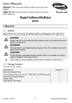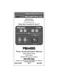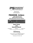
1
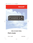
9800 Martel Road
Lenoir City, TN 37772
www.ps-engineering.com
PAR100EX
Audio Selector Panel
High-fidelity Stereo Intercom System
VHF Communications Transceiver Controller
Flying Never Sounded So Good! ®
Pilot’s Guide
and
Operation Manual
202-760-0100
Revision New
March 2010
Covered under one or more of the following Patents
No. 4,941,187, 5,903,227, 6,160,496, 6,493,450
Feb. 2011 PAR100EX Pilot Guide
202-760-0100
Page 1
This section provides detailed operating instructions for the PS Engineering
PAR100EX, Audio Selector Panel/Intercom/VHF Communication Control
Systems. Please read it carefully before using the equipment so that you can
take full advantage of its capabilities.
This section is divided into sections covering the basic operating areas of the
PAR100EX systems. They are Communications Transceiver Selection, Audio Selector, Intercom, VHF COM, entertainment, telephone, and display.
Power and Fail Safe (1)
Unit power is turned on and off by pushing the volume (left) knob. In the
OFF or "EMG" position, the pilot headset is connected directly to Com 1 as
well as unswitched input #1. This allows communication capability regardless of unit condition. Any time power is removed or turned OFF, the audio
selector portion will revert to fail-safe mode.
The power switch controls all audio selector panel functions and the intercom. All pushbutton selections and menu modes (except Bluetooth telephone
association) will be remembered and return to the last state when turned on.
Radio power (as COM 1)
The power supply for the remote communication transceiver is separate from
the audio panel power and control. When the M760 is installed as COM 1, or
as a stand-alone COM, it can be controlled separately in the event of a problem in the audio panel portion, or audio panel power.
If the audio panel is turned off by the left knob (or the audio panel breaker is
opened), the display will indicate “Push radio knob within 6 (countdown)
seconds to keep radio on” If the knob is not pushed, the com radio will also
turn off, but if the data knob is pushed within, the radiofrequency display,
volume and frequency control will remain active.
Communications Transmit (XMT) Selection (2)
The two buttons C1 and C2 (# 2) in the XMT section control which commuPage 2
202-760-0100
PAR100EX
Pilot Guide
nications radio is selected for transmit. The top row of pushbuttons (# 3)
allows selection of the receiver audio. Push the lower button to select the
desired COM transmitter. A green LED above the button illuminates to indicate that the audio is selected.
The PAR100EX-Series has an automatic com receiver selector system. Audio from the selected transceiver is automatically heard in the headsets and
speaker (if selected). You can check this function by switching from Com 1
transmitter to Com 2 transmitter by pressing the COM 2 transmitter selector
pushbutton. See that the associated Com 2 receive pushbutton indicator light
that is located immediately above the Com 2 transmitter pushbutton turns
green. This guarantees that the pilot will always hear the audio from the
transceiver selected for transmit.
The PAR100EX “remembers” the receiver selection, so that when switching
transmitters from COM 1 to COM 2, if COM 2 audio was previously selected,
COM 1 audio will continue to be heard. This eliminates the pilot having to
switch Com 1 audio back on, after changing transmitters.
When switching from COM 1 to COM 2 while Com 2 was not previously selected, COM 1 audio will be switched off. In essence, switching the mic selector will not override prior selection of COM
receiver audio.
In normal (not split) modes, the PAR100EX
gives priority to the pilot’s radio Push-To-Talk
(PTT). If the copilot it transmitting, and the
pilot presses his PTT, the pilot’s microphone
will be heard over the selected com transmitter.
Split Mode
The split mode can be activated at any time by
pressing the C1 and C2 XMT buttons at the same
time. This places the pilot on COM 1 and the Copilot
on COM 2.
Pilot on COM 2 and Copilot on COM 1 is not possible.
NOTE
Due to the nature of VHF communications signals, and the size constraints
in general aviation aircraft, it is probable that there will be some bleed-over
in the Split mode, particularly on adjacent frequencies. PS Engineering
makes no warranty about the suitability of Split Mode in all aircraft
conditions.
Swap Mode (Switch from Com 1 to Com 2 remotely)
With a yoke mounted, normally open momentary switch, the pilot can
change from the current Com transceiver to the other by depressing this
switch. To cancel "Swap Mode," the pilot may either press the yoke mounted
switch again, or select a different Com with the XMT buttons.
Feb. 2011 PAR100EX Pilot Guide
202-760-0100
Page 3
COM Audio Selector (3)
Communication audio from the other radio, not selected for transmit, can be
heard by pressing the associated RCV button. You will always hear the audio from the selected transceiver.
In SPLIT mode, only the pilot will hear selected navigation audio (A1 &
A2).
Navaid Audio selection (4)
VHF Navigation receiver audio is selected through two momentary, pushbutton, backlit switches.
The users can identify which receivers are selected by noting which green
LEDs are lit above the button. Navigation aid audio push buttons are labeled
A1, A2.
Any other installed receiver audio (Marker, ADF, etc) is interfaced through
an unswitched input.
VHF Transceiver control (5)
The right side of the PAR100EX is dedicated to control of the VHF communications transceiver. Frequency selection is always directed to the
STANDBY side of the display.
Frequency Selection (6)
Turn the large (outer) knob to change the frequency whole MHz, and the
smaller, inner knob to change the .100 MHz frequency.
Push the small knob momentarily to transfer standby frequency to the active
frequency.
Push momentarily
Radio Volume and Radio Squelch (7)
To change the radio volume, or defeat the automatic radio squelch, push and
hold the frequency-select knob for one second, until the display changes to
the volume and squelch menu.
Turn the large knob to decrease the radio squelch (to listen for weak signals),
and the small knob to adjust the radio receive audio level. You can push the
knob again to return to the frequency display, or the display will revert automatically after five seconds without any activity.
Page 4
202-760-0100
PAR100EX
Pilot Guide
Push/hold for
more than one
second
Monitor Mode
When interfaced with the M760R VHF COM radio as Com 1, the standby
frequency can be monitored by holding the C2 Receive button for the Microair for more than one second (or until the indicator becomes active).
Intercom Operation (8)
IntelliVox® VOX-Squelch
No manual adjustment of the IntelliVox® squelch control is possible.
Through individual signal processors, the ambient noise appearing in all four
microphones is constantly being sampled. Non-voice signals are blocked.
When someone speaks, only their microphone circuit opens, placing their
voice on the intercom.
The system is designed to block continuous tones; therefore people humming
or whistling in monotone may be blocked after a few moments.
For consistent performance, any headset microphone must be placed within
¼-inch of your lips, preferably against them. (ref: RTCA/DO-214, 1.3.1.1
(a)).
NOTE
It is also a good idea to keep the microphone out of a direct wind path. Moving your head through a vent air stream may cause the IntelliVox® to open
momentarily. This is normal.
The IntelliVox® is designed to work with normal aircraft cabin noise levels
(70 dB and above). It loves airplane noise! Therefore, it may not recognize
speech and clip syllables in a quiet cabin, such as in the hangar, or without
the engine running. This is normal.
For optimum microphone performance, PS Engineering recommends installation of a Microphone Muff Kit from Oregon Aero (1-800-888-6910). This
Feb. 2011 PAR100EX Pilot Guide
202-760-0100
Page 5
will not only optimize VOX performance, but will improve the overall clarity of all your communications.
Mic Muff ™ Part Numbers
Manufacturer
Model
Mic Muff™ Part Number
Bose
Dynamic
Electret
M87 Dynamic
90010
90015
90020
David Clark
H10-30
H10-20, H10-40
H10-13.4
90010
90015
90015
Lightspeed
All
90015
Peltor
7003
7004
90010
90015
Pilot
11-20 & 11-90
90015
90015
Sennheiser
Telex
Airman 750, Echelon
AIR3000
90015
90010
Volume Control (7)
The smaller, inner volume control knob adjusts the loudness of the intercom
for the pilot and copilot. It has no effect on selected radio levels, music input
levels or passengers' volume level.
The larger, outer volume control knob controls music input #1 volume, but
we recommend setting the volume on the device for the best level.
Adjust the radios and intercom volume for a comfortable listening level.
Most general aviation headsets today have built-in volume controls; therefore, volume also can be further adjusted at the individual headset.
Mono headsets in Stereo Installation
The pilot and copilot positions work with stereo or mono headsets. All passenger headsets are connected in parallel. Therefore, if a monaural headset is
plugged in to a PAR100EX Stereo installation, one channel will be shorted.
Although no damage to the unit will occur, passengers with stereo headsets
will only hear in one ear, unless they switch to the “MONO” mode on their
headset.
(Continued on page 9)
Page 6
202-760-0100
PAR100EX
Pilot Guide
Quick reference PAR100EX Operation
This pull-out section covers advanced operation of the
PAR100EX.
Frequency Selection
Turn the large (outer) knob to change the frequency whole MHz, and
the smaller, inner knob to change the .100 MHz frequency.
Push the small knob momentarily to transfer standby frequency to the
active frequency.
Push
momentarily
Radio Volume and Radio Squelch
To change the radio volume, or defeat the automatic radio squelch,
push and hold the frequency-select knob for one second, until the display changes to the volume and squelch menu.
Turn the large knob to turn the radio squelch on or off (to listen for
weak signals), and the small knob to adjust the radio receive audio
level. You can push the knob again to return to the frequency display,
or the display will revert automatically after five seconds without any
activity.
Push/hold for
more than one
second
Monitor Mode
When interfaced with the M760REM VHF COM radio as Com 1, the
standby frequency can be monitored by holding the C2 Receive button for the Microair for more than one second (or until the MON indicator becomes active).
Feb. 2011 PAR100EX Pilot Guide
202-760-0100
Page 7
Split Mode
The Split mode puts the pilot on COM 1, while the copilot can use
COM 2 independently. To enter the split mode, press both the C1 and
C2 XMT buttons at the same time.
To exit, press the desired COM 1 or COM 2 XMT button.
When you activate the Split mode, the intercom is put into ISO modde
to avoid confusion with multiple conversations. To reactivate the intercom, select a different intercom mode.
Note: Split Mode does not turn off selected radio audio to pilot. However, the copilot will only hear the selected com receiver and
unswitched inputs.
Telephone Operation
When the Bluetooth telephone is active, the telephone is added to the
intercom loop, and who is connected to the phone depends on the intercom mode. Calls can be placed and answered from the handset, but
the audio will be routed through the audio panel and aircraft audio
system.
ISO – The pilot is alone on the telephone
All – Everybody is on the telephone.
Crew – Pilot and copilot on telephone, passengers are not.
Music Muting
Music source #1 has four muting modes, which are announced in the headset as they are activated. These are:
Radio Mute (aircraft radio mutes music), Intercom Mute
(intercom conversation mutes music), Mute on (both radio
and intercom mutes music), and Mute off (nothing interrupts music). Press the Mute button to cycle through the
modes in sequence.
Music #2 has muting on or off, and is externally controlled.
Mode
LED
Intercom
Radio
Mute On
ON
Muted
Muted
Radio Mute
RAD
♫
Muted
Intercom Mute
ICS
Muted
♫
Mute Off
None
♫
♫
Page 8
202-760-0100
PAR100EX
Pilot Guide
(Continued from page 6)
Intercom Modes (8)
The “ICS” pushbutton switch on the lower left side of the panel provides the
selection of the three intercom modes. The description of the intercom mode
function is valid only when the unit is not in the "Split" mode.
This button cycles through the intercom modes, from left to right, then right
to left as: ISO, ALL CRW and CRW, ALL, ISO. An LED behind the text
shows which mode is currently active.
ISO: The pilot is isolated from the intercom and is connected only to the aircraft radio system. He will hear the aircraft radio reception (and sidetone
during radio transmissions). Copilot will hear passengers’ intercom and entertainment, while passengers will hear copilot intercom and entertainment.
Neither will hear aircraft radio receptions or pilot transmissions.
ALL: All parties will hear the aircraft radio and intercom. Crew and passengers will hear selected entertainment. During any radio or intercom communications, the music volume automatically decreases. The music volume
increases gradually back to the original level after communications have
been completed.
CREW: Pilot and copilot are connected on one intercom channel and have
exclusive access to the aircraft radios. They may also listen to Entertainment
1. Passengers can continue to communicate with themselves without interrupting the Crew and may listen to entertainment as configured.
Telephone Mode
Bluetooth Telephone Connection
Before the PAR100EX can be used in TELEPHONE mode with a wireless
Bluetooth connection, the unit
must be associated with a specific
phone.
Activate the “seek device” function on the cell phone, and then
enter the access code “0000” when
the phone detects the
“PAR100EX” on the list of available devices. When paired, “BT” is indicated on the display.
This process will be necessary for any phone to be used, and only one cell
phone can be associated with the audio panel at a time. If the additional
phones are associated with the PAR100EX at the same time, only the first
phone will transfer audio to the panel.
Telephone (TEL) Operation
When the Bluetooth-enabled phone receives an incoming call, the
PAR100EX will play a ring tone, and the BT in the display will blink. AnFeb. 2011 PAR100EX Pilot Guide
202-760-0100
Page 9
swer the call from your telephone handset. The PAR100EX exits the telephone mode automatically when the cellular phone hangs up.
In TELEPHONE mode, the pilot microphone and headphones are connected
to the cell phone. The pilot PTT will switch the pilot mic to the selected com
transceiver, and allow continued aircraft communications to continue.
The copilot will also be able to transmit on the other selected radio with his
PTT as well.
Entering the TEL mode connects the telephone to the users as follows:
In ALL intercom mode, all crew and passengers will be heard on the phone
when they speak. Com and other selected radio audio is also heard in the
headsets. If the pilot or copilot pushes the radio PTT, their mic will be transferred to the selected Com radio. The telephone party will not hear ATC
communications, and vice versa.
In CREW mode, only the pilot and copilot are connected to the telephone.
Passengers will not hear the telephone. The pilot and copilot will also have
transmit capability on the other selected transceiver.
In ISO intercom mode, when the PAR100EX is connected to the Bluetooth
telephone, the pilot position is in the "Phone Booth." Only the pilot will hear
the telephone, and only he will be heard. He will also have access to Com 1
or 2, and will transmit on that radio using the PTT. All selected audio is provided to the pilot.
NOTE
Because the cell-phone uses an intercom circuit, all stations on that circuit
will lose intercom capability when the cell phone is in use.
WARNING
Federal Communications Commission regulation 47 CFR 22.925 prohibits
the use of 800MHz Cellular handsets in any aircraft that is airborne. Violation of this rule could result in suspension of service and/or a fine.
Music Muting (9)
There are two SoftMute™ muting circuits. The front panel
"Mute" button has four modes, and controls the Mute function for music 1. Music 2 muting is controlled by an external
switch, and has two modes.
The SoftMute™ circuit will cut the music out whenever there
is conversation on the radio, the intercom, or both, depending
on the “Mute” mode selected. When that conversation stops,
the music returns to the previous level comfortably, over a
second or so.
The mute mode functions are controlled through sequential pushes of the
Mute button, and include LED indication of the mode selected.
Page 10
202-760-0100
PAR100EX
Pilot Guide
MUTE ON: Music will mute with either intercom or radio – MUTE
ON button is lit.
RADIO MUTE: Intercom will not mute music, radio will mute music.
RAD LED indicator is on
INTERCOM MUTE: Radio will not mute music, intercom will mute
music - MUTE ICS LED is ON.
MUTE OFF: “Karaoke” mode - music will not mute except during outgoing transmissions.- All Indicators off.
Intercom
Radio
LED
INDICATOR
Muted
Muted
ON
♫
Muted
RAD
ICS Mute
Muted
♫
ICS
Mute OFF
♫
♫
None
♫ Music
Mute ON
Radio Mute
The passengers’ intercom also has a SoftMute™ circuit. If the passengers hear the radio, or talk on the intercom, the music will mute. If
the audio panel is in CREW mode, then the radio reception will not
affect the passenger music.
Music 2 Mute Control
Passengers also have a Karaoke Mode. When the passengers are listening to the music 2 input, their Karaoke Mode is activated by an
external switch.
Liquid Crystal Display Control
The contrast on the LCD display can be controlled by using a service adjustment located on the top of the unit.
Feb. 2011 PAR100EX Pilot Guide
202-760-0100
Page 11
PAR100EX Serial Number: ____________________
M760R EM COM Serial Number: _______________
Installed by: ________________________________
Installation date: _____________________________
PS Engineering, Inc. 2011 © Copyright Notice
Copyrighted information in this manual is subject to change without notice. PS Engineering reserves the right to
improve or change the products or contents of this manual, without notification of any person or agency. The
contents of this pilot’s guide may be downloaded, stored and reprinted for personal use provided that this
copyright information is included. Commercial use is strictly prohibited. For further information contact the
Publications Manager at PS Engineering, Inc., 9800 Martel Road, Lenoir City, TN 37772. Phone (865) 9889800
Page 12
202-760-0100
PAR100EX
Pilot Guide