1
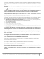
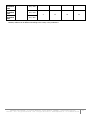
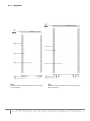
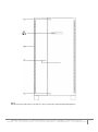
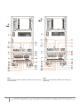
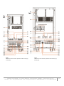
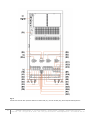
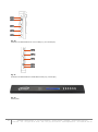
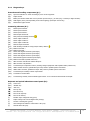
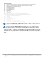
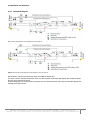
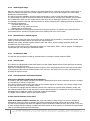
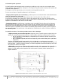
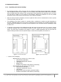
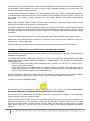
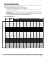
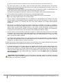
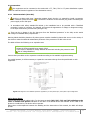
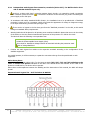
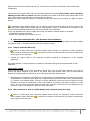
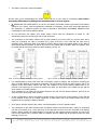
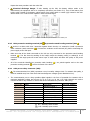
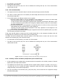
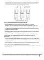
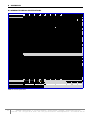
Remove shunts between terminals X4 and X17, X1 and X14, X2 and X15, X3 and X16 in case of Dual Input configuration. Connect the power supply cables N-R-S-T to the static bypass line terminals (X17), (X14), (X15) and (X16), adhering to the order of neutral and phases indicated on the label of the device and in this manual. If the order of the phases is not adhered to, the device will not operate. When there are discrepancies between the labelling and the instructions of this manual, the label will always prevail. In equipment with a separate bypass line, an isolation transformer must be placed at either or both of the UPS mains power supply inputs (rectifier input or static bypass), in order to avoid the direct connection of the neutral terminal with both mains through the internal wiring of the equipment. This is only applicable if the power supply comes from two different electrical mains, for example: - Two different electricity companies. - An electricity company and a generator set, etc. Separated static bypass line - M4T Evolution 100 and 120 kVA : The connection of separate static bypass on M4T UPS 100 and 120 kVA is done by adding the specific module (see page X and X), connection elements references remain the same. 4.3.3 Output, terminals (X6 to X9). • As this is a device with class I protection against electric shocks, it is essential to install a protective earth conductor (earth connection ( )). Connect the conductor to the terminal (X5), before connecting the power supply to the UPS input. • Connect the output cables to the respective terminals according to configuration of the available equipment. For parallel systems, it will be necessary to repeat the connections that go from the panel board to each equipment. Three phase output: Connect the load cables N-U-V-W to the output terminals (X9), (X6), (X7) and (X8), adhering to the order of neutral and phases indicated on the label of the device and in this manual. When there are discrepancies between the labelling and the instructions of this manual, the label will always prevail. • With respect to the compulsory protection on the UPS output, we recommend that the output power should be distributed in at least four lines. Each has a magnetic thermal protection switch with a value equivalent to a quarter of the nominal power. This type of power distribution means that only the faulty line will be affected in the event of a breakdown in any of the machines connected to the device resulting in a short circuit. The rest of the connected loads will have their continuity ensured due to the triggering of the protection, only the line affected by the short circuit will remain. 4.3.4 • UPS connection to each in-cabinet battery pack, terminals (X11, X12, X23). As this is a device with class I protection against electric shocks, it is essential to install a protective earth conductor (earth connection ( )). Connect the conductor to the terminal (X5), before connecting the power supply to the UPS input. INFOSEC UPS SYSTEM - 4, rue de la Rigotière - 44700 Orvault - FRANCE - www.infosec-ups.com Hot Line – Tel + 33 (0)2 40 76 15 82 - Fax + 33 (0)2 40 94 29 51 - [email protected] – 03 15 AA 59 201 38 39