1
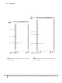
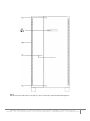
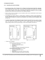
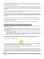
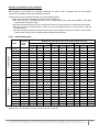
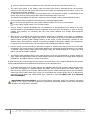
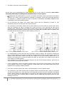
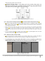
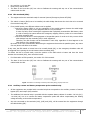
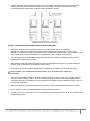
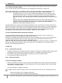
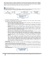
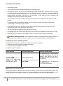
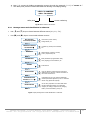
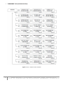
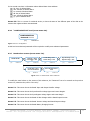
DO NOT TRY to perform this maneuver at any other moment, since this operation could damage the equipment and/or cause possible accidents. • Once the rectifier is fully functioning, a process of equalization (DC bus voltage starts to be equalized with battery voltage) will be started. After a few seconds (depending on the battery level), an alarm message will be displayed meaning that the equalizing process is over. The battery switch-fuse holder or switch of each UPS (Q3) can then be turned «On». DO NOT TRY to perform this maneuver at any other moment, since this operation could damage the equipment and/or cause possible accidents. If the equipment or parallel system has an outgoing distribution, turn its switches «On». Start up the loads to be supplied progressively. The joint is started up completely, and the loads are protected through the UPS or UPS parallel system. After the first start up, the usual start up/shutdown operation of an equipment or parallel joint will be done through the keypad of the control panel (PC). In parallel systems, it will be required to act over one of them only. Consider that the UPS or system will still be supplying output voltage, it does not matter the status of the own inverter or inverters: - Shutdown, from static bypass. - Started up, from inverter (On-line mode). - Started up, from static bypass (on Smart Eco-mode). 5.2.2.3 Considerations regarding Master and Slave (parallel systems only) • Bypass Master and Slave («Mst. Byp.», «Slv. Byp.», «Slv. By.Rsv»). o Master manages the status of the own solid-state static bypass switch and the one of the Slave equipments. o The equipments are not sharing the load in the inverters. The cause can be any of the following: Output switches (Q2) to position «Off». Equipment output on bypass. Inverters are shutdown or in start up process. o Voltage Master and Slave («Mst. Volt», «Slv. Volt», «Slv. Vt.Rsv»). Master manages the status of the own solid state static bypass switch and controls the inverter voltage, as well as the one of the Slave devices. o Devices are sharing the load in inverter. Therefore: Output switches (Q2) are «On». Inverter are operative and solid state switches are on inverter. 5.3 Shutdown of an equipment from the parallel system. Turn the output switch (Q2) of the UPS to shutdown, to position «Off». The screen 0.1 of the LCD panel will display: UPS: Normal, Invert. CFG: Paral. Not connected Screen 0.1 5.4 Start back the UPS of a parallel system. • • Start up the inverter with the keypad of the control panel (3) (see Fig. 27). From main screen press (▼) key to access to «CONTROL AND STATUS OF THE UNIT» submenu (screen 1.0), and then press (>) key. The screen 1.1 will be displayed, asking you to start the equipment up by pressing (ENT). Do so, and then validate the operation by pressing (ENT) again. See the diagram of Fig. 39. The UPS will take about 30 seconds to be operative again. Turn the output switch (Q2) of the UPS, to position «On». INFOSEC UPS SYSTEM - 4, rue de la Rigotière - 44700 Orvault - FRANCE - www.infosec-ups.com Hot Line – Tel + 33 (0)2 40 76 15 82 - Fax + 33 (0)2 40 94 29 51 - [email protected] – 03 15 AA 59 201 38 51