1
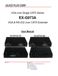
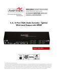
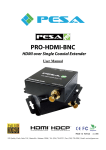
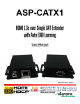
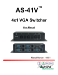
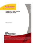
USERS GUIDE AS-CAT1-VGA VGA / YPbPr CAT Extender i Manual Number: 111101 User Guide SAFETY INSTRUCTIONS Please review the following safety precautions. If this is the first time using this model, then read this manual before installing or using the product. If the product is not functioning properly, please contact your local dealer or Aurora for further instructions. The lightning symbol in the triangle is used to alert you to the presence of dangerous voltage inside the product that may be sufficient to constitute a risk of electric shock to anyone opening the case. It is also used to indicate improper installation or handling of the product that could damage the electrical system in the product or in other equipment attached to the product. The exclamation point in the triangle is used to alert you to important operating and maintenance instructions. Failure to follow these instructions could result in injury to you or damage to the product. Be careful with electricity: Power outlet: To prevent electric shock, be sure the electrical plug used on the product power cord matches the electrical outlet used to supply power to the Aurora product. Use only the power adapter and power connection cables designed for this unit. Power cord: Be sure the power cord is routed so that it will not be stepped on or pinched by heavy items. Lightning: For protection from lightning or when the product is left unattended for a long period, disconnect it from the power source. . Also follow these precautions: Ventilation: Do not block the ventilation slots if applicable on the product or place any heavy object on top of it. Blocking the air flow could cause damage. Arrange components so that air can flow freely. Ensure that there is adequate ventilation if the product is placed in a stand or cabinet. Put the product in a properly ventilated area, away from direct sunlight or any source of heat. Overheating: Avoid stacking the Aurora product on top of a hot component such as a power amplifier. Risk of Fire: Do not place unit on top of any easily combustible material, such as carpet or fabric. Proper Connections: Be sure all cables and equipment are connected to the unit as described in this manual. Object Entry: To avoid electric shock, never stick anything in the slots on the case or remove the cover. Water Exposure: To reduce the risk of fire or electric shock, do not expose to rain or moisture. Cleaning: Do not use liquid or aerosol cleaners to clean this unit. Always unplug the power to the device before cleaning. ESD: Handle this unit with proper ESD care. Failure to do so can result in failure. FCC This device complies with Part 15 of the FCC Rules. Operation is subject to the following two conditions: (1) This device may not cause harmful interference. (2) This device must accept any interferences received, including interference that may cause undesired operation. Trademarks All trademarks in this document are the properties of their respective owners. i User Guide TABLE OF CONTENTS PACKAGE CONTENTS .............................................................................................................1 INTRODUCTION ........................................................................................................................2 About ..................................................................................................................................................... 2 Features ................................................................................................................................................ 2 Front & Rear Panel AS-CAT1-VGA-TX................................................................................................. 3 Front & Rear Panel AS-CAT1-VGA-RX ................................................................................................ 4 Bottom Panel AS-CAT1-VGA-RX ......................................................................................................... 5 QUICK START ...........................................................................................................................6 IR EXTENDERS .........................................................................................................................7 IR Connections ..................................................................................................................................... 7 IR Jack Pinout ....................................................................................................................................... 7 CONNECTOR PIN DEFINITION ................................................................................................8 APPENDIX 1 Troubleshooting .............................................................................................9 APPENDIX 2 Technical Specifications..............................................................................10 APPENDIX 3 Warranty ....................................................................................................... 11 ii User Guide PACKAGE CONTENTS Please make sure the following items are included within your package. Contact your dealer if any items are missing or damaged. AS-CAT1-VGA x 1 IR Receiver IR Blaster Power Adapter x 1 Note: Go to www.auroramultimedia.com for latest manual and firmware 1 User Guide INTRODUCTION About With only one cost effective Cat-5/5e/6 cable, the AS-CAT1-VGA lets you extend VGA (at WUXGA) or 720p component video, bi-directional IR control and half-duplex serial RS-232 at the same up to 330m (1,000ft). The AS-CAT1-VGA comes as a set of a transmitter and a receiver. The transmitting unit AS-CAT1-VGA-TX is installed near the signal source, and the receiving unit AS-CAT1-VGA-RX is placed near the desired VGA display. With the built-in equalization and signal gain control, the transmission path can be adjusted to adapt the cable quality and video bandwidth. Furthermore, the VGA RGB delay control [de-skew] function provides the compensation in arrival time among red, green and blue signal channels due to long transmission via normal Cat-5/5e/6 cable. With a commonly obtainable VGA-component breakout cable connected to the VGA port, the extender can support the component video for 330m (1,000ft) as well. Features Supports up to WUXGA [1920x1200@60] or UXGA [1600x1200@60] to 330m (1,000ft) Supports 720p component video signal to 330m (1,000ft) Supports RS-232 half-duplex & bi-directional IR pass-through Supports analog stereo audio and digital S/PDIF stereo audio Video and audio local out on transmitting unit for easy monitoring Adjustable equalization and gain control on receiving unit for signal tuning De-skew compensation for RGB delay control Wall mounting case & interlocked power jack 2 User Guide Front & Rear Panel AS-CAT1-VGA-TX 1 8 2 4 3 5 9 6 10 7 11 12 ①. IR-Blaster: connect to IR blaster for IR pass-through from RX to TX ②. RS-232: connect to a RS-232 signal source or receiver ③. Stereo IN: connect to analog audio source ④. S/PDIF IN: connect to digital audio source ⑤. Push-in button: select between S/PDIF and analog stereo audio [button down-S/PDIF, button up-Stereo] ⑥. VGA IN: connect to a VGA input source or a component video source via a VGA-component break cable ⑦. IR-Receiver: connect to IR receiver for IR pass-through from TX to RX ⑧. +5V DC: inter-locked power jack to connect to 5V DC power supply unit ⑨. Local VGA: VGA loop-out to a local VGA display or component video display via a VGA-component breakout cable ⑩. System OUT: plug in a Cat-5/5e/6 cable that needs to be linked to the RJ-45 connector of the receiving unit ⑪. Local S/PDIF: digital stereo audio loop-out ⑫. Local Stereo: analog stereo audio loop-out 3 User Guide Front & Rear Panel AS-CAT1-VGA-RX 1 7 2 8 6 5 4 3 9 10 11 12 13 ①. IR Receiver: connect to the IR receiver ②. RS-232: connect to a RS-232 device ③. Audio OUT: connect to analog audio output ④. S/PDIF OUT: connect to digital audio output ⑤. VGA OUT: VGA output to a VGA display or component video display via a VGA-component breakout cable ⑥. IR Blaster: connect to the IR blaster ⑦. +5V DC power jack: connect to 5V DC power supply unit ⑧. System IN: Plug in a Cat-5/5e/6 cable here to be linked to System OUT of the AS-CAT1-VGA-TX ⑨. EQUALIZER: Rotary control for signal equalization, i.e., equalizing the waveform of video signal, to the chosen RGB channel ⑩. GAIN: Rotary control for gain control, i.e., adjusting the amplitude of video signal, to the chosen RGB channel ⑪. RGB selector for selecting the respective R/G/B color channel for de-skew correction of VGA/YPbPr signal ⑫. RGB SKEW ADJUST “—“: Push-in button in step-by-step 2ns decreasing order for delay control on respective R/G/B color channel that is chosen by the RGB selector ⑬. RGB SKEW ADJUST ““: Push-in button in step-by-step 2ns increasing order for delay control on respective R/G/B color channel that is chosen by the RGB selector 4 User Guide Bottom Panel AS-CAT1-VGA-RX DIP Switch Position Description Pin#1 Pin#2 Pin#3 Pin#4 ON [] OFF [] ON [] OFF [] TX&RX Extender Mode – TxD1 of AS-CAT1-VGA-TX is connected to TxD of AS-CAT1-VGA-RX RxD2 of AS-CAT1-VGA-TX is connected to RxD of AS-CAT1-VGA-RX OFF [] ON [] OFF [] ON [] Master to Slave Mode – TxD of AS-CAT1-VGA-TX is connected to RxD AS-CAT1-VGA-RX RxD of AS-CAT1-VGA-TX is connected to TxD of AS-CAT1-VGA-RX 1. 2. TxD: The 3rd pin of RS-232, which is in charge of sending data RxD: The 2nd pin of RS-232, which is in charge of receiving data 5 User Guide QUICK START 1. Connect the VGA source, audio source, infrared and RS-232 devices to the transmitting unit AS-CAT1-VGA-TX. If you want to connect to a component video source, use a VGA to component breakout cable and link it between the video source and the transmitting unit of AS-CAT1-VGA. 2. Connect your VGA display, audio speaker, infrared and RS-232 devices to the receiving unit AS-CAT1-VGA-RX. If you want to connect to a component video display, use a VGA-component breakout cable and link it between the video display and the receiving unit of AS-CAT1-VGA. 3. Connect a Cat-5/5e/6 cable between the transmitting and receiving units. 4. Make sure this Cat-5/5e/6 cable is tightly connected and not loose. 5. Plug in 5V DC power supply unit to the power jack of the receiving unit AS-CAT1-VGA-RX. 6. Plug in 5V DC power supply unit to the power jack of the transmitting unit AS-CAT1-VGA -TX. 7. If you see the monitor is displaying blurred video or even worse, not displaying at all, please adjust the EQ and Gain rotary controls to improve the cable skew. GAIN rotary control is to adjust the gain to an appropriate level for a range of input signal levels (brightness), and EQ rotary control is to equalize the wave form of the receiving video signal (sharpness). It is suggested to begin with adjusting the rotary control of EQ to get the input video displayed first, and then the rotary control of GAIN according to the video you see on the screen. 8. RGB delay control (De-skew) offers the functionality to allow skew compensation for red, green, and blue color channels of the VGA signal for long distance or low quality cable. Dial the rotary arrow to choose RED, GREEN, or BLUE color channel first, then using the “push-in” buttons to increase or decrease the delay correction of the corresponding color channel. There are 31 steps in total. Each step represents 2-nanosecond time difference for adjusting the delay between each color individually. It is recommended to adjust RGB channels back and forth until the optimal visual quality is reached. 6 User Guide IR EXTENDERS IR Blaster IR Receiver IR Connections AS-CAT1-TX IR Blaster: Plug in an IR blaster here to emit all IR command signals received from the IR receiver on AS-CAT1-TX to control the associated devices with built-in IR sensor IR Receiver: Plug in an IR receiver here to receive all IR command signals from the IR remote controls of the associated devices AS-CAT1-RX IR Blaster: Plug in an IR blaster here to emit all IR command signals received from the IR receiver on AS-CAT1-RX to control the associated devices with built-in IR sensor IR Receiver: Plug in an IR receiver here to receive all IR command signals from the IR remote control of the IR source device. IR Jack Pinout IR Blaster IR Receiver You can buy any IR extension cables in the market that are compatible to the definition of the IR sockets for the matrix if necessary for replacement use. However, IR cables longer than 2m (6-ft) may not work. 7 User Guide CONNECTOR PIN DEFINITION Pair of Cat-5/5e/6 Cable Green Blue Orange Brown 8 Associated Definition Audio RED channel of VGA GREEN channel of VGA BLUE channel of VGA User Guide APPENDIX 1 Troubleshooting Problem 1. No Video Signal. 2. LED is not lit Solution a. Check that the power plug is properly inserted into a functioning power outlet. b. Make certain source is on. c. Try lower resolution to see if it is distance or cable grade issue. a. Check 5v power supply is plugged in. b. Check to see if Wall supply is plugged into wall outlet. c. Make certain wall outlet has power. 1. All transmission distances are measured using Belden 1583A CAT5e 125MHz Solid UTP cable and ASTRODESIGN Video Signal Generator VG-859C. The transmission distance is defined as the distance between the video source and the VGA display. 2. The transmission length is largely affected by the type of CAT5/6 cables, the type of VGA sources, and the type of VGA display. The testing result shows solid UTP cables (usually in the form of 300m or 1,000ft bulk cables) can transmit a lot longer signals than stranded UTP cables (usually in the form of fixed length patch cords). Shielded STP cables are better suited than unshielded UTP cables. A solid UTP CAT5e cable shows longer transmission range than stranded STP CAT6 cable. For long extension users, solid UTP/STP cables are the only viable choice. 3. To reduce the interference among the unshielded twisted pairs of wires in UTP cable, you can use shielded STP cables to improve EMI problems, which is worsen in long transmission. 4. Because the quality of the CAT5/6 cables has the major effect on how long the transmission limit can achieve and how good is the received picture quality, the actual transmission range is subject to one’s choice of CAT5/6 cables. For desired resolutions greater than 1080i or 1280x1024, a Cat-6 cable is recommended. Performance Guide for Video over CAT5/6 Cable Transmission Performance rating Wiring Shielding Unshielded (UTP) Solid Shielded (STP) Unshielded (UTP) Stranded Shielded (STP) Termination Type of CAT5/6 cable CAT5 CAT5e CAT6 Please use EIA/TIA-568-B termination (T568B) at any time 9 User Guide APPENDIX 2 Model Name Technical Role of usage Video bandwidth Video support Video Transmission Audio support RS-232 signal type Input video signal Equalization RGB delay control Loop-out ESD protection Input Output VGA connector RJ-45 connector Technical Specifications AS-CAT1-VGA AS-CAT1-VGA-TX Transmitter [TX] 350MHz VESA WUXGA [1920x1200] / 720p — 330m (1,000ft) [CAT5e] Stereo Half-duplex 1.2 Volts [peak-to-peak] Continuous analog control Yes 1 VGA local-out + 1 audio local-out at TX [1] Human body model — ±19kV [air-gap discharge] & ±12kV [contact discharge] [2] Core chipset — ±8kV 1x VGA + 1x RS-232 + 1x RJ-45 3x 3.5mm + 1x RCA 1x RJ-45 + 1x VGA + 1x VGA + 1x RS-232 + 1x 3.5mm + 1x RCA 1x RCA + 3x 3.5mm HD-15 [15-pin D-sub female] WE/SS 8P8C with 2 LED indicators RS-232 connector RCA connector 3.5mm connector Mechanical Housing Model Dimensions Package [L x W x H] Carton Model Weight Package Mounting Power supply Power consumption Operation temperature Storage temperature Relative humidity Package Contents AS-CAT1-VGA-RX Receiver [RX] DE-9 [9-pin D-sub female] S/PDIF digital audio Earphone jack for analog stereo audio or IR cable AS-CAT1-VGA Metal enclosure 123 x 91 x 36mm [4.8" x 3.5" x 1.5"] 330 x 200 x 95mm [1'1" x 7.9" x 3.7"] 495 x 440 x 380mm [1'7" x 1'5" x 1'3"] 395g [14 oz] 389g [13.7 oz] 1350g [3 lbs] Wall-mounting case with screws Inter-locked 5V 2A DC 6 Watts [max] 0~40C [32~104F] -20~60C [-4~140F] 20~90% RH [no condensation] 1x AS-CAT1-VGA 1x IR receiver 1x IR blaster 2x DC 5V 2A wall wart 1x User Manual Specifications subject to change without notice. 10 User Guide APPENDIX 3 Warranty Limited 3 Year Warranty Aurora Multimedia Corp. (“Manufacturer”) warrants that this product is free of defects in both materials and workmanship for a period of 3 years as defined herein for parts and labor from date of purchase. This Limited Warranty covers products purchased in the year of 2009 and after. Motorized mechanical parts (Hard Drives, DVD, etc), mechanical parts (buttons, doors, etc), remotes and cables are covered for a period of 1 year. Touch screen displays are covered for 1 year; touch screen overlay components are covered for 90 days. Supplied batteries are not covered by this warranty. During the warranty period, and upon proof of purchase, the product will be repaired or replaced (with same or similar model) at our option without charge for parts or labor for the specified product lifetime warranty period. This warranty shall not apply if any of the following: A. The product has been damaged by negligence, accident, lightning, water, act-of-God or mishandling; or, B. The product has not been operated in accordance with procedures specified in operating instructions: or, C. The product has been repaired and or altered by other than manufacturer or authorized service center; or, D. The product's original serial number has been modified or removed: or, E. External equipment other than supplied by manufacturer, in determination of manufacturer, shall have affected the performance, safety or reliability of the product. F. Part(s) are no longer available for product. In the event that the product needs repair or replacement during the specified warranty period, product should be shipped back to Manufacturer at Purchaser's expense. Repaired or replaced product shall be returned to Purchaser by standard shipping methods at Manufacturer's discretion. Express shipping will be at the expense of the Purchaser. If Purchaser resides outside the contiguous US, return shipping shall be at Purchaser's expense. No other warranty, express or implied other than Manufacturer's shall apply. Manufacturer does not assume any responsibility for consequential damages, expenses or loss of revenue or property, inconvenience or interruption in operation experienced by the customer due to a malfunction of the purchased equipment. No warranty service performed on any product shall extend the applicable warranty period. This warranty does not cover damage to the equipment during shipping and Manufacturer assumes no responsibility for such damage. 11 www.auroramultimedia.com User Guide This product warranty extends to the original purchaser only and will be null and void upon any assignment or Aurora Multimedia Corp. 205 Commercial Court Morganville, NJ 07751 Phone: 732-591-5800 12 Fax: 732-591-6801