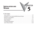
1
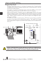
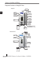
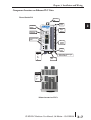
Installation and Wiring Chapter 3 In This Chapter... Safety Guidelines............................................................................... 3–2 Introduction to the CLICK PLC Mechanical Design........................... 3–5 Mounting Guidelines...................................................................... 3–11 Installing the CLICK PLC................................................................. 3–16 Wiring Guidelines............................................................................ 3–18 I/O Wiring Checklist........................................................................ 3–24 System Wiring Strategies................................................................. 3–25 Analog I/O Configuration................................................................ 3–36 Chapter 3: Installation and Wiring A 2 3 3 3 3 3 3 3 3 3 3 3 3 3 3 3 3 Safety Guidelines NOTE: Products with CE marks perform their required functions safely and adhere to relevant standards as specified by CE directives, provided they are used according to their intended purpose and that the instructions in this manual are followed. The protection provided by the equipment may be impaired if this equipment is used in a manner not specified in this manual. A listing of our international affiliates is available on our Web site at http://www.automationdirect.com. Warning: Providing a safe operating environment for personnel and equipment is your responsibility and should be your primary goal during system planning and installation. Automation systems can fail and may result in situations that can cause serious injury to personnel or damage to equipment. Do not rely on the automation system alone to provide a safe operating environment. You should use external electromechanical devices, such as relays or limit switches, that are independent of the PLC application to provide protection for any part of the system that may cause personal injury or damage. Every automation application is different, so there may be special requirements for your particular application. Make sure you follow all national, state, and local government requirements for the proper installation and use of your equipment. Plan for Safety The best way to provide a safe operating environment is to make personnel and equipment safety part of the planning process. You should examine every aspect of the system to determine which areas are critical to operator or machine safety. If you are not familiar with PLC system installation practices, or your company does not have established installation guidelines, you should obtain additional information from the following sources. • NEMA — The National Electrical Manufacturers Association, located in Washington, D.C., publishes many different documents that discuss standards for industrial control systems. You can order these publications directly from NEMA. Some of these include: ICS 1, General Standards for Industrial Control and Systems ICS 3, Industrial Systems ICS 6, Enclosures for Industrial Control Systems • NEC — The National Electrical Code provides regulations concerning the installation and use of various types of electrical equipment. Copies of the NEC Handbook can often be obtained from your local electrical equipment distributor or your local library. • Local and State Agencies — many local governments and state governments have additional requirements above and beyond those described in the NEC Handbook. Check with your local Electrical Inspector or Fire Marshall office for information. 3–2 CLICK PLC Hardware User Manual, 5th Edition – C0-USER-M Chapter 3: Installation and Wiring Three Levels of Protection Warning: The control program must not be the only form of protection for any problems that may result in a risk of personal injury or equipment damage. The publications mentioned provide many ideas and requirements for system safety. At a minimum, you should follow these regulations. Also, you should use the following techniques, which provide three levels of system control. 1. Orderly system shutdown sequence in the PLC control program Jam Detect 2. Mechanical disconnect for output module power 3. Emergency stop switch for disconnecting system power Turn off Saw RST RST Retract Arm Orderly System Shutdown The first level of fault detection is ideally the PLC control program, which can identify machine problems. These types of problems are usually things such as jammed parts, etc., that do not pose a risk of personal injury or equipment damage. However, respective shutdown sequences should be performed. System Power Disconnect You should also use electromechanical devices, such as master control relays and/or limit switches, to prevent accidental equipment startup at an unexpected time. These devices should be installed in a manner that will prevent any machine operations from occurring. For example, if the machine in the illustration has a jammed part, the PLC control program can turn off the saw blade and retract the arbor. If the operator must open the guard to remove the part, you should also include a bypass switch that disconnects all system power any time the guard is opened. CLICK PLC Hardware User Manual, 5th Edition – C0-USER-M 3–3 A 2 3 3 3 3 3 3 3 3 3 3 3 3 3 3 3 3 Chapter 3: Installation and Wiring Emergency Stop Circuits A 2 3 3 3 3 3 3 3 3 3 3 3 3 3 3 3 3 Emergency stop (E-Stop) circuits are a critical part of automation safety. For each machine controlled by a PLC, provide an emergency stop device that is wired outside the PLC and easily accessed by the machine operator. E-stop devices are commonly wired through a master control relay (MCR) or a safety control relay (SCR) that will remove power from the PLC I/O system in an emergency. MCRs and SCRs provide a convenient means for removing power from the I/O system during an emergency situation. By de-energizing an MCR (or SCR) coil, power to the input (optional) and output devices is removed. This event occurs when any emergency stop switch opens. However, the PLC continues to receive power and operate even though all its inputs and outputs are disabled. The MCR circuit could be extended by placing a PLC fault relay (closed during normal PLC operation) in series with any other emergency stop conditions. This would cause the MCR circuit to drop the PLC I/O power in case of a PLC failure (memory error, I/O communications error, etc.). L Use E-Stop and Master Control Relay E-Stop Guard Limit Switch Emergency Stop Master Control Relay MCR Limit Switch Power On MCR E-Stop C - RC P R RU ERR RU C S OP POR R C R POR C MCR MCR CR CR Saw Arbor Warning: For some applications, field device power may still be present on the terminal block even though the PLC is turned off. To minimize the risk of electrical shock, remove all field device power before you expose or remove PLC wiring. The connector is designed for easy removal by hand. 3–4 CLICK PLC Hardware User Manual, 5th Edition – C0-USER-M Chapter 3: Installation and Wiring Introduction to the CLICK PLC Mechanical Design CLICK PLC Units All CLICK PLCs are similar in appearance. Please see the diagrams below to familiarize yourself with the PLC features. The main components located on the front of the PLC are a removable 20-pin I/O connector, Run/Stop switch, communications ports and LED status indicators. A removable 4-pin 24VDC input power connector is located on the bottom of the PLC. The I/O module extension port is located on the right side of the PLC case. See Mounting Guidelines in this chapter for module dimensions and Chapter 2 for CLICK PLC specifications. Component Locations on Basic and Standard PLC Units Mounting Tab Basic PLC Sliding Latch PLC Mode Switch 8 Discrete Input Points LED Status Indicators Communication Ports 6 Discrete Output Points Sliding Latch Power Terminal 24V 0V N.C. G Removeable Screw Type Terminal Block Mounting Tab Mounting Tab Standard PLC PLC Mode Switch C0-01DD1-D LED Status Indicators Sliding Latch 8 Discrete Input Points PWR RUN ERR PORT1 Communication Ports TX1 RX1 TX2 6 Discrete Output Points RX2 PORT2 PORT3 RS-485 TX3 RX3 Power Terminal 24V 0V N.C. G Sliding Latch Removeable Screw Type Terminal Block Mounting Tab CLICK PLC Hardware User Manual, 5th Edition – C0-USER-M 3–5 A 2 3 3 3 3 3 3 3 3 3 3 3 3 3 3 3 3 Chapter 3: Installation and Wiring Component Locations on Analog PLC Units A 2 3 3 3 3 3 3 3 3 3 3 3 3 3 3 3 3 Analog PLC Mounting Tab PLC Mode Switch C0-02DD1-D Sliding Latch C1 X1 X2 X3 LED Status Indicators PWR X4 RUN C2 ERR Y1 Y2 PORT1 Y3 TX1 Y4 RX1 +V AD1V Communication Ports TX2 AD1 I RX2 AD2V PORT2 PORT3 4 Discrete Inputs 4 Discrete Outputs 2 Analog Inputs AD2 I ACOM RS-485 DA1V TX3 DA1 I RX3 DA2V 2 Analog Outputs DA2 I Sliding Latch Power Terminal 24V 0V N.C. G Removeable Screw Type Terminal Block Mounting Tab Ethernet Basic PLC Mounting Tab C0-10DD1E-D C0-10DD1E-D D PLC Mode Switch C1 X1 X2 2 LED Status Indicators PWR RUN RUN RUN ERR Communication Ports X3 3 X4 4 STOP STOP X5 5 LNK/ACT ETHER NET 100MBIT X6 6 TX2 RX2 RS-232 RS 232 8 Discrete Input Points C2 2 PORT1 PORT2 S Sliding Latch L X7 7 X8 8 C3 3 Y1 Y2 2 Y3 3 Y4 4 C4 4 6 Discrete Output Points Y5 5 Y6 6 +V V Power wer Terminal rminal 24V 0V N.C. G 3–6 S Sliding Latch L Mounting Tab CLICK PLC Hardware User Manual, 5th Edition – C0-USER-M Chapter 3: Installation and Wiring Component Locations on Ethernet PLC Units Ethernet Standard PLC A 2 3 3 3 3 3 3 3 3 3 3 3 3 3 3 3 3 Mounting Tab PLC Mode Switch C0-11DD1-D 8 Discrete Input Points PWR LED Status Indicators Sliding Latch RUN ERR PORT1 LINK/ACT ETHER NET Communication Ports 100MBIT PORT2 TX2 6 Discrete Output Points RX2 RS-232 PORT3 RS-485 TX3 RX3 Power Terminal 24V 0V N.C. G Sliding Latch Removeable Screw Type Terminal Block Mounting Tab Power al Terminal 24V 0V N.C. G Bottom view same for all PLC’s CLICK PLC Hardware User Manual, 5th Edition – C0-USER-M 3–7 Chapter 3: Installation and Wiring CLICK I/O Modules A 2 3 3 3 3 3 3 3 3 3 3 3 3 3 3 3 3 Several different types of input and output modules are available for the CLICK PLC system. Please see the diagrams below to familiarize yourself with the I/O module features. Each I/O module is identified as an Input or Output module on its front panel using the color coding scheme listed below. Up to eight I/O option modules can be connected to a CLICK PLC. See Mounting Guidelines in this chapter for module dimensions and Chapter 2 for CLICK I/O module specifications. Output Modules Input Modules Mounting Tab Sliding Latch Mounting Tab Module Part Number Power Indicator (Green: Module Power Good) Module Type (Blue: Input) Power Indicator (Green: Module Power Good) Input Point Status Indicators (Green: ON) Mounting Tab 3–8 Removable Terminal Block Sliding Latch Module Part Number Module Type (Red: Output) DIN Rail Slot and I/O Module Port Extension Module Input Point Identifier Sliding Latch DIN Rail Slot and I/O Module Port Extension Output Point Status Indicators (Red: ON) Mounting Tab CLICK PLC Hardware User Manual, 5th Edition – C0-USER-M Module Output Point Identifier Removable Terminal Block Sliding Latch Chapter 3: Installation and Wiring CLICK Power Supplies All CLICK PLCs require 24VDC input power from either a CLICK power supply or other suitable external power supply. Two models of CLICK power supplies are available to supply power to the PLC and I/O modules. • C0-00AC - 0.5A @ 24VDC output • C0-01AC - 1.3A @ 24VDC output Select a power supply based on the power requirements of your system components. See Mounting Guidelines in this chapter for module dimensions and Chapter 2 for CLICK power supply specifications. Power wires must be connected from the output terminals on the front of the power supply to the input power connector on the bottom of the CLICK PLC (There is no internal 24VDC power bus to the PLC.) See Mounting Guidelines for additional wiring information. Only a single CLICK power supply can be attached directly to a CLICK PLC system. If multiple CLICK power supplies are used, or if other type of power supplies are used, mount them separately from the PLC. For example, the PSP24-DC12-1 DC-DC converter shown below must be mounted separately from the PLC. C0-00AC and C0-01AC Power Supplies Component Locations Mounting Tab Sliding Latch Power Supply Part Number 24VDC Output Power Terminals (for CLICK PLC, I/O or field device, etc.) 85-264 VAC Power Source Input Terminals Sliding Latch Mounting Tab The PSP24-DC12-1 DC-DC converter must be mounted separately from the PLC. CLICK PLC Hardware User Manual, 5th Edition – C0-USER-M 3–9 A 2 3 3 3 3 3 3 3 3 3 3 3 3 3 3 3 3 Chapter 3: Installation and Wiring Battery Backup (Standard, Analog and Ethernet PLC Units) In Standard, Analog and Ethernet PLC units, an optional lithium battery is available to maintain the data in SRAM when the system is without external power. Use battery part number D2-BAT-1 (not included with the PLC module; order battery separately). Typical battery life is 5 years, which includes PLC runtime and normal shutdown periods. A 2 3 3 3 3 3 3 3 3 3 3 3 3 3 3 3 3 Note: We recommend that you install and/or change the battery while the PLC is powered up. To install or replace the D2-BAT-1 battery: 1. Press the retaining clip on the battery door and swing the battery door open. 2. Install the battery into the coin-type slot with the +, or flat, side out. 3. Close the battery door so that it locks securely. 4. Make a note of the date the battery was installed. The battery backup is now available. WARNING: Do not attempt to recharge the battery or dispose of it by fire. The battery may explode or release hazardous materials. The CLICK PLC has a feature to indicate that the pre-scheduled battery replacement date has been passed. On the CLICK programming software, go to the pull-down menu: Setup > Battery backup Setup. 3–10 CLICK PLC Hardware User Manual, 5th Edition – C0-USER-M Chapter 3: Installation and Wiring Mounting Guidelines Environmental Specifications The CLICK family of PLC products should be stored, installed, and used within their range of environmental specifications, such as storage temperature, operating temperature, humidity, environmental air, vibration, shock, and noise immunity. Certain output module circuit types may have derating curves depending on the ambient temperature and the number of outputs ON. Refer to the I/O module specifications in Chapter 2: Specifications for CLICK PLC environmental specifications and I/O module derating curves. Agency Approvals In addition to the panel layout guidelines, other specifications can affect the definition and installation of a PLC system. Always consider the following: • Environmental Specifications • Power Requirements • Agency Approvals • Enclosure Selection and Component Dimensions CLICK Unit Dimensions The following diagrams illustrate the dimensions of the CLICK power supply, CLICK PLC, and I/O modules. The CLICK PLC system is designed to be mounted on standard 35mm DIN rail, or it can be surface mounted. See the following pages for installations and mounting information, including page 3-17 for DIN rail and surface-mounting instructions. Unit Dimensions mm [inches] Power Supply NOTE: The dimensions for the C0-00AC and C0-01AC power supplies are the same. CLICK PLC Hardware User Manual, 5th Edition – C0-USER-M 3–11 A 2 3 3 3 3 3 3 3 3 3 3 3 3 3 3 3 3 Chapter 3: Installation and Wiring Unit Dimensions mm [inches] A 2 3 3 3 3 3 3 3 3 3 3 3 3 3 3 3 3 PLC Unit I/O Module 3–12 CLICK PLC Hardware User Manual, 5th Edition – C0-USER-M Chapter 3: Installation and Wiring Unit Dimensions mm [inches] PLC Unit System 2.6 [0.102] 34.9 [1.37] 53.5 [2.11] 27 [1.06] 13.5 [0.46] 75 [2.95] 85 5 .35] 5 [3.35] 4 [0.16] " 9.4 [0.37] 9.2 [0.36] Maximum system: Power Supply + PLC + eight I/O modules. Follow the installation guidelines to allow for proper spacing from other components within an enclosure. 304.4 [11.98] C0-01AC CLICK PLC Hardware User Manual, 5th Edition – C0-USER-M 3–13 A 2 3 3 3 3 3 3 3 3 3 3 3 3 3 3 3 3 Chapter 3: Installation and Wiring Enclosures • Conformance to electrical standards • Protection from the elements in an industrial environment • Common ground reference • Maintenance of specified ambient temperature • Access to equipment • Security or restricted access • Sufficient space for proper installation and maintenance of equipment Panel Layout and Clearances PORT1 TX1 RX1 TX2 RX2 PORT2 RUN STOP 1. Mount the CLICK PLC unit (system) horizontally as shown below to provide proper ventilation. Do not mount the CLICK PLC units upside down, on a horizontal surface or in a vertical arrangement. If you place more than one unit in a cabinet, there must be a minimum of 7.2” (183mm) between the units. PWR RUN ERR A 2 3 3 3 3 3 3 3 3 3 3 3 3 3 3 3 3 Your selection of a proper enclosure is important to ensure safe and proper operation of your CLICK PLC system. Control applications vary and yours may require additional considerations. At a minimum your enclosure should include: Air Flow 2. P rovide a minimum clearance of 2” (50mm) between the unit and all sides of the cabinet. Note: Remember to allow clearance for any operator panels or other items mounted directly in front of the unit in the door. 3. There should also be at least 3” (78mm) of clearance between the unit and any wiring ducts that run parallel to the terminals. 4. The ground terminal on the CLICK PLC must be connected to a single point ground. Use copper stranded wire to achieve a low impedance. Copper eye lugs should be crimped and soldered to the ends of the stranded wire to ensure good surface contact. 5. There must be a single point ground (i.e. copper bus bar) for all devices in the panel requiring an earth ground return. The single point of ground must be connected to the panel ground termination. The panel ground termination must be connected to ground. Minimum wire sizes, color coding, and general safety practices should comply with appropriate electrical codes and standards for your area. 3–14 CLICK PLC Hardware User Manual, 5th Edition – C0-USER-M Chapter 3: Installation and Wiring NOTE: There is a minimum clearance requirement of 2” (51 mm) between the CLICK PLC and the panel door or any devices mounted in the panel door. The same clearance is required between the PLC and surrounding enclosure. NOTE: A minimum clearance of 3” (76 mm) is required between the PLC and a wireway or any heat producing device. 2 in. 50.8 mm minimum Ground Braid Copper Lugs 2 in. 50.8mm minimum 3 in. 76.2 mm minimum Panel or Single Point Ground Panel Star Washers Star Washers 6. A good common ground reference (Earth ground) is essential for proper operation of the CLICK PLC. One side of all control and power circuits and the ground lead on flexible shielded cable must be properly connected to Earth ground. There are several methods of providing an adequate common ground reference, including: a) Installing a ground rod as close to the panel as possible b) Connection to incoming power system ground 7. Evaluate any installations where the ambient temperature may approach the lower or upper limits of the specifications. If you suspect the ambient temperature will not be within the operating specification for the CLICK PLC system, measures such as installing a cooling/heating source must be taken to get the ambient temperature within the range of specifications. 8. CLICK PLC systems are modular and can be powered by any suitable 24 VDC power supply. The optional CLICK power supply is designed to attach to the left side of the CLICK PLC case. CLICK power supplies accept 85-264 VAC and produce nominal 24 VDC to power the CLICK PLC and I/O modules. Powerline filters are recommended for protecting the CLICK PLC from power surges and EMI/RFI noise. The AutomationDirect Powerline Filter, for use with 120 VAC and 240 VAC, 1–5 Amps, is an excellent choice (locate at www.automationdirect.com), however, you can use a filter of your choice. The filter units install easily between the AC power source and the PLC. CLICK PLC Hardware User Manual, 5th Edition – C0-USER-M 3–15 A 2 3 3 3 3 3 3 3 3 3 3 3 3 3 3 3 3 Chapter 3: Installation and Wiring A 2 3 3 3 3 3 3 3 3 3 3 3 3 3 3 3 3 Installing the CLICK PLC Connecting the Modules Together CLICK PLCs and I/O modules connect together using the Extension Ports that are located on the side panels of the modules. The modules secure together by sliding LOCK/UNLOCK latch tabs located on the top and bottom panels of the modules. A PLC backplane or base is not required. When connecting an I/O module to the PLC, first remove the Extension Port covers, slide the latches forward (unlock), align the module pins, and press the I/O module onto the PLC’s right side. Slide the latches backward to lock the modules together. NOTE: If you are using other components in your system, make sure you refer to the appropriate manual to determine how those units can affect mounting dimensions. Latch Tabs 3 2 1) Remove extension port covers and slide latch tabs forward. 2) Align the module pins and connection plug, and press the I/O module onto the right side of the PLC. 3) Slide the latch tabs backward to lock the modules together. 1 3–16 CLICK PLC Hardware User Manual, 5th Edition – C0-USER-M Chapter 3: Installation and Wiring Mounting CLICK PLC System on DIN Rail CLICK PLCs can be secured to a panel by using mounting rails. We recommend rails that conform to DIN EN standard 50 022. They are approximately 35mm high, with a depth of 7mm. If you mount the CLICK PLC on a rail, consider using end brackets on each side of the PLC. The end bracket helps keep the PLC from sliding horizontally along the rail, reducing the possibility of accidentally pulling the wiring loose. On the bottom of the PLC is a small retaining clip. To secure the PLC to a DIN rail, place it onto the rail and gently push up on the clip to lock it onto the rail. To remove the PLC, pull down on the retaining clip, lift up on the PLC slightly, then pull it away from the rail. DN-EB35MN Pull tab down. Push tab up until... Click NOTE: When mounting on DIN rail, using DINnectors end brackets at both ends is recommended (part number DN-EB35MN). Optional Mounting Method The CLICK PLC system can be secured to the equipment panel or desired location using the mounting tabs located on the back panel of the PLC, I/O modules and power supplies. Extend the upper and lower retaining clips to the full out position. Mount using M4 screws in the center hole of the tabs. Upper Mouting Tab Lower Mouting Tab CLICK PLC Hardware User Manual, 5th Edition – C0-USER-M 3–17 A 2 3 3 3 3 3 3 3 3 3 3 3 3 3 3 3 3 Chapter 3: Installation and Wiring A 2 3 3 3 3 3 3 3 3 3 3 3 3 3 3 3 3 Wiring Guidelines Power Input Wiring to CLICK Power Supply Connect the AC power source input wiring to the CLICK power supply (the CLICK power supply voltage and current requirements are listed in chapter 2). If you are not using a CLICK power supply, be sure that it meets CLICK PLC requirements. Do not apply power at this time. Observe all precautions stated earlier in this manual. Warning: Once the power wiring is connected, secure the terminal block cover in the closed position. When the cover is open there is a risk of electrical shock if you accidentally touch the connection terminals or power wiring. Power Input Wiring to CLICK PLC Connect the 24 VDC power source input wiring to the 4-pin 24 VDC input connector located on the bottom panel of the CLICK PLC. Do not apply power at this time. Observe all precautions stated earlier in this manual. CLICK PLC CLICK Power Supply 24VDC 0V G 3–18 CLICK PLC Hardware User Manual, 5th Edition – C0-USER-M 24VDC 0V G Chapter 3: Installation and Wiring Fuse Protection Fuse Protection for PLC Input Power External circuit protection is needed to ensure the safety of service personnel and the safe operation of the equipment itself. To meet UL/CUL specifications, the input power must be fused. Fuse the AC side of the power supply that provides the 24 VDC power to the CLICK PLC. When operating the power supply from a 110/120V AC system with a grounded neutral, it is only necessary to fuse the line (L) lead; it is not necessary to fuse the grounded neutral (N) lead. Select the fuse size based on the input current draw of the power supply. Refer to Chapter 2 of this manual for specifications of CLICK power supplies. Fuse Protection for I/O Module Circuits Input and Output circuits on CLICK PLCs do not have internal fuses. In order to protect your PLC, we suggest you add external fuses to your I/O wiring. A fast-blow fuse, with a lower current rating than the I/O bank’s common current rating can be wired to each common. Or, a fuse with a rating of slightly less than the maximum current per output point can be added to each output. Refer to the I/O module specifications in Chapter 2 to find the maximum current per output point or per output common. Adding the external fuse does not guarantee the prevention of PLC damage, but it will provide added protection. The discrete inputs and outputs will be damaged if the signal exceeds the rated voltage. CLICK PLC Hardware User Manual, 5th Edition – C0-USER-M 3–19 A 2 3 3 3 3 3 3 3 3 3 3 3 3 3 3 3 3 Chapter 3: Installation and Wiring Planning the I/O Wiring Routes The following guidelines provide general information on how to wire the I/O connections to CLICK PLCs. For additional information about wiring a particular I/O type refer to the corresponding information in this chapter. 1. Each terminal connection of the CLICK PLC can accept one 16 AWG wire or two 18 AWG size wires. Do not exceed this recommended capacity. Refer to Chapter 2 Specifications for more detailed specifications of the terminal blocks. 2. Always use a continuous length of wire. Do not splice wires to attain a needed length. 3. Use the shortest possible wire length. 4. Use wire trays for routing where possible. 5. Avoid running lower voltage wires near higher voltage wiring. 6. Avoid running input wiring close to output wiring where possible. 7. To minimize voltage drops when wires must run a long distance, consider using multiple wires for the return line. 8. Avoid running DC wiring in close proximity to AC wiring where possible. 9. Avoid creating sharp bends in the wires. 10. Install the recommended powerline filter to reduce power surges and EMI/RFI noise. A 2 3 3 3 3 3 3 3 3 3 3 3 3 3 3 3 3 3–20 CLICK PLC Hardware User Manual, 5th Edition – C0-USER-M Chapter 3: Installation and Wiring Wiring I/O Modules There are two sizes of I/O module terminal blocks used for field wiring connections (11pt. & 20pt.), and they can be removed from the module for wiring convenience. There are no clips or screws retaining the terminal block. Firmly grip the block and pull it away from the PLC or I/O module. The connector terminal points have recessed screws to help minimize the risk of someone accidentally touching active wiring. Make sure the terminal blocks are properly seated against the module when replacing them. For your convenience we also have DINnectors, DIN-rail mounted terminal blocks. Refer to our website or catalog for a complete listing of all available products. We strongly recommend using our ZIPLinks connections systems. See the following pages for ZIPLinks compatability and special pre-assembled cables, with the I/O connectors installed and wired. ZIPLinks Connection Systems ZIPLinks Cables with Connectors ZIPLinks Modules Warning: For some modules, field device power may still be present on the terminal block even though the PLC system is turned off. To minimize the risk of electrical shock and equipment damage, check all field device power before you remove the connector. CLICK PLC Hardware User Manual, 5th Edition – C0-USER-M 3–21 A 2 3 3 3 3 3 3 3 3 3 3 3 3 3 3 3 3 Chapter 3: Installation and Wiring ZIPLink Wiring System Compatibility Matrix for CLICK PLCs Use the following tables to select your ZIPLink components. See our website for more specifications and information on ZIPLinks. A 2 3 3 3 3 3 3 3 3 3 3 3 3 3 3 3 3 PLC CLICK PLC Units ZIPLink Selector ZIPLink PLC Module # of Terms Component C0-00DD1-D C0-00DD2-D C0-00DR-D C0-00AR-D C0-01DD1-D C0-01DD2-D C0-01DR-D C0-01AR-D C0-02DD1-D C0-02DD2-D C0-02DR-D C0-10DD1E-D C0-10DD2E-D C0-10DRE-D C0-10ARE-D C0-11DD1E-D C0-11DD2E-D C0-11DRE-D C0-11ARE-D 20 20 20 20 20 20 20 20 20 20 20 20 20 20 20 20 20 20 20 Feedthrough Feedthrough Feedthrough Feedthrough Feedthrough Feedthrough Feedthrough Feedthrough Module Part Cable Part No. No. ZL-RTB20 ZL-RTB20 ZL-RTB20 ZL-RTB20 ZL-RTB20 ZL-RTB20 ZL-RTB20 ZL-RTB20 ZL-C0-CBL20* ZL-C0-CBL20* ZL-C0-CBL20* ZL-C0-CBL20* ZL-C0-CBL20* ZL-C0-CBL20* ZL-C0-CBL20* ZL-C0-CBL20* No ZIPLinks are available for analog PLC units. Feedthrough Feedthrough Feedthrough Feedthrough Feedthrough Feedthrough Feedthrough Feedthrough ZL-RTB20 ZL-RTB20 ZL-RTB20 ZL-RTB20 ZL-RTB20 ZL-RTB20 ZL-RTB20 ZL-RTB20 ZL-C0-CBL20* ZL-C0-CBL20* ZL-C0-CBL20* ZL-C0-CBL20* ZL-C0-CBL20* ZL-C0-CBL20* ZL-C0-CBL20* ZL-C0-CBL20* * Select the cable length by replacing the * with: Blank = 0.5m, -1 = 1.0m, or -2 = 2.0m. CLICK PLC Discrete Input Module ZIPLink Selector I/O Module ZIPLink Input Module # of Terms Component C0-08ND3 C0-08ND3-1 C0-08NE3 C0-08NA 11 11 11 11 C0-16ND3 20 C0-16NE3 20 Feedthrough Feedthrough Feedthrough Feedthrough Feedthrough Sensor Feedthrough Sensor Module Part No. Cable Part No. ZL-RTB20 ZL-RTB20 ZL-RTB20 ZL-RTB20 ZL-RTB20 ZL-LTB16-24 ZL-RTB20 ZL-LTB16-24 ZL-C0-CBL11* ZL-C0-CBL11* ZL-C0-CBL11* ZL-C0-CBL11* ZL-C0-CBL20* ZL-C0-CBL20* ZL-C0-CBL20* ZL-C0-CBL20* * Select the cable length by replacing the * with: Blank = 0.5m, -1 = 1.0m, or -2 = 2.0m. 3–22 CLICK PLC Hardware User Manual, 5th Edition – C0-USER-M Chapter 3: Installation and Wiring ZIPLink Wiring System Compatibility Matrix for CLICK PLCs (continued) A 2 3 3 3 3 3 3 3 3 3 3 3 3 3 3 3 3 CLICK PLC Discrete Output Module ZIPLink Selector I/O Module ZIPLink Output Module # of Terms Component Module Part No. Cable Part No. C0-08TD1 C0-08TD2 C0-08TR C0-08TA 11 11 11 11 C0-16TD1 20 C0-16TD2 20 C0-04TRS¹ 20 ZL-RTB20 ZL-RTB20 ZL-RTB20 ZL-RTB20 ZL-RTB20 ZL-RFU202 ZL-RRL16-24-1 ZL-RTB20 ZL-RFU202 ZL-RRL16-24-2 ZL-RTB20 Feedthrough Feedthrough Feedthrough Feedthrough Feedthrough Fuse Relay (sinking) Feedthrough Fuse Relay (sourcing) Feedthrough ZL-C0-CBL11* ZL-C0-CBL11* ZL-C0-CBL11* ZL-C0-CBL11* ZL-C0-CBL20* ZL-C0-CBL20* ZL-C0-CBL20* ZL-C0-CBL20* ZL-C0-CBL20* ZL-C0-CBL20* ZL-C0-CBL20* * Select the cable length by replacing the * with: Blank = 0.5m, -1 = 1.0m, or -2 = 2.0m. 1 Note: The C0-04TRS relay output is derated not to exceed 2A per point max. when used with the ZIPLink wiring system. 2 Note: Fuses (5 x 20 mm) are not included. See Edison Electronic Fuse section for (5 x 20 mm) fuse. S500 and GMA electronic circuit protection for fast-acting maximum protection. S506 and GMC electronic circuit protection for time-delay performance. Ideal for inductive circuits. To ensure proper operation, do not exceed the voltage and current rating of ZIPLink module. ZL-RFU20 = 2A per circuit. CLICK PLC Combo I/O Module ZIPLink Selector I/O Module ZIPLink Combo Module # of Terms Component Module Part No. Cable Part No. C0-16CDD1 20 Feedthrough ZL-RTB20 ZL-C0-CBL20* C0-16CDD2 20 Feedthrough ZL-RTB20 ZL-C0-CBL20* C0-08CDR 11 Feedthrough ZL-RTB20 ZL-C0-CBL11* * Select the cable length by replacing the * with: Blank = 0.5m, -1 = 1.0m, or -2 = 2.0m. CLICK PLC Analog I/O Module ZIPLink Selector I/O Module ZIPLink Analog Module # of Terms Component Module Part No. Cable Part No. C0-04AD-1 C0-04AD-2 C0-04RTD C0-04THM C0-04DA-1 C0-04DA-2 C0-4AD2DA-1 C0-4AD2DA-2 11 11 20 11 11 11 20 20 Feedthrough ZL-RTB20 Feedthrough ZL-RTB20 ZL-C0-CBL11* ZL-C0-CBL11* No ZIPLinks are available for RTD and thermocouple modules. Feedthrough Feedthrough Feedthrough Feedthrough ZL-RTB20 ZL-RTB20 ZL-RTB20 ZL-RTB20 ZL-C0-CBL11* ZL-C0-CBL11* ZL-C0-CBL20* ZL-C0-CBL20* * Select the cable length by replacing the * with: Blank = 0.5m, -1 = 1.0m, or -2 = 2.0m. CLICK PLC Hardware User Manual, 5th Edition – C0-USER-M 3–23 Chapter 3: Installation and Wiring A 2 3 3 3 3 3 3 3 3 3 3 3 3 3 3 3 3 I/O Wiring Checklist Use the following guidelines when wiring the I/O modules in your system. 1. There is a limit to the size of wire the modules can accept. The table below lists the suggested AWG. When making terminal connections, follow the suggested torque values. Terminal Block AWG and Torque Connector Type (all) Wire Range Wire strip length Screw Size Screw Torque Removeable Terminal Block 28-16 AWG 7.0 mm M2.0 Analog, analog combo I/O modules only: 1.7 lb-in; All other modules: 2.0 to 2.2 lb-in NOTE: Recommended wire is 16 AWG Type TFFN or Type MTW. Other types of 16 AWG may be acceptable, depending on the thickness and stiffness of the wire insulation. If the insulation is too thick or stiff, and a majority of the module’s I/O points are used, then the plastic terminal cover may not close properly or the connector may pull away from the module. This applies especially for high temperature thermoplastic insulation material such as THHN. 2. 3. 4. 5. Always use a continuous length of wire, do not combine wires to attain a needed length. Use the shortest possible wire length. Use wire trays for routing where possible. Avoid running wires near high energy wiring. Also, avoid running input wiring close to output wiring where possible. 6. To minimize voltage drops when wires must run a long distance, consider using multiple wires for the return line. 7. Avoid running DC wiring in close proximity to AC wiring where possible. 8. Avoid creating sharp bends in the wires. 9. To reduce the risk of having a module damaged, we suggest you add external fuses to your I/O wiring. A fast blow fuse, with a lower current rating than the I/O module fuse, can be added to each common, or a fuse with a rating of slightly less than the maximum current per output point can be added to each output. Refer to our catalog for a complete line of DINnectors, DIN-rail mounted fuse blocks. 10. If using relay outputs with inductive loads, consider using surge suppressors (see section on surge suppression later in this chapter). 3–24 CLICK PLC Hardware User Manual, 5th Edition – C0-USER-M Chapter 3: Installation and Wiring System Wiring Strategies The CLICK PLC system is very flexible and will work in many different wiring configurations. By studying this section before actual installation, you can find the best wiring strategy for your application. This will help to lower system cost and wiring errors, and avoid safety problems. PLC Isolation Boundaries PLC circuitry is divided into three main regions separated by isolation boundaries, shown in the drawing below. Electrical isolation provides safety, so that a fault in one area does not damage an adjacent area. A powerline filter will provide isolation between the power source and the power supply. The transformer in the power supply provides magnetic isolation between the primary and secondary sides. Optical isolators provide optical isolation in Input and Output circuits. These methods isolate logic circuitry from the field side, where factory machinery connects. The discrete inputs are isolated from the discrete outputs, because each is isolated from the logic side. Isolation boundaries protect the devices such PC and HMI that are connected to the communication ports, from power input faults or field wiring faults. When wiring a PLC, it is extremely important to avoid making external connections that connect logic side circuits to more than one circuit. PC, HMI, or other communication devices Power Supply Power Input Filter PLC Unit Maximum 8 I/O Modules Input Module Output Module Logic Circuit Logic Circuit Input Circuit Output Circuit 24VDC Com Ports Logic Circuit Input Circuit Output Circuit Isolation Boundary NOTE: If you do not use one of the CLICK PLC power supplies C0-00AC and C0-01AC to provide 24VDC to the PLC module (and I/O modules), be sure the power supply you use has isolation with a transformer. CLICK PLC Hardware User Manual, 5th Edition – C0-USER-M 3–25 A 2 3 3 3 3 3 3 3 3 3 3 3 3 3 3 3 3 Chapter 3: Installation and Wiring Powering I/O Circuits In most applications, it will be necessary to power the input devices from one power source, and to power output loads from another source. Loads often require high-energy AC power, while input sensors use low-energy DC. If a machine operator is likely to come in close proximity to input wiring, then for safety reasons, high-energy output circuits would be isolated. For the DC input/output circuits, you can use the same power source as the PLC module (and I/O modules). However, you lose the isolation between the logic circuits and the input/ output circuits. For AC input/output circuits, you don’t need to worry about sharing the 24VDC. A 2 3 3 3 3 3 3 3 3 3 3 3 3 3 3 3 3 Power Supply PLC Unit Input Module Output Module Logic Circuit Logic Circuit 24VDC 0VDC Logic Circuit Lose Isolation Input Circuit Isolation Boundary Output Circuit Input Circuit Load Output Circuit Load To keep the isolation between the logic circuits and the input/output circuits, we recommend using another power supply for the DC input and output circuits. Power Supply PLC Unit Input Module Output Module Logic Circuit Logic Circuit 24VDC 0VDC Logic Circuit Keep Isolation Input Circuit Isolation Boundary Power Supply 3–26 Output Circuit Load Input Circuit Output Circuit Load 24VDC 0VDC CLICK PLC Hardware User Manual, 5th Edition – C0-USER-M Chapter 3: Installation and Wiring Sinking/Sourcing Concepts Before wiring field devices to the PLC I/O, it’s necessary to have a basic understanding of sinking and sourcing concepts. Use of these terms occurs frequently in input or output circuit discussions. The purpose of this section is to explain the terms. The short definitions are as follows: Sinking = Path to supply ground (–) or switching ground Sourcing = Path to supply source (+) or switching +V These terms only apply to DC circuits, not AC circuits. Input and output points that are either sinking or sourcing can conduct current in only one direction. This means it is possible to wire the external supply and field device to the I/O point with current trying to flow in the wrong direction, in which case the circuit will not operate. The diagram on the left shows a sinking PLC input. PLC Input To properly connect the external supply, connect it so (sinking) the input provides a path to ground (–). Start at the + PLC input terminal, follow through the input sensing Input Sensing circuit, exit at the common terminal, and connect the – supply (–) to the common terminal. Common The switch between the supply (+) and the input completes the circuit. Current flows in the direction of the arrow when the switch is closed. By applying the circuit principle above to the four possible combinations of input/output sinking/sourcing types, we have the four circuits as shown below. Sinking Input Sinking Output Input PLC PLC Output Load + – + Common Input Sensing Sourcing Input – Common Sourcing Output Common + – Output Switch Input PLC Input Sensing PLC Common + Output Switch Output Load – CLICK PLC Hardware User Manual, 5th Edition – C0-USER-M 3–27 A 2 3 3 3 3 3 3 3 3 3 3 3 3 3 3 3 3 Chapter 3: Installation and Wiring I/O “Common Terminal” Concepts In order for a PLC I/O circuit to operate, current must enter at one terminal and exit at another. This means at least two terminals are associated with every I/O point. In the figure to the right, the input or output terminal is the main path for the current. One additional terminal must provide the return path to the power supply. If there was unlimited module space, then every I/O point could have two dedicated terminals as the figure above shows. Providing this level of flexibility is not practical or necessary for most applications. So, most I/O point groups share the return path (common) among two or more I/O points. The figure to the right shows a group (or bank) of 4 input points which share a common return path. In this way, the four inputs require only five terminals instead of eight. A 2 3 3 3 3 3 3 3 3 3 3 3 3 3 3 3 3 PLC Field Device Main Path (I/O point) I/O Circuit + – Return Path PLC Input Sensing Input 1 Input 2 Input 3 Input 4 + – Common Electrical Common To All Input Points NOTE: In the circuit above, the current in the common path is equal to the sum of the energized channels. This is especially important in output circuits, where larger gauge wire is sometimes needed for the commons. 3–28 CLICK PLC Hardware User Manual, 5th Edition – C0-USER-M Chapter 3: Installation and Wiring DC Input Wiring Methods Input CLICK PLCs and I/O modules with DC inputs can be wired as either sinking or sourcing inputs. The dual diodes (shown in this diagram) allow current to flow in either direction. Inputs grouped by a common point must be either all sinking or all sourcing. DC inputs typically operate in the range of +12-24 VDC. PLC DC Input Common Sinking Input Sensor (NPN Type) to PLC Sourcing Input In the following example, a field device has an open-collector NPN transistor output. When energized, it sinks current to ground from the DC input point. The PLC input current is sourced from the common terminal connected to power supply (+). Field Device Input (sourcing) Output (sinking) DC NPN Sensor (Sinking) PLC DC Input PLC Input (Sourcing) Supply – Ground + Common Sourcing Input Sensor (PNP Type) to PLC Sinking Input In the following example, a field device has an open-emitter PNP transistor output. When energized, it sources current to the PLC input point, which sinks the current to ground. Since the field device loop is sourcing current, no additional power supply is required for the module. Field Device DC PNP Sensor (Sourcing) PLC DC Input => Input (sinking) PLC Input (Sinking) Output (sourcing) Ground Common DC Output Wiring Methods CLICK PLCs and I/O modules with DC output circuits are wired as all current sinking only or current sourcing only depending on which PLC or output module part number is used. DC outputs typically operate in the range of +5-24 VDC. PLC Sinking Output to Sourcing Load Device Many applications require connecting a PLC output point to a DC input on a field device load. This type of connection is made to carry a low-level DC signals. In the following example, the PLC output point sinks current to ground (common) when energized. The output is connected to a field device load with a sourcing input. PLC DC Output +DC Power Field Device Power Output (sinking) Common => + – Input (sourcing) 20-28 VDC Ground CLICK PLC Hardware User Manual, 5th Edition – C0-USER-M 3–29 A 2 3 3 3 3 3 3 3 3 3 3 3 3 3 3 3 3 Chapter 3: Installation and Wiring PLC DC Sinking Output to Sinking Load Device In the example below, a PLC sinking output point is connected to the sinking input of a field device load. In this case, both the PLC output and field device input are sinking type. Since the circuit must have one sourcing and one sinking device, we add sourcing capability to the PLC output by using a pull-up resistor. In the circuit below, we connect Rpull-up from the output to the DC output circuit power input. A 2 3 3 3 3 3 3 3 3 3 3 3 3 3 3 3 3 PLC DC Output PLC Output (Sinking with Pull-up Resistor) Power +DC pwr Field Device R pull-up (sourcing) (sinking) Output Supply Common + Input (sinking) – Ground DC NPN Load (Sinking) R input NOTE 1: DO NOT attempt to drive a heavy load (>25 mA) with this pull-up method. NOTE 2: Using the pull-up resistor to implement a sourcing output has the effect of inverting the output point logic. In other words, the field device input is energized when the PLC output is OFF, from a ladder logic point-of-view. Your ladder program must comprehend this and generate an inverted output. Or, you may choose to cancel the effect of the inversion elsewhere, such as in the field device. It is important to choose the correct value of Rpull-up. In order to do so, we need to know the nominal input current to the field device (Iinput) when the input is energized. If this value is not known, it can be calculated as shown (a typical value is 15 mA). Then use Iinput and the voltage of the external supply to compute Rpull-up. Then calculate the power Ppull-up (in watts), in order to size Rpull-up properly. I input V = R input R pull-up = P 3–30 pull-up input (turn–on) = V supply – 0.7 I input V supply – R input 2 R pull-up CLICK PLC Hardware User Manual, 5th Edition – C0-USER-M Chapter 3: Installation and Wiring Relay Outputs - Wiring Methods Relay outputs are available for the CLICK PLCs. Relays are best for the following applications: • Loads that require higher currents than the solid-state outputs can deliver • Cost-sensitive applications • Some output channels need isolation from other outputs (such as when some loads require different voltages than other loads) Some applications in which NOT to use relays: • Loads that require currents under 10 mA • Loads which must be switched at high speed or heavy duty cycle Relay with Form A contacts Relay with Form C contacts Relay outputs in the CLICK PLCs and modules are available in two contact arrangements. Form A type, or SPST (single pole, single throw) type. They are normally open and are the simplest to use. The Form C, or SPDT (single pole, double throw) type has a center contact which moves and a stationary contact on either side. This provides a normally closed contact and a normally open contact. Some relay output module’s relays share common terminals, which connect to the wiper contact in each relay of the bank. Other relay modules have relays which are completely isolated from each other. In all cases, the module drives the relay coil when the corresponding output point is on. CLICK PLC Hardware User Manual, 5th Edition – C0-USER-M 3–31 A 2 3 3 3 3 3 3 3 3 3 3 3 3 3 3 3 3 Chapter 3: Installation and Wiring Relay Outputs – Transient Suppression for Inductive Loads in a Control System A 2 3 3 3 3 3 3 3 3 3 3 3 3 3 3 3 3 The following pages are intended to give a quick overview of the negative effects of transient voltages on a control system and provide some simple advice on how to effectively minimize them. The need for transient suppression is often not apparent to the newcomers in the automation world. Many mysterious errors that can afflict an installation can be traced back to a lack of transient suppression. What is a Transient Voltage and Why is it Bad? Inductive loads (devices with a coil) generate transient voltages as they transition from being energized to being de-energized. If not suppressed, the transient can be many times greater than the voltage applied to the coil. These transient voltages can damage PLC outputs or other electronic devices connected to the circuit, and cause unreliable operation of other electronics in the general area. Transients must be managed with suppressors for long component life and reliable operation of the control system. This example shows a simple circuit with a small 24V/125mA/3W relay. As you can see, when the switch is opened, thereby de-energizing the coil, the transient voltage generated across the switch contacts peaks at 140V. Example: Circuit with no Suppression Oscilloscope Volts 160 140 120 24 VDC 100 + - 80 Relay Coil (24V/125mA/3W, AutomationDirect part no. 750-2C-24D) 60 40 20 0 -20 In the same circuit, replacing the relay with a larger 24V, 290mA, 7W relay will generate a transient voltage exceeding 800V (not shown). Transient voltages like this can cause many problems, including: • Relay contacts driving the coil may experience arcing, which can pit the contacts and reduce the relay’s lifespan. • Solid state (transistor) outputs driving the coil can be damaged if the transient voltage exceeds the transistor rating. In extreme cases, complete failure of the output can occur the very first time a coil is de-energized. • Input circuits, which might be connected to monitor the coil or the output driver, can also be damaged by the transient voltage. A very destructive side-effect of the arcing across relay contacts is the electromagnetic interference (EMI) it can cause. This occurs because the arcing causes a current surge, which releases RF energy. The entire length of wire between the relay contacts, the coil, and the power source carries the current surge and becomes an antenna that radiates the RF energy. It will readily couple into parallel wiring and may disrupt the PLC and other electronics in the area. This EMI can make an otherwise stable control system behave unpredictably at times. 3–32 CLICK PLC Hardware User Manual, 5th Edition – C0-USER-M Chapter 3: Installation and Wiring PLC’s Integrated Transient Suppressors Although the PLC’s outputs typically have integrated suppressors to protect against transients, they are not capable of handling them all. It is usually necessary to have some additional transient suppression for an inductive load. Here is another example using the same 24V, 125mA, 3W relay used earlier. This example measures the PNP transistor output of a D0-06DD2 PLC, which incorporates an integrated Zener diode for transient suppression. Instead of the 140V peak in the first example, the transient voltage here is limited to about 40V by the Zener diode. While the PLC will probably tolerate repeated transients in this range for some time, the 40V is still beyond the module’s peak output voltage rating of 30V. Example: Small Inductive Load with Only Integrated Suppression 2VFLOORVFRSH 9ROWV )RUWKLVH[DPSOHD9P$: UHOD\LVXVHG$XWRPDWLRQ'LUHFW SDUWQR&' 9'& 5HOD\ &RLO The next example uses the same circuit as above, but with a larger 24V, 290mA, 7W relay thereby creating a larger inductive load. As you can see, the transient voltage generated is much worse, peaking at over 50V. Driving an inductive load of this size without additional transient suppression is very likely to permanently damage the PLC output. Example: Larger Inductive Load with Only Integrated Suppression 2VFLOORVFRSH 9ROWV )RUWKLVH[DPSOHDP$: UHOD\LVXVHG$XWRPDWLRQ'LUHFW SDUWQR6&(*9'& 9'& 5HOD\ &RLO Additional transient suppression should be used in both these examples. If you are unable to measure the transients generated by the connected loads of your control system, using additional transient suppression on all inductive loads would be the safest practice. CLICK PLC Hardware User Manual, 5th Edition – C0-USER-M 3–33 A 2 3 3 3 3 3 3 3 3 3 3 3 3 3 3 3 3 Chapter 3: Installation and Wiring Types of Additional Transient Protection A 2 3 3 3 3 3 3 3 3 3 3 3 3 3 3 3 3 DC Coils: The most effective protection against transients from a DC coil is a flyback diode. A flyback diode can reduce the transient to roughly 1V over the supply voltage, as shown in this example. DC Flyback Circuit Volts Oscilloscope 30 25 24 VDC 20 + _ 15 10 5 0 -5 Sinking Sourcing Many AutomationDirect socketed relays and motor starters have add-on flyback diodes that plug or screw into the base, such as the AD-ASMD-250 protection diode module and 784-4C-SKT-1 socket module shown below. If an add-on flyback diode is not available for your inductive load, an easy way to add one is to use an AutomationDirect DN-D10DR-A diode terminal block, a 600VDC power diode mounted in a slim DIN rail housing. AD-ASMD-250 Protection Diode Module 3–34 784-4C-SKT-1 Relay Socket DN-D10DR-A Diode Terminal Block CLICK PLC Hardware User Manual, 5th Edition – C0-USER-M Chapter 3: Installation and Wiring Two more common options for DC coils are Metal Oxide Varistors (MOV) or TVS diodes. These devices should be connected across the driver (PLC output) for best protection as shown below. The optimum voltage rating for the suppressor is the lowest rated voltage available that will NOT conduct at the supply voltage, while allowing a safe margin. AutomationDirect’s ZL-TSD8-24 transorb module is a good choice for 24VDC circuits. It is a bank of 8 uni-directional 30V TVS diodes. Since they are uni-directional, be sure to observe the polarity during installation. MOVs or bi-directional TVS diodes would install at the same location, but have no polarity concerns. DC MOV or TVS Diode Circuit + 24 VDC _ ZL-TSD8-24 Transorb Module Sinking Sourcing AC Coils: Two options for AC coils are MOVs or bi-directional TVS diodes. These devices are most effective at protecting the driver from a transient voltage when connected across the driver (PLC output) but are also commonly connected across the coil. The optimum voltage rating for the suppressor is the lowest rated voltage available that will NOT conduct at the supply voltage, while allowing a safe margin. AutomationDirect’s ZL-TSD8-120 transorb module is a good choice for 120VAC circuits. It is a bank of eight bi-directional 180V TVS diodes. AC MOV or Bi-Directional Diode Circuit VAC ZL-TSD8-120 Transorb Module NOTE: Manufacturers of devices with coils frequently offer MOV or TVS diode suppressors as an add-on option which mount conveniently across the coil. Before using them, carefully check the suppressor’s ratings. Just because the suppressor is made specifically for that part does not mean it will reduce the transient voltages to an acceptable level. For example, a MOV or TVS diode rated for use on 24-48 VDC coils would need to have a high enough voltage rating to NOT conduct at 48V. That suppressor might typically start conducting at roughly 60VDC. If it were mounted across a 24V coil, transients of roughly 84V (if sinking output) or -60V (if sourcing output) could reach the PLC output. Many semiconductor PLC outputs cannot tolerate such levels. CLICK PLC Hardware User Manual, 5th Edition – C0-USER-M 3–35 A 2 3 3 3 3 3 3 3 3 3 3 3 3 3 3 3 3 Chapter 3: Installation and Wiring Analog I/O Configuration Analog PLC Units Analog Input Modules Analog Output Modules Analog Combo I/O Modules C0-02DD1-D C0-04AD-1 C0-04DA-1 C0-4AD2DA-1 C0-02DD2-D C0-04AD-2 C0-04DA-2 C0-4AD2DA-2 C0-02DR-D C0-04RTD C0-04THM Terminal Block Wiring - Analog PLC Units The Analog PLC units have two built-in analog inputs and two built-in analog outputs. You can select analog voltage or analog current for each analog I/O separately. As shown below, you must use the proper terminal on the terminal block when using analog voltage or analog current. Analog Terminals C0-02DD1-D C1 X1 X2 X3 PWR X4 RUN C2 ERR Y1 Y2 PORT1 Y3 TX1 Y4 RX1 +V AD1V TX2 AD1 I RX2 AD2V PORT2 PORT3 AD2 I ACOM RS-485 DA1V TX3 DA1 I RX3 DA2V DA2 I Terminal Name Terminal Description AD1V AD1I AD2V AD2I ACOM DA1V DA1I DA2V DA2I Analog voltage input Analog current input Analog voltage input Analog current input Common for all analog inputs and outputs Analog voltage output Analog current output Analog voltage output Analog current output Terminal Block Wiring - Analog I/O Modules C0-04DA-1 4-20mA OUTPUT A 2 3 3 3 3 3 3 3 3 3 3 3 3 3 3 3 3 Analog I/O modules are available with the CLICK models listed below. CH1 CH2 CH3 CH4 0V 0V 0V 0V 0V 24V 0V The terminal block wiring will vary depending on which analog I/O module is being used. For example, the C0-04AD-1 module shown here has four analog terminals, CH1 through CH4, which are all current inputs. See Chapter 2. Specifications for terminal block wiring diagrams and specifications for all the analog I/O modules. CH1-CH4 Analog Terminals OV (all OV commons are connected internally) 24 VDC Input Power Terminal OV (all OV commons are connected internally) C0-04AD-1 3–36 CLICK PLC Hardware User Manual, 5th Edition – C0-USER-M Chapter 3: Installation and Wiring Configuration in the CLICK Programming Software All analog I/O points can be configured in the CLICK Programming Software. There is no jumper switch in these modules. Analog PLC units The Analog PLC units cannot detect which terminal is used between the analog voltage and analog current, so you must configure which analog type is used for each analog I/O in the CLICK programming software. Connect the CLICK programming software to the Analog PLC unit, then open the CPU Built-in I/O Setup window as shown below. (Pull-down menu: Setup > CPU Built-in I/O Setup) Input and Output tabs CLICK PLC Hardware User Manual, 5th Edition – C0-USER-M 3–37 A 2 3 3 3 3 3 3 3 3 3 3 3 3 3 3 3 3 Chapter 3: Installation and Wiring A 2 3 3 3 3 3 3 3 3 3 3 3 3 3 3 3 3 Click the Input tab to configure the analog inputs and/or click the Output tab to configure the analog outputs. The Input tab is shown below, but the Output tab looks very similar. Select analog voltage or current Setup the scaling here You can select the analog voltage or analog current with the radio buttons. Also use this screen to set the scaling for each Analog I/O. Click the Help button on the right bottom to learn about the scaling feature. After you configure the Analog I/O, download the project into the Analog PLC module. Analog I/O Modules To configure an Analog I/O module, connect the CLICK programming software to the CLICK PLC including the Analog I/O module, then open the System Configuration window as shown below (Pull-down menu: Setup > System Configuration). Click the ‘Config…’ button to open the configuration window to configure each analog I/O module. ‘Config’ buttons 3–38 CLICK PLC Hardware User Manual, 5th Edition – C0-USER-M Chapter 3: Installation and Wiring The following is the configuration window for the C0-04AD-1 current input I/O module. In the CLICK PLC, all analog data is stored in the DF memory addresses. Assign DF memory addresses to the Data Register fields. You can also set up the scaling in this configuration window. For more detailed explanation about this configuration window, refer to the help topic by clicking the Help button on the bottom right corner. After configuring all the analog I/O modules, download the CLICK project into the CLICK PLC. CLICK PLC Hardware User Manual, 5th Edition – C0-USER-M 3–39 A 2 3 3 3 3 3 3 3 3 3 3 3 3 3 3 3 3 Chapter 3: Installation and Wiring Analog I/O Monitoring To monitor the current analog I/O values, you can use the System Monitor window as shown below (Pull-down menu: Monitor > System Monitor). A 2 3 3 3 3 3 3 3 3 3 3 3 3 3 3 3 3 You can switch the displayed values between the physical values and scaled values with the radio buttons below the respective graphic. 3–40 CLICK PLC Hardware User Manual, 5th Edition – C0-USER-M